
Related Manuals for AMS AS3460


Summary of Contents for AMS AS3460
- Page 1 User Guide UG000480 AS3460 Digital Augmented Hearing Demo Kit AS3460_EVALUATION_BOARD v3-00 • 2021-Nov-08...
-
Page 2: Table Of Contents
3.10 GPIO Buttons ..........27 ALC Characterization ....113 3.11 Measurement Header ......... 28 3.12 AS3460 IC ..........30 12.1 Characterization Methods......113 PCB Design ........32 Codec Mode ....... 118 PCB Layout Recommendation ....33 Deep Sleep Mode ....... 120 FleX Filter Description ....40... -
Page 3: Introduction
Introduction Introduction The AS3460 is a digital augmented hearing companion device ideally suited for stereo headsets and headphones as well as True Wireless applications. The extremely small form factor enables unique augmented hearing experience for its end user with negligible influence on overall playtime of the headset due to ultra-low power consumption. -
Page 4: Ordering Information
Document Feedback AS3460 Introduction ● FleX Filter Design Tool This tool allows customers to design filters for the AS3460 ANC device. Figure 2: FleX Filter Design Tool Software Ordering Information Ordering Code Description AS3460_EVALUATION_BOARD AS3460 Digital Augmented Hearing Demo Kit Demo Kit Manual •... -
Page 5: Quick Start Guide
Flex Software the first time. This is mandatory for proper device driver installation. Hardware Setup To use FleX, it is necessary to connect the AS3460 Evaluation Board’s RaspberryPi via USB to a windows computer. When connecting the RaspberryPi for the first time, it will show up as a mass storage device, which contains the drivers that are required for FleX to function properly. -
Page 6: Project Setup
Measurements & Calibration Next is loading the XLS files obtained from the characterization (for more details see appendix A on characterization) The AudioPrecision template provided by ams produces all the necessary files, with the same naming scheme used by FleX. - Page 7 Document Feedback AS3460 Quick Start Guide Load data by navigating to the project tab and select the required files by clicking on the dots symbol on each line. Figure 5: Measurement Sets Depending on the measurement setup it will be necessary to calibrate the measurements. To do so click on the eye symbol next to the affected measurement.
-
Page 8: Simulation Window
Figure 6: Gain and Phase Offset If the headphone’s speaker is wired inverse to the AS3460 than it was wired at the time of characterization it is necessary to compensate this using the “Phase offset”. It is not necessary to calibrate for the test speaker or reference microphone, since their impact cancels out in the calculations. -
Page 9: Filter Tuning
Document Feedback AS3460 Quick Start Guide There are some basic controls for navigating the simulation window: Figure 7: Simulation Window Controls Command Action Shift + Mouse wheel Zoom with respect to frequency Ctrl + Mouse wheel Zoom with respect to Y-axis... - Page 10 Document Feedback AS3460 Quick Start Guide Figure 9: Peak/Notch ● Adjustable frequency ● Gain ● And Q Figure 10: Shelf ● Adjustable frequency ● Separate gains for frequencies higher and lower than the center frequency ● Gain transition with 6dB/Oct.
-
Page 11: Tooltips
A fixed number of instances of these filters can be used to build a filter. They can be controlled from the tuning tab. After completing a filter tuning, the filter can be activated on the AS3460 by clicking “Write to AHE”. Tooltips Within the Flex Software there is an extensive documentation of the features via Tooltips. -
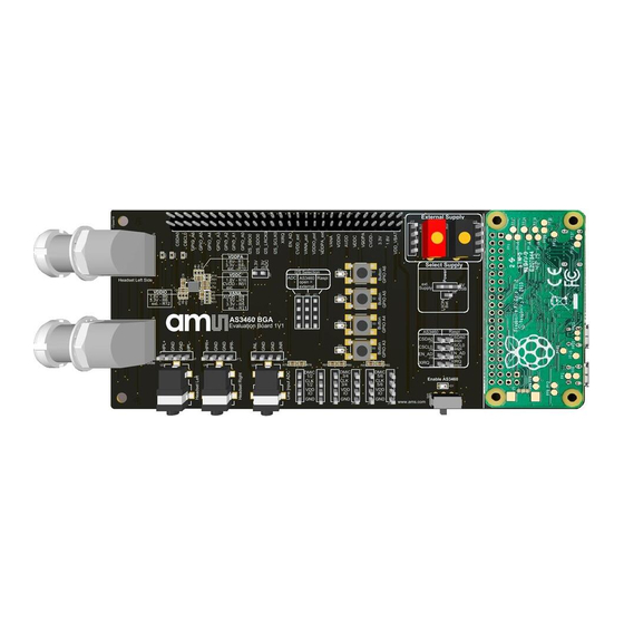
Page 12: Evaluation Board
Document Feedback AS3460 Evaluation Board Evaluation Board All block functions on the AS3460 Evaluation Board are explained in detail below. Default Jumper Setting The Evaluation Board has default jumper settings, which are marked in the color “Orange” below. Figure 12:... -
Page 13: Power Supply
Document Feedback AS3460 Evaluation Board Power Supply There are three different options to supply the hardware. Figure 14: Different Supply Options The schematic drawing describes the different supply options, which can be chosen by setting the jumper J28 accordingly. Figure 15: Schematic - Different Supply Options Demo Kit Manual •... - Page 14 Document Feedback AS3460 Evaluation Board ● Option 1: 5 V USB Plug 5 V USB cable from the PC to the “Power 5 V- USB Connector” on the Raspberry Pi Board. Ensure that the USB port of the PC is USB 3.0. This setting will be the standard configuration setting on the board.
- Page 15 Document Feedback AS3460 Evaluation Board ● Option 2: External Supply (headers and connectors) The Evaluation Board can be powered via an external power supply (3.3 V – 5 V) or with a Li-Ion- Battery, which can be connected to the “External Supply” headers or connectors.
- Page 16 Document Feedback AS3460 Evaluation Board Figure 20: Select Supply – Power Pin to “ext. Supply” ● Option 3: Li-Ion Battery The Evaluation Board can be powered via a Li-Ion-Battery, which can be soldered on the bottom side of the PCB. There are two solder pins, called “LI-ION-Battery Connection – Bat+1 / Bat-1” available.
- Page 17 At the PMU (Power Management Unit) section, there is a charger assembled, which provides the proper supply for the battery. Figure 24: Charger – Schematic In addition there are DCDCs (3V3, 1V8) assembled, which provide the power supply for the AS3460 Demo Kit Manual • PUBLIC UG000480 • v3-00 • 2021-Nov-08 │ 17...
- Page 18 Document Feedback AS3460 Evaluation Board Figure 25: Measurement Pins – Power Pin and DCDCs There are also measurement pins of the DCDC (below the Raspberry Pi PCB) Power Pin 3.3 V DCDC to 3.3V and Power Pin 1.8 V DCDC to 1.8 V.
-
Page 19: Power On/Off
Evaluation Board Power ON/OFF The device start-up and power-down is controlled with the EN pin of AS3460. A rising edge on the EN input pin will trigger start-up of the device. Once EN pin is high the integrated regulators are powering up to generate analog audio- and digital core supply voltage. - Page 20 AS3460 Evaluation Board In general, the LEMO connectors are not assembled on the evaluation board, but the footprints are available on the board. These LEMO connectors are used for all ams reference designs (reference earbud demonstrators). Figure 28: Headphone Connectors The LEMO connectors can be soldered on the evaluation board.
-
Page 21: Line Input Connectors
Line Input Connectors The AS3460 does support one stereo I S input and two stereo output channels. In addition, the AS3460 Evaluation Board has a Line Input ADC Connector (3.5 mm audio jack connectors and headers) for music playback. Figure 30:... -
Page 22: Digital Microphone Connectors
EMI interference in an application. The integrated oscillator and PLL do provide the system clock for AS3460, which is also used for the digital microphone interface. It is possible to operate the microphone interfaces with different clock rates, which may help to reduce power consumption in case the full bandwidth of the microphones is not required. - Page 23 The schematic shows the pinout of the digital microphone headers. Figure 35: Digital Microphone Headers - Pinout On the bottom side of the AS3460 Evaluation Board are microphone clock buffers assembled, which support headset with longer cables with a proper clock signal. Demo Kit Manual • PUBLIC UG000480 •...
- Page 24 Document Feedback AS3460 Evaluation Board Figure 36: Clock Buffers The schematic below shows the used buffers and the pin configuration of these parts. Figure 37: Schematic - Clock Buffers Demo Kit Manual • PUBLIC UG000480 • v3-00 • 2021-Nov-08 │ 24...
-
Page 25: Raspberry Pi Board
The default I C address for AS3460 is 0x45. This can be changed to 0x44 by pulling GPIO A0 high and power cycling the device. This is illustrated in Figure 103 for the lower board. It is necessary to restart Flex whenever the I C address of AS3460 is changed. -
Page 26: I 2 S Selection
Asynchronous Sample Rate Converter (ASRC1) to synchronize it to the internal clock domain of AS3460. The output of ASRC is fed into the AHE for additional signal processing and audio playback. The stereo audio output (SDO0) at I2S#0 interface allows to send for example raw microphone data back to the host. -
Page 27: Gpio Buttons
3.10 GPIO Buttons AS3460 supports a general-purpose I/O interface, which allows to be configured as button interface for standalone mode operation to switch between ANC and augmented operation modes or mute audio outputs. When configured as inputs each pin can have internal pull-up/down resistor enabled to avoid floating inputs. -
Page 28: Measurement Header
3.11 Measurement Header This header provides every pin of the AS3460 IC, the power and DCDC supplies. The second pin row is ground. The measurement pins can also be used to connect for instance a BT SoC to the evaluation board to test the hardware. - Page 29 Document Feedback AS3460 Evaluation Board Figure 45: Measurement Header Pinout of the measurement header J300 is shown below. Figure 46: Measurement Header – Pinout Demo Kit Manual • PUBLIC UG000480 • v3-00 • 2021-Nov-08 │ 29...
-
Page 30: As3460 Ic
AS3460 Evaluation Board 3.12 AS3460 IC The AS3460 is a digital augmented hearing companion device. The figure below shows the AS3460 IC and the external components on the Evaluation Board. Figure 47: AS3460 IC with External Components on Evaluation Board The zoom in picture displays the AS3460 IC with the passive components (capacitors and resistors) around in detail. - Page 31 VDDIO: 1.8 V – R6 Figure 49: Schematic – Different Configurations of the Supply Pins of AS3460 Every supply pin can be connect to +1.8 V, +3.3 V or to an external supply. Therefore, the correct resistor has to be assembled on the board. The external supply has to be connected to the correct pin on the measurement header J300.
-
Page 32: Pcb Design
PCB Design The figure represents the necessary amount of external components. Figure 50: AS3460 IC with the Necessary Amount of External Components This table reflects the PCB size of a single sided PCB. Figure 51: Table - PCB Area Calculation/Single Sided PCB... -
Page 33: Pcb Layout Recommendation
Figure 52) is given below: Figure 52: PCB Area Calculation / Single Sided PCB It is recommended to use a four Layer PCB to route all pins of the AS3460 IC. 4.1.1 Component Placement Recommendation This chapter provides detailed information about recommended external components. - Page 34 The VANA supply pin with an input supply range of 1.7 V up to 3.6 V is used to source the analog audio LDO, which provides the necessary supply voltage for the DAC and headphone amplifier. The integrated regulator allows AS3460 to be supplied directly with a DCDC converter maintaining highest μ...
- Page 35 A weak signal line on any of these connections can influence channel separation of the device. The ground pins of the AS3460 IC and the external components are directly connected through Vias to a dedicated ground (GND) plane below this area. The ground plane should be connected to the battery terminal for best grounding effect.
- Page 36 Document Feedback AS3460 PCB Design Figure 56: PCB Layout Bottom Layer – Components On Single Side, Not All Pins Are Routed If user has to route all pins out, there is an example shown below. As already mentioned above, it is important to put the coupling capacitors as close as possible to the supply pins.
- Page 37 Document Feedback AS3460 PCB Design Figure 58: PCB Layout Signal Layer 1– All Pins Routed Figure 59: PCB Layout Signal Layer 2 – All Pins Routed Demo Kit Manual • PUBLIC UG000480 • v3-00 • 2021-Nov-08 │ 37...
- Page 38 Document Feedback AS3460 PCB Design Figure 60: PCB Layout GND Layer – All Pins Routed Demo Kit Manual • PUBLIC UG000480 • v3-00 • 2021-Nov-08 │ 38...
- Page 39 Document Feedback AS3460 PCB Design 4.1.2 Package Outline Drawing Figure 61: AS3460 Package Drawing (FBGA36) A1 BALL CORNER 0.10 C 0.10 C B (2X) (0.45) 0.260±0.04 3.00 3.00 0.18±0.05 SEATING PLANE 0.08 C 0.9±0.1 TOP VIEW SIDE VIEW A1 BALL CORNER 36X 0.250±0.05...
-
Page 40: Flex Filter Description
Document Feedback AS3460 FleX Filter Description FleX Filter Description In this section the different filters which are available in Flex are described. Please find also a description of how to import biquad filter coefficients into Flex. Filter Tabs Next to the leftmost column the tuning tab is structured in subtabs, one for each filter. All subtabs have an identical structure, with one column for each filter. - Page 41 Document Feedback AS3460 FleX Filter Description High Pass Figure 63: High Pass ● -3dB at cutoff frequency ● -6dB per Octave below cutoff frequency ● From 90° to 45° at cutoff frequency to 0°. Demo Kit Manual • PUBLIC UG000480 • v3-00 • 2021-Nov-08...
- Page 42 Document Feedback AS3460 FleX Filter Description Automatic Gain Control (AGC) Figure 64: Automatic Gain Control ● Limiter with adjustable threshold, attack and release time. Demo Kit Manual • PUBLIC UG000480 • v3-00 • 2021-Nov-08 │ 42...
- Page 43 Document Feedback AS3460 FleX Filter Description Downsampler Lowpass Figure 65: Downsampler Lowpass ● Four filter types: LowpassX1, LowpassX2, Chebyshey Butterworth. ● Available settings and frequency response depend on filter type. ● Below example of Chebyshev from left column. Demo Kit Manual • PUBLIC UG000480 •...
- Page 44 Document Feedback AS3460 FleX Filter Description Gain Figure 66: Gain ● Gain of up to 24 dB. ● Inverting provides a phase shift of 180° without affecting the amplitude. Demo Kit Manual • PUBLIC UG000480 • v3-00 • 2021-Nov-08 │ 44...
- Page 45 Document Feedback AS3460 FleX Filter Description Shelf Figure 67: Shelf ● 6 dB per Octave until specified gain was reached Demo Kit Manual • PUBLIC UG000480 • v3-00 • 2021-Nov-08 │ 45...
- Page 46 Document Feedback AS3460 FleX Filter Description Peak or Notch Figure 68: Peak or Notch ● Specified gain at center frequency. ● Adjustable Q-Factor or bandwidth. ● 0° phase shift at center frequency ● ● Demo Kit Manual • PUBLIC UG000480 • v3-00 • 2021-Nov-08...
- Page 47 Document Feedback AS3460 FleX Filter Description Low Pass Figure 69: Low Pass ● -6 db per octave above cutoff frequency. ● 0° to -45° phase shift at cutoff frequency to -90° above. Demo Kit Manual • PUBLIC UG000480 • v3-00 • 2021-Nov-08...
- Page 48 Document Feedback AS3460 FleX Filter Description Allpass Figure 70: Allpass ● Used for phase optimizing. Demo Kit Manual • PUBLIC UG000480 • v3-00 • 2021-Nov-08 │ 48...
- Page 49 Document Feedback AS3460 FleX Filter Description 1st Order x2 Figure 71: 1st Order x2 ● Combines 2 first order filter Demo Kit Manual • PUBLIC UG000480 • v3-00 • 2021-Nov-08 │ 49...
-
Page 50: Importing Biquad Coefficients
More details can be found at the “Importing Biquad Coefficients” section Importing Biquad Coefficients The Flex filter design tool allows customers to design filters for the AS3460 ANC device. External coefficients can be imported into FleX as biquad. The term biquad is equivalent to the term “second order section”. - Page 51 Document Feedback AS3460 FleX Filter Description Figure 73: Biquad Filter Structure The coefficients are described below: Figure 74: Coefficients Coefficient Range Description [-2.0, 2.0) The first feedforward coefficient [-2.0, 2.0) The second feedforward coefficient [-2.0, 2.0) The third feedforward coefficient A constant value always equal to 1.0...
- Page 52 Document Feedback AS3460 FleX Filter Description 5.2.1 Biquad Filter Strip To select the interface where the biquad filter coefficients can be inserted, please select “Biquad coefficients” in the filter strip menu. Then the biquad coefficients input mask appears: Figure 75: Interface for Controlling a Single Filter Block Coefficients can be inserted either manually or via importing an ASCII Text file (button “IMPORT”).
- Page 53 Document Feedback AS3460 FleX Filter Description Examples using valid import formats are shown below: [ 2.61652695e-04, 5.23305390e-04, 2.61652695e-04, 1.0 , -1.95372795e+00, 9.54774560e-01] [ 0.02162072, 0.04324144, 0.02162072, 1. , -1.54312113, 0.629604 ] # Low pass at 10kHz 0.99768867 -1.99537735 0.99768867 1. -1.99537201 0.99538269 * High pass at 100Hz (0.50057783 -0.99882295 0.49826652 1.00000000 -1.9976459 0.99768869) / Peak at...
- Page 54 Document Feedback AS3460 FleX Filter Description 5.2.3 Examples Multiple Biquad Import Example 1 Figure 76: Import Example 1 Import example where there are 4 “Biquad Coefficients” controls and 4 sets of coefficients in the imported file. The operation succeeds with no errors or warnings Demo Kit Manual •...
- Page 55 Document Feedback AS3460 FleX Filter Description Multiple Biquad Import Example 2 Figure 77: Import Example 2 Import example where there are multiple “Biquad Coefficients” controls in a row, but there are more sets of coefficients in the imported file than there are controls.
-
Page 56: Anc Tuning Guide
Document Feedback AS3460 ANC Tuning Guide ANC Tuning Guide The following section will demonstrate how to tune a feedback system. Feedback 6.1.1 Theory In a feedback ANC system, the microphone is positioned inside the ear cup, next to the speaker. The microphone is sensing the noise coming from outside, already damped by the passive attenuation of the headphone cup. - Page 57 Document Feedback AS3460 ANC Tuning Guide This leads (without derivation) to the ideal filter transfer function: Equation 2: −1 −1 −1 ( s ) = − �� ( �� ) �� ( �� ) �� (��) �� �� �� The three transfer functions on the right hand side are often grouped together as the “Driver to Feedback Microphone”...
- Page 58 Document Feedback AS3460 ANC Tuning Guide The optimal filter is a compromise between stability and performance, where the maximum achievable performance is a property of the headphone’s acoustics. A large speaker will have a better low frequency response, allowing to bring down the phase at a lower frequency without requiring too much bass boost and less gain in the filter reduces stability problems.
- Page 59 Document Feedback AS3460 ANC Tuning Guide Demo Kit Manual • PUBLIC UG000480 • v3-00 • 2021-Nov-08 │ 59...
- Page 60 Document Feedback AS3460 ANC Tuning Guide 6.1.4 Performance Evaluation Stability Testing The next step after loading the new filter to the chip (“Write to AHE”) is to test whether this filter is stable in all use cases. An end-user should never experience howling sounds in his ear or feel that the earphone is causing a pressure sensation (this would be due to low-frequency overshoots).
-
Page 61: Feed Forward
Document Feedback AS3460 ANC Tuning Guide Feed Forward 6.2.1 Theory While feedback ANC is based on a control loop, the feed forward ANC is based on a different principle: As sound passes from the outside of the headphone through the headphone’s structure to the ear, it is subject to a frequency dependent dampening. -
Page 62: Example
Document Feedback AS3460 ANC Tuning Guide Equation 4: �� (��) �� ( �� ) = − �� �� ( �� ) ∙ �� ( �� ) ∙ �� �� (��) �� �� �� It is not necessary to measure these transfer functions separately, as they are all included in the... - Page 63 Document Feedback AS3460 ANC Tuning Guide Figure 82: Example (part 1) Demo Kit Manual • PUBLIC UG000480 • v3-00 • 2021-Nov-08 │ 63...
- Page 64 Document Feedback AS3460 ANC Tuning Guide Figure 83: Example (part 2) Demo Kit Manual • PUBLIC UG000480 • v3-00 • 2021-Nov-08 │ 64...
- Page 65 Document Feedback AS3460 ANC Tuning Guide Figure 84: Example (part 3) Demo Kit Manual • PUBLIC UG000480 • v3-00 • 2021-Nov-08 │ 65...
-
Page 66: Alc Tuning Guide
DSP programming or scripting required, because everything can be configured graphically within the ams Flex tool. The Flex tool provides a graphical interface for filter tuning, simulation, parameter setting and everything else there is to configure on AS3460. This tutorial shows the recommended design flow for configuring AS3460’s ALC algorithm for a new earphone model. -
Page 67: Measuring Alc Headphones
The first series of measurements is used to check the acoustic properties of the headphone. It requires the use of an ear simulator, which can simulate variable leakage. We recommend the ams Leakage Adapter. Perform several characterization measurements starting at the 0mm² leakage up to 28mm²... - Page 68 AS3460 ALC Tuning Guide Figure 86: Driver Response of ams Loose Fit Reference Design Visible is the 'knee' at 80Hz, which is the basstube resonance. The basstube helps to maintain a good low frequency response at high leakages. In addition, you can check the isolation of the feed forward microphone from the speaker: Figure 87: Driver Response at Feed Forward Microphone vs.
- Page 69 We have found that the currently available ear simulators do not behave like real ears for higher leakages, which is why we have developed the ams leakage adapter. If you have access to an ams leakage adapter, you can re-use the measurements of the first series and select five characterizations based on equally spaced feed forward targets.
-
Page 70: Project Setup
ALC Tuning Guide Leakage Range If you do not have an ams leakage adapter available, the filter tuning should be based on real ear measurements instead. Perform characterization measurements for three steps in between the lowest and highest leakage, measuring five leakage conditions. Ideally, these five steps are equally spaced. - Page 71 Figure 89: Flex Connection Window After connecting, you might be asked to update the Raspberry Pi backend and/or the AS3460 firmware. Confirm both, because a specific version of Flex will only be compatible with the correct backend and firmware. All versions of Flex are capable of up- or downgrading the firmware and backend as required.
- Page 72 Ear measurements (D2E, A2E…) are not required for ALC and are not available if your characterization was based on in-ear measurements. If you have used the ams Leakage Adapter and therefore have the D2E, A2E and A2E(open) measurements available, you can still import them, since they are useful for displaying the total noise attenuation and music equalization.
- Page 73 Document Feedback AS3460 ALC Tuning Guide Figure 91: Recommended Folder and File Structure Figure 92: Measurement Data Import Demo Kit Manual • PUBLIC UG000480 • v3-00 • 2021-Nov-08 │ 73...
- Page 74 The measurement equipment will add a gain to the driver response, which must be compensated. E.g. in the ams lab setup, we use an AudioPrecision device set to −20dBV output level and an 0dB gain headphone amplifier, therefore the gain offset amounts to 20 dB. Since you will probably perform all measurements with the same setup, you can use the "Apply changes to"...
- Page 75 Document Feedback AS3460 ALC Tuning Guide Figure 93: Bode Plot from Imported FRs Phase Calibration When using microphones, which have different polarity, e.g. using a Knowles SPG08P4HM4H-1 top port as feed forward microphone and a SPH0655LM4H-1 bottom port as the feedback microphone, it will be necessary to invert the microphone signal before it enters the algorithm.
-
Page 76: Signal Routing And System Configuration
Document Feedback AS3460 ALC Tuning Guide Signal Routing and System Configuration Before starting the filter design, some settings must be made in the routing tab. Make sure to select the correct sample rate and microphone clock rate for your project as these parameters affect the filter design. - Page 77 Document Feedback AS3460 ALC Tuning Guide The lowest leakage state should be quite similar for most people and easily reproducible, which is why the tuning procedure starts as if tuning a static ANC headphone. Mute all filters in all presets except for the low leakage feed forward filter and tune this filter to match the target.
- Page 78 Document Feedback AS3460 ALC Tuning Guide Figure 96: Target, Filter Response and Performance Simulation For the Filter in the Previous Figure Once the filter design is complete, you can write the program to AHE and evaluate the ANC performance. Before putting the earphone into your ear, please check that it is stable and that e.g.
-
Page 79: Feed Forward Tuning - High Leakage And Adaption
The commonly available ear simulators (e.g. HATS) which are, as mentioned before, not suitable for characterizing leaky headphones, are also not suitable for measuring ANC performance in leaky headphones. Please use the ams leakage adapter or measure the performance in a real ear by probing the feedback microphone. - Page 80 Document Feedback AS3460 ALC Tuning Guide On clicking "Adapt" in the simulation tab, Flex will simulate the noise cancellation performance for the in-between leakages. Use this to check if your two filters also work well when used in parallel. 7.7.1...
- Page 81 Document Feedback AS3460 ALC Tuning Guide State Id State Description The algorithm detected that the noise cancellation performance is good, that means that the current leakage estimate is accurate. In this state, the "Good" algorithm will ramp up the feedback filter gains and slow down the feed forward adaption in order to converge more precisely.
-
Page 82: Feedback Filter
Document Feedback AS3460 ALC Tuning Guide Does Not Reach gm_state_left = 0 ● If the algorithm does not reliably reach the gm_state_left = 0 state in all leakage conditions, either the ANC performance achieved with the current filters is not good enough or a corner case prevents the state transition. - Page 83 Document Feedback AS3460 ALC Tuning Guide Figure 98: Feedback Filter Examples Always run the auto adaption ("Adapt" button in the simulation tab) before testing a new or modified set of low and high leakage feedback filters. The auto adaption routine calculates several important parameters from the measurement data and filters.
-
Page 84: Music Compensation
Document Feedback AS3460 ALC Tuning Guide increased stability margin but there is also a sub-algorithm in place for detecting instabilities. The proper functioning of this algorithm should be tested for each earphone design. Before testing, activate the corner cases „Enable FB stabilizer“, „Enable FB Mic Blocked“ and if available on the earphone „Use external proximity sensor“. - Page 85 Your setting of this adaptive peak filter serves only for the simulation and will be overwritten by the auto adaption. On AS3460 running ALC it will be adapted in real-time. Once both filter stages are tuned for both leakages, disable „MC Tuning“ and check if the combined filter also matches the combined target and provides a good cancellation performance.
- Page 86 Turn down the music gain by at least 20 dB to avoid speaker and, if you intend to perform the measurement in your ear instead of the ams leakage adapter, to avoid hearing damage The music response checker will require a WAVE file containing white noise named "White.wav" to be uploaded to the Raspberry Pi.
-
Page 87: Algorithm Parameters
Document Feedback AS3460 ALC Tuning Guide Figure 101: Result of the Music Response Checker for a Music Compensation Tuning that Needs Some More Work Run the "Check Leakage" process to configure the next measurement routine for this particular leakage condition. This process will also check that the noise level is in the correct region and indicate whether further adjustments to the music level are needed. - Page 88 Document Feedback AS3460 ALC Tuning Guide 7.10.1 Algorithm Management The algorithm calculates an estimate of the noise cancellation effectiveness. If the noise cancellation is effective, the algorithm knows that its current leakage estimate is close to the real leakage and it is therefore safe to activate feedback ANC.
- Page 89 Document Feedback AS3460 ALC Tuning Guide above the second, it might switch to the different method. Lower the second threshold if you observe that the feed forward gains become unstable on music playback. If you observe that the leakage estimation changes in a stable way when increasing the music level without changing the leakage, you should tune the leakage estimation effectiveness Threshold.
-
Page 90: Elf Stage
Document Feedback AS3460 ALC Tuning Guide ● FB Mic Blocked ● Adaption Guard They are independent of the earphone's acoustic properties and filter tuning and therefore do not require any tuning. Explanations on what these corner case algorithms do is provided by the tooltips. -
Page 91: Dual Chip Operation
Document Feedback AS3460 Dual Chip Operation Dual Chip Operation How to Operate in Dual Mode? 8.1.1 Basic Setup Connect the 2 boards as shown in Figure 103. The board with the GPIO A0 pulled high will change to address 0x44 after power cycle the chip. - Page 92 Document Feedback AS3460 Dual Chip Operation 8.1.2 Using Flex with dual mode. Figure 103: Dual Board Configuration Default chip address 0x45 Connected to host Connect CSDA, Pull GPIO A0 high to set chip address to 0x44 CSCL and GND Remove I2C jumpers!
- Page 93 Document Feedback AS3460 Dual Chip Operation Figure 104: Dual Chip Address Both chips must be set to AHE “Mono” mode. (When Dual mode is selected it is also shown in the AHE Mode selector) Figure 105: Dual Mono Mode in Flex Depending on the selected channel (left or right) the corresponding filter settings will be written to the pre-defined chip (e.g.
- Page 94 Document Feedback AS3460 Dual Chip Operation Figure 106: Left / Right Selection Note: Only the filter parameters are synchronized with the L/R selector when writing to AHE. The routing and all other chip settings are written to the currently selected chip. The status of the valid connection can be seen in the connected symbol/tab.
-
Page 95: I2S Swap Function
2 AS3460 in mono mode are connected to e.g. 1 stereo Bluetooth device. Because the AS3460 in mono mode is always using the Left channel it is necessary to route the right Music input signal to the left channel. - Page 96 Document Feedback AS3460 I2S Swap Function If 2 chips are connected the swap function will be stored to each chip separately. TDM will swap channels 0 and 1. Demo Kit Manual • PUBLIC UG000480 • v3-00 • 2021-Nov-08 │ 96...
-
Page 97: Automatic Preset Selection (Aps)
Document Feedback AS3460 Automatic Preset Selection (APS) Automatic Preset Selection (APS) 10.1 How Does Automatic Preset Selection (APS) Work? 10.1.1 Basic Functionality of the APS Algorithm For details, please refer to Figure 110 below. Demo Kit Manual • PUBLIC UG000480 • v3-00 • 2021-Nov-08... - Page 98 Document Feedback AS3460 Automatic Preset Selection (APS) Figure 110: APS Algorithm Demo Kit Manual • PUBLIC UG000480 • v3-00 • 2021-Nov-08 │ 98...
- Page 99 Document Feedback AS3460 Automatic Preset Selection (APS) The APS Algorithm selects the best ANC-Filter for a given noisy environment based on an analysis of the Feedforward microphone signal. That means that it analyses the frequency bands of the noise signal and selects the preset with the filter that is mostly cancelling the noise in the frequency band where the most energy of the noise signal is located.
- Page 100 Document Feedback AS3460 Automatic Preset Selection (APS) Example: In the following example the 1000 Hz band would be the most dominant, but since the weighting factor was scaled to -40 dB the 300 Hz band becomes the most dominant. The threshold factor is set to 1 dB, therefore if the level of the 300 Hz band drops by 1 dB the next band will be the most dominant, here this Is the 30 Hz band.
-
Page 101: Using Aps In Flex
Document Feedback AS3460 Automatic Preset Selection (APS) 10.1.5 APS and ALC APS is a functionality in the ANC-Hybrid Topology, therefore it is not possible to use ALC at the same time, since this needs the ALC-Hybrid Topology. 10.2 Using APS in Flex APS can be activated and controlled via the “APS”-Tab in the “Configuration”-Tab. - Page 102 Document Feedback AS3460 Automatic Preset Selection (APS) Control Range Unit Description Name APS Presets The number of presets assigned to APS. Selected Presets will be used for APS. Other presets are APS Presets presumed to be assigned for other purposes (for example...
-
Page 103: Simple Aps Example
Document Feedback AS3460 Automatic Preset Selection (APS) 10.3 Simple APS Example 10.3.1 Open APS Project The first step is to open a new project with a Hybrid ANC Topology. Figure 116: Opening APS Example Project 10.3.2 Load Frequency Response with All Zeros For this step, you need the Excel-File with zeros at all frequency steps and at all phase steps (ALL_zero.xls) you received with this description or you can request at the PS Audio Apps Team. - Page 104 Document Feedback AS3460 Automatic Preset Selection (APS) In the end, it should look like this: Figure 117: APS Example Project Tab 10.3.3 Routing In the routing tab, please route DMIC1L to FF Left and DMIC1R to FF Right as you see it in the following picture.
- Page 105 Document Feedback AS3460 Automatic Preset Selection (APS) Figure 118: APS Example Routing Tab 10.3.4 Tuning In the Tuning Tab we now prepare the 4 presets so that we can use it afterwards for the Automatic Preset Selection (APS). Preset 1 In Preset 1, apply a Peak Filter with a Q of 2.00 to a frequency of 30 Hz with the gain of 1 dB.
- Page 106 Document Feedback AS3460 Automatic Preset Selection (APS) Figure 119: APS Example Preset 1 Demo Kit Manual • PUBLIC UG000480 • v3-00 • 2021-Nov-08 │ 106...
- Page 107 Document Feedback AS3460 Automatic Preset Selection (APS) Preset 2 In Preset 2, apply a Peak Filter with a Q of 2.00 to a frequency of 100 Hz with the gain of 1 dB. This creates a noise cancellation at 100 Hz with about -45 dB.
- Page 108 Document Feedback AS3460 Automatic Preset Selection (APS) Preset 3 In Preset 3, apply a Peak Filter with a Q of 2.00 to a frequency of 300 Hz with the gain of 1 dB. This creates a noise cancellation at 300 Hz with about -45 dB.
- Page 109 Document Feedback AS3460 Automatic Preset Selection (APS) Preset 4 In Preset 4, apply a Peak Filter with a Q of 2.00 to a frequency of 1400 Hz with the gain of 3 dB. This creates a noise cancellation at 1000 Hz with about -45 dB.
- Page 110 Document Feedback AS3460 Automatic Preset Selection (APS) 10.3.5 Starting the APS Algorithm The last step is to activate the APS Algorithm with the Standard settings as shown in the following figure. This can be done in the “Configuration” Tab at “APS”. Just activate the switch “APS enabled”. If you are not sure that you have the default values, just press the “Default”...
-
Page 111: Anc Characterization
A good and tight fit of the headphone on the artificial head has to be ensure 11.1.1 Measurement The measurement can be performed with the Audio-Precison Templates “Hybrid_Characterization.approjx” or “Hybrid_Characterization_FB_FF_seperate.approjx”, which will be provided by ams. The measurement setup looks as follows: Figure 124: ANC Characterization Measurement Setup Demo Kit Manual • PUBLIC UG000480 •... - Page 112 Document Feedback AS3460 ANC Characterization The Audio-Precision Templates provide the following output files: ● ● D2FB ● D2FF ● ● A2FB ● A2FF ● A2E (Open) remove headphone/ earbud from measurement equipment These output files can directly be loaded into the Flex Project.
-
Page 113: Alc Characterization
The ALC algorithm running on AS3460 will adapt the ANC filters in real time to compensate for this leakage to give constant ANC performance for all acoustic leakage conditions. - Page 114 “AP_ALC_Template_UCU.approx” AP template provided by ams should be used here. The template will generate the following output files: D2E, D2FB, D2FF, A2E, A2FB, A2FF, A2E(open). The characterization process should be repeated for the following 5 different leakages.
- Page 115 Document Feedback AS3460 ALC Characterization Figure 127: D2E Measurement for Different Acoustic Leakages The figure above shows the D2E response for different leakages. It can be seen that the bass response decreases with increasing leakage. The range in between the lowest and highest leakage is the leakage range that the ALC can compensate.
- Page 116 D2FF used in Flex “D2FF” A2FB used in Flex “A2FB” and “A2E” A2FF used in Flex “A2FF” and “A2E (Open)” “AP_ALC_Template_Human_Ear.approx” AP template provided by ams should be used here. Demo Kit Manual • PUBLIC UG000480 • v3-00 • 2021-Nov-08 │ 116...
- Page 117 Document Feedback AS3460 ALC Characterization Figure 130: Human Head Measurement Setup Demo Kit Manual • PUBLIC UG000480 • v3-00 • 2021-Nov-08 │ 117...
-
Page 118: Codec Mode
Document Feedback AS3460 Codec Mode Codec Mode Codec Mode is a power saving music only mode (ANC Off). Figure 131: Codec Mode Enabling The music filters for Codec mode must be applied in the ALTMUSIC tab. Figure 132: Altmusic Tab Demo Kit Manual •... - Page 119 Figure 133: I2S0 Settings As long as AS3460 is in Codec operation mode a host MCU is not supposed to write to any other register than the AUDIO_CONTROL register. Please refer to the data sheet for more details. Demo Kit Manual • PUBLIC UG000480 •...
-
Page 120: Deep Sleep Mode
To enable the deep sleep mode, sequentially write 0xa and 0x7 to the following register: Figure 134: Deep Sleep Mode Register Please refer to the AS3460 data sheet for more details. Demo Kit Manual • PUBLIC UG000480 • v3-00 • 2021-Nov-08... -
Page 121: Wind Noise Detection
Document Feedback AS3460 Wind Noise Detection Wind Noise Detection Figure 135: Wind Noise Detection Parameters in FleX 15.1 Overview This section describes the functionality of the wind noise suppression and the process to set its parameters for which will likely require tuning for each new demonstrator / headphone model. -
Page 122: Operation
Document Feedback AS3460 Wind Noise Detection 15.2 Operation Wind can create very loud sound pressure at the outer microphone positions of the headphone (FF & Speech microphone). This can lead to digital signal clipping inside the AHE engine and audible distortions. -
Page 123: General Tuning Process
Document Feedback AS3460 Wind Noise Detection In the ALC example shown in the figure above it can be seen how the FF gains ramp down once the wind metric exceeds the low wind threshold. It can also be seen that the FB gains are not affected. -
Page 124: Parameters
Document Feedback AS3460 Wind Noise Detection “Wind Detection Attack Time” This governs the attack time of the wind noise metric. It is recommended to keep it low for quick responses. This does not control the gain adjustment rate, just the metric ramp up time of WIND_NOISE_METRIC in the presence of possible wind. -
Page 125: Revision Information
Document Feedback AS3460 Revision Information Revision Information Changes from previous version to current revision v3-00 Page Adapted APS chapter 101 - 114 Added Dual Mode chapter 95 - 98 Added I2S Swap chapter 99 - 100 Added Deep Sleep Mode section... -
Page 126: Legal Information
AG shall not be liable to recipient or any third party for any damages, including but not limited to personal injury, property damage, loss of profits, loss of use, interruption of business or indirect, special, incidental or consequential damages, of any kind, in connection with or arising out of the furnishing, performance or use of the technical data herein.
Need help?
Do you have a question about the AS3460 and is the answer not in the manual?
Questions and answers