
Subscribe to Our Youtube Channel
Related Manuals for AMS AS703X_EVALKIT_BT


Summary of Contents for AMS AS703X_EVALKIT_BT
- Page 1 User Guide UG001014 AS7030B/AS7038GB/ AS7038RB Evaluation Kit User Guide v1-00 • 2021-May-06...
-
Page 2: Table Of Contents
Document Feedback AS7030B/AS7038GB/AS7038RB Content Guide Content Guide ADC and FIFO ..........17 Introduction ........3 Digital Interface ........... 19 Kit Content ............ 3 Sampling Sequencer ........19 Ordering Information ........4 Software Description ....25 Getting Started ......5 Software Architecture ......... 25 Hardware Description .... -
Page 3: Introduction
Document Feedback AS7030B/AS7038GB/AS7038RB Introduction Introduction The AS7030B/AS7038GB/AS7038RB Evaluation Kit allows evaluation of all functions on the AS7030B/AS7038GB/AS7038RB Biosensor and test them in various applications. The initial Evaluation Kit works with USB connection to the PC and comes with a GUI, which enables the user to change AS7030B/AS7038GB/AS7038RB register settings, see measurement results and many more. -
Page 4: Ordering Information
Blade connector J502 on the Mainboard. As a result, the sensor part of the kit needs to be separated from the Mainboard. Any signals important for development are accessible for probing at pin headers. Ordering Information Ordering Code Description AS703X_EVALKIT_BT Evaluation Kit for AS7030B/AS7038GB/AS7038RB AS7030B_WRISTBAND Wristband to connect to AS703x EvalKit AS7038GB_WRISTBAND Wristband to connect to AS703x EvalKit... -
Page 5: Getting Started
AS7030B/AS7038GB/AS7038RB Getting Started Getting Started The client software latest version is available for download at https://ams.com/as7030B#tab/tools https://ams.com/as7038GB#tab/tools https://ams.com/as7038RB#tab/tools or the software is possible to find on the USB stick as a part of the evaluation kit. To install, just double as shown in... -
Page 6: Hardware Description
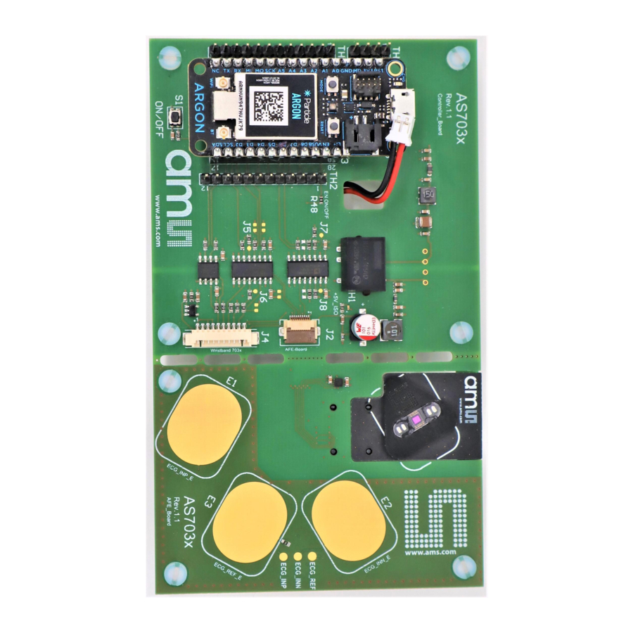
Document Feedback AS7030B/AS7038GB/AS7038RB Hardware Description Hardware Description Hardware Architecture Figure 3: AS703x Controller Board – Top View Wireless Module IEC 60601 Compilant DC-DC SMOD Interface converter ECG INN Electrode Test Point for External ECG REF Electrode Test Point for External ECG INN Electrode Test Point for External ECG INP Electrode Break Out Line Isolators for all... - Page 7 Document Feedback AS7030B/AS7038GB/AS7038RB Hardware Description Figure 4: AS703x Controller Board – Bottom View Current Measurement ADC ADS114 Connector for External Electrodes Connector for SMOD module Break out Board Connector Figure 5: SMOD703xx – Top View Internal External LEDs External External GREEN LEDs RED LEDs IR LEDs...
-
Page 8: Power Supply
Document Feedback AS7030B/AS7038GB/AS7038RB Hardware Description Figure 6: Fitting the SMOD703xx Sensor Board with the AS703x Controller Board Board is Ready ● The controller board supports AS7030B, AS7038GB & AS7038RB SMOD boards. ● The SMOD board should be mounted very carefully as shown in the Figure 6. ●... -
Page 9: As7030B/As7038Gb/As7038Rb Overview
Document Feedback AS7030B/AS7038GB/AS7038RB AS7030B/AS7038GB/AS7038RB Overview AS7030B/AS7038GB/AS7038RB Overview Based on the optical filter and photodiode size, there are three types of AS703xxB sensors. AS7030B & AS7038GB are most sensitive to green/IR light, and AS7038RB is most sensitive to red/IR light. On the other hand, AS7030B has internal LEDs (two greens and one IR LED), but AS7038GB/RB supports only external LEDs. - Page 10 Document Feedback AS7030B/AS7038GB/AS7038RB AS7030B/AS7038GB/AS7038RB Overview Figure 7: Optical Front End AS7030B AS7038GB/RB For AS7030B The optical front end consists of: ● 4 LED drivers, individually configurable, operated manually or controlled by the built-in sampling sequencer ● 2 built-in green LEDs (VD1 and VD2) ●...
- Page 11 Document Feedback AS7030B/AS7038GB/AS7038RB AS7030B/AS7038GB/AS7038RB Overview Figure 8: Photodiode Arrangement for AS7030B For AS7038GB / AS7038RB The optical front end consists of: ● 4 LED drivers, individually configurable, operated manually or controlled by the built-in sequencer ● 6 photodiodes ● 4 with green filters (PD1, PD2, PD3, and PD4) (If AS7038GB) 4 with RED/IR filters (PD1, PD2, PD3, and PD4) (If AS7038RB) ●...
- Page 12 Document Feedback AS7030B/AS7038GB/AS7038RB AS7030B/AS7038GB/AS7038RB Overview Figure 9: Photodiode Arrangement for AS7038GB and AS7038RB AS7038GB AS7038RB Eval Kit Manual • PUBLIC UG001014 • v1-00 • 2021-May-06 │ 12...
- Page 13 Document Feedback AS7030B/AS7038GB/AS7038RB AS7030B/AS7038GB/AS7038RB Overview Trans-Impedance Amplifier (TIA) ● Configurable photodiode connection ● Photodiode input current offset compensation ● Configurable gain ● 2 different modes of operation – photocurrent to voltage converter or photocurrent integrator ● Clip detection Figure 10: Trans-Impedance Amplifier ●...
-
Page 14: Ecg Amplifier
Document Feedback AS7030B/AS7038GB/AS7038RB AS7030B/AS7038GB/AS7038RB Overview Figure 11: Optical Signal Conditioning Each of the blocks depicted on Figure 11 can be individually enabled or disabled/bypassed. ECG Amplifier The ECG (electro cardiogram) amplifier is a high impedance, low noise instrumentation amplifier with analog circuitry to band pass filter the signal. - Page 15 Document Feedback AS7030B/AS7038GB/AS7038RB AS7030B/AS7038GB/AS7038RB Overview Figure 12: ECG Amplifier Circuit ecg_low_leakage_en for diode leakage reduction on ECG_INP and ECG_INN AS7030_ECG_INP Leads off detect AS7030_ECG_INN ecg_ref_en AS7030_ECG_REF SIGREF to electrical frontend Figure 13: Recommended ECG Frontend Filter ECG_INP ECG_INN ECG_REF Eval Kit Manual • PUBLIC UG001014 •...
-
Page 16: Electrical Analog Front End (Eafe)
Document Feedback AS7030B/AS7038GB/AS7038RB AS7030B/AS7038GB/AS7038RB Overview Electrical Analog Front End (EAFE) The four general-purpose pins and ECG_REF can be used as analog input pins for the electrical analog front end. The analog inputs configuration sets up different non-inverting amplifier topologies: ● With offset and input voltage divider ●... -
Page 17: Light-To-Frequency Converter (Ltf)
Document Feedback AS7030B/AS7038GB/AS7038RB AS7030B/AS7038GB/AS7038RB Overview Light-to-Frequency Converter (LTF) The LTF module can use any of the photodiodes. Photodiodes connected to the LTF cannot be used at the same time with TIA. Integration time (itime) is configured in unit steps, one unit step is 3.702 ms. The unit step can be reduced by 2, 4 or 8, this also reduces the resolution of the conversion. - Page 18 Document Feedback AS7030B/AS7038GB/AS7038RB AS7030B/AS7038GB/AS7038RB Overview When triggered from the sequencer, the channel selection is always set to the smallest channel when the sequencer starts for the first time. When sequencer starts, then stops and starts again, channel selection will not reset, it will stay at the channel it was on when the sequencer stopped. When triggered manually, the channel selection resets with every write to one of the channel selection registers.
-
Page 19: Digital Interface
Document Feedback AS7030B/AS7038GB/AS7038RB AS7030B/AS7038GB/AS7038RB Overview 4.5.2 FIFO The AS7030B/AS7038GB/AS7038RB FIFO is 256 bytes long. ADC samples are 2 bytes each, which means, FIFO can hold up to 128 samples. There is a FIFO length register, which indicates how much samples are currently available in the FIFO. The FIFO can send an interrupt when the number of available samples reaches a certain configurable threshold. - Page 20 Document Feedback AS7030B/AS7038GB/AS7038RB AS7030B/AS7038GB/AS7038RB Overview Equation 1: ������_������ ∗ (������_������ + 1) ∗ 1���� SEQ_DIV holds the value of the 1 µs input clock divider. Within one sequencer cycle, the sequencer will: ● Switch on the LEDs at the specified LED start time and then switch them off at the LED stop time.
- Page 21 Document Feedback AS7030B/AS7038GB/AS7038RB AS7030B/AS7038GB/AS7038RB Overview Figure 17: Sequencer Block Diagram 4.7.1 Sampling Rate and Subsampling Throughout this document, sampling rate refers to the rate at which the sequencer produces samples of the same ADC channel. This depends on the number of enabled ADC channels and on configuration of the subsampling feature of the sequencer.
- Page 22 Document Feedback AS7030B/AS7038GB/AS7038RB AS7030B/AS7038GB/AS7038RB Overview The register SEQ_CFG and SD_SUBS configure how subsampling will be executed: ● sd_subs field in SD_SUBS register defines if subsampling is enabled; when it is 0, no subsampling is done – every sequencer cycle triggers an ADC measurement (Figure 18); setting to N>0, enables subsampling and then for N sequencer cycles the sequencer will not trigger the ADC, followed by one cycle with ADC conversion.
- Page 23 Document Feedback AS7030B/AS7038GB/AS7038RB AS7030B/AS7038GB/AS7038RB Overview Figure 18: No Subsampling (sd_subs=0) Figure 19: Subsampling of All Enabled ADC Channels (sd_subs=2 and sd_subs_always=1) Eval Kit Manual • PUBLIC UG001014 • v1-00 • 2021-May-06 │ 23...
- Page 24 Document Feedback AS7030B/AS7038GB/AS7038RB AS7030B/AS7038GB/AS7038RB Overview Figure 20: Subsampling of 1st Enabled ADC Channel Only (sd_subs=3 and sd_subs_always=0) Eval Kit Manual • PUBLIC UG001014 • v1-00 • 2021-May-06 │ 24...
-
Page 25: Software Description
Document Feedback AS7030B/AS7038GB/AS7038RB Software Description Software Description Software Architecture Figure 21: SW Modules AS703xxB Eval Kit Manual • PUBLIC UG001014 • v1-00 • 2021-May-06 │ 25... -
Page 26: Graphical User Interface
User Guide Version - 1.00 ● Valid for the following software version - AS703x_EvalSW_v1-0-1 ● Supported hardware - AS7030B_Evalboard v1.1 ● Download - Navigate to https://ams.com/as7030B#tab/tools https://ams.com/as7038GB#tab/tools https://ams.com/as7038RB#tab/tools and download the latest version. Eval Kit Manual • PUBLIC UG001014 • v1-00 • 2021-May-06... - Page 27 Document Feedback AS7030B/AS7038GB/AS7038RB Software Description 5.2.1 Overview Figure 22 shows the main window of the graphical user interface. To connect to the board the connection control elements are used (1). The measured data is displayed in the main section of the application (6).
- Page 28 Document Feedback AS7030B/AS7038GB/AS7038RB Software Description 5.2.2 Powering Up and Starting a Measurement Connect the sensor board and the mainboard via the 10-pin flat cable if you already broke the board; otherwise, you can skip this step. Connect the micro USB to USB cable to the Bluetooth module and plug it into your computer. Afterwards, press the S1 button for 3 seconds to turn on the sensor board.
- Page 29 Document Feedback AS7030B/AS7038GB/AS7038RB Software Description Select one of the built-in configuration presets Optionally check and change AS7030B/AS7038GB/AS7038RB settings. On the first startup after SW installation no settings are loaded, after that the last used settings will be used. To start a measurement with the current settings click on the Start button. The green AS7030B/AS7038GB/AS7038RB LEDs will turn on, Start button’s caption will change to “Stop”...
- Page 30 Document Feedback AS7030B/AS7038GB/AS7038RB Software Description Figure 25: Figure 24: AS7030B/AS7038GB/AS7038RB Block Diagram Highlighted Submenu Selection Blocks are Configured in the According Submenus For further information, please refer to the AS7030B/AS7038GB/AS7038RB Datasheet. LED Configuration Attention LED current, LED mode and LED state can be set in the “LEDs configuration” window. It is recommended to configure the current only when the output is not active as there is no latch implemented to keep the 10 bits consistent.
- Page 31 Document Feedback AS7030B/AS7038GB/AS7038RB Software Description Figure 26: Figure 27: LED Configuration Submenu LED Driver Block Diagram For further information, please refer to the following document: ● AS7030B/AS7038GB/AS7038RB Datasheet Photodiodes Configuration Select the photodiodes which are to be connected to TIA input. The offset current is optional, this allows cancellation of constant light sources like sunlight.
- Page 32 Document Feedback AS7030B/AS7038GB/AS7038RB Software Description Figure 28: Figure 29: Photodiode Configuration Submenu Photodiode Block Diagram For further information, please refer to the following document: ● AS7030B/AS7038GB/AS7038RB Datasheet TIA (Trans-Impedance Amplifier) Configuration The TIA has to be configured according to the information in theAS7030B/AS7038GB/AS7038RB datasheet (table in Figure 28 AS703x Block Diagram).
- Page 33 Document Feedback AS7030B/AS7038GB/AS7038RB Software Description Figure 30: Figure 31: TIA Configuration Submenu TIA Block Diagram For changing the TIA, stick to the following suggestions: Figure 32: TIA Suggestion pd_ampres pd1234 pd_ampcap pd_ampcomp pd_ampvo Gain 1…4 1 V/µA 1…4 2 V/µA 1…4 3 V/µA 1…2...
- Page 34 Document Feedback AS7030B/AS7038GB/AS7038RB Software Description pd_ampres pd1234 pd_ampcap pd_ampcomp pd_ampvo Gain Low Bandwidth Mode 1…4 7 V/µA Integrating Mode (pd_ampres=0) 1…4 1 V/pQ 1…4 1/2 V/pQ 1…4 1/3 V/pQ pd1234 … number of active photodiodes (for example, pd1=1, pd2=0, pd3=1, pd4=0 -> pd1234=2) For further information, please refer to the following document: ●...
- Page 35 Document Feedback AS7030B/AS7038GB/AS7038RB Software Description OFE (Optical Frontend) Configuration In this window, the OFE blocks can be enabled and the filter chain is configured. Figure 33: Figure 34: OFE Configuration Submenu OFE Block Diagram Check OFE1 and/or OFE2 check box to enable the corresponding OFE block. To optimize signal quality adapt the OFE Gain setting to your application.
- Page 36 Document Feedback AS7030B/AS7038GB/AS7038RB Software Description For further information, please refer to the following document: ● AS7030B/AS7038GB/AS7038RB Datasheet Sequencer Configuration Figure 35: Sequencer Configuration Submenu The “Cycle period” field of the “Sequencer configuration” window (see Figure 35) holds the value of the SEQ_PER register.
- Page 37 Document Feedback AS7030B/AS7038GB/AS7038RB Software Description subsampling will be enabled . Please refer to Sampling Rate and Subsampling for details on sampling rate. Use this window to enable/disable ADC channels. Any change in the values of the fields for sample frequency, sample period, cycle period and in the ADC channel selection will cause a new calculation of the values for the rest of the fields.
- Page 38 Document Feedback AS7030B/AS7038GB/AS7038RB Software Description ECG Amplifier Configuration The ECG (electro cardiogram) amplifier is a high impedance, low noise instrumentation amplifier with analog circuitry to band pass filter the signal. Gain is distributed between 3 gain stages. The gain in the first stage determines the tradeoff between achievable noise level and achievable input offset voltage.
- Page 39 Document Feedback AS7030B/AS7038GB/AS7038RB Software Description Figure 39: ECG Amplifier Block Diagram ecg_low_leakage_en for diode leakage G_ina=18 reduction on ECG_INP and ECG_INN (programmable 1 .. 48) Di fferential Notch Low Pa s s Anti Al iasing Ga i n Stage Hi gh Pass Filter Stage 2 Sta ge 1 Ampl i fier...
- Page 40 Document Feedback AS7030B/AS7038GB/AS7038RB Software Description Electrical Analog Frontend Configuration The electrical analog front end consists of three identical signal paths with independent settings of bias condition, gain and offset. Here the EAF_CFG, EAF_GST, EAF_BIAS, EAF_DAC and EAF_DAC_CFG registers are set. Figure 40: Figure 41: Electrical-Analog-Frontend Configuration...
- Page 41 Document Feedback AS7030B/AS7038GB/AS7038RB Software Description Light-to-Frequency Configuration Light-to-frequency feature can be used to measure light input directly. Its main purpose is proximity detection. Attention Do not use diodes that are connected to the TIA (register PD_A, PD_B, PD1...4) at the same time when itf_en is enabled on the same diode.
- Page 42 Document Feedback AS7030B/AS7038GB/AS7038RB Software Description output” check boxes - unchecked means the pin is digital input. If the pin is set as digital output, it’s state can be set via the corresponding check box in the “Output state” group box. Figure 44: Figure 45: GPIO Configuration Submenu...
- Page 43 Document Feedback AS7030B/AS7038GB/AS7038RB Software Description Figure 46: PD Offset & LED Current Control Submenu Minimum amplitude of the controlled signal in ADC counts – If the amplitude of the ADC signal drops below that value, LED current will be increased, if LED current control is enabled. Maximum amplitude of the controlled signal in ADC counts–...
- Page 44 Document Feedback AS7030B/AS7038GB/AS7038RB Software Description Minimum threshold of the controlled signal in ADC counts – If the amplitude of the ADC signal drops below that value, LED current will be increased, if LED current control is enabled. Maximum threshold of the controlled signal in ADC counts– If the amplitude of the ADC signal grows above that value, LED current will be decreased, if LED current control is enabled.
- Page 45 Document Feedback AS7030B/AS7038GB/AS7038RB Software Description For AS7038RB The “SpO2” is for configuring the SpO2 Parameters. These parameters associated with the specific settings of the AS7038R must be entered in the SpO2 configuration settings. Because of production and assembling tolerances, it is recommended that the below-mentioned factors for the photodiode and ����...
- Page 46 Document Feedback AS7030B/AS7038GB/AS7038RB Software Description Figure 49: Register Map Dialog Saving Current Configuration Settings to a File The current configuration settings can be exported to a file. To do this, click on the “File Save Configuration” menu. This will open the “Save Configuration File” dialog box on the second picture on the right.
- Page 47 Document Feedback AS7030B/AS7038GB/AS7038RB Software Description Figure 50: Figure 51: Safe and Load Configuration Menu Safe Configuration File Dialog Entries Raw Data Logging and Exporting Before starting the measurement by clicking the “Start” button, click the “Record” button to save the raw data from the AS703x.
-
Page 48: As703X Firmware Upgrade
Document Feedback AS7030B/AS7038GB/AS7038RB Software Description Figure 53: Useful Start Settings Use Case LED Current [mA] OFE Gain Finger 0.768 Light skin wrist Dark skin wrist AS703x Firmware Upgrade 5.3.1 Controller Firmware Update over USB Connect the USB cables to the Argon board. Push “mode”... - Page 49 Document Feedback AS7030B/AS7038GB/AS7038RB Software Description Check the right COM port name from the “Device Manager” Figure 55: Device Manager Open the Application Firmware folder Figure 56: Firmware Folder Modify batch script 'update_firmware.bat' to set right virtual com port ● Open the batch script 'update_firmware.bat' with the “Notepad++” ●...
- Page 50 Document Feedback AS7030B/AS7038GB/AS7038RB Software Description Figure 57: Notepad++ ● Save the file and close the Notepad++ Double click the batch script “update_firmware.bat” to update the firmware. Figure 58: Firmware Update The message "Device programmed" and the green LED switching on, means that programming was successful.
- Page 51 Document Feedback AS7030B/AS7038GB/AS7038RB Software Description Figure 59: Update Successful Eval Kit Manual • PUBLIC UG001014 • v1-00 • 2021-May-06 │ 51...
-
Page 52: Revision Information
Document Feedback AS7030B/AS7038GB/AS7038RB Revision Information Revision Information Changes from previous version to current revision v1-00 Page Initial production version ● Page and figure numbers for the previous version may differ from page and figure numbers in the current revision. ● Correction of typographical errors is not explicitly mentioned. -
Page 53: Legal Information
AG shall not be liable to recipient or any third party for any damages, including but not limited to personal injury, property damage, loss of profits, loss of use, interruption of business or indirect, special, incidental or consequential damages, of any kind, in connection with or arising out of the furnishing, performance or use of the technical data herein.
Need help?
Do you have a question about the AS703X_EVALKIT_BT and is the answer not in the manual?
Questions and answers