
Related Manuals for AMS AS3460


Summary of Contents for AMS AS3460
- Page 1 User Guide UG000480 AS3460 Digital Augmented Hearing Demo Kit AS3460_EVALUATION_BOARD v1-00 • 2020-Jun-30...
-
Page 2: Table Of Contents
Simple APS Example ......... 97 3.11 Measurement Header ........ 28 Revision Information ....106 3.12 AS3460 IC ..........30 PCB Design ........32 Legal Information ...... 107 PCB Layout Recommendation ....33 FleX Software Manual ....40 Demo Kit Manual • PUBLIC UG000480 •... -
Page 3: Introduction
Introduction Introduction The AS3460 is a digital augmented hearing companion device ideally suited for stereo headsets and headphones as well as True Wireless applications. The extremely small form factor enables unique augmented hearing experience for its end user with negligible influence on overall playtime of the headset due to ultra-low power consumption. -
Page 4: Ordering Information
Document Feedback AS3460 Introduction ● FleX Filter Design Tool This tool allows customers to design filters for the AS3460 ANC device. Figure 2: FleX Filter Design Tool Software Ordering Information Ordering Code Description AS3460_EVALUATION_BOARD AS3460 Digital Augmented Hearing Demo Kit... -
Page 5: Quick Start Guide
Flex Software the first time. This is mandatory for proper device driver installation. Hardware Setup To use FleX, it is necessary to connect the AS3460 Evaluation Board’s RaspberryPi via USB to a windows computer. When connecting the RaspberryPi for the first time, it will show up as a mass storage device, which contains the drivers that are required for FleX to function properly. -
Page 6: Project Setup
Measurements & Calibration Next is loading the XLS files obtained from the characterization (for more details see appendix A on characterization) The AudioPrecision template provided by ams produces all the necessary files, with the same naming scheme used by FleX. - Page 7 Document Feedback AS3460 Quick Start Guide Load data by navigating to the project tab and select the required files by clicking on the dots symbol on each line. Figure 5: Measurement Sets Depending on the measurement setup it will be necessary to calibrate the measurements. To do so click on the eye symbol next to the affected measurement.
-
Page 8: Simulation Window
Figure 6: Gain and Phase Offset If the headphone’s speaker is wired inverse to the AS3460 than it was wired at the time of characterization it is necessary to compensate this using the “Phase offset”. It is not necessary to calibrate for the test speaker or reference microphone, since their impact cancels out in the calculations. -
Page 9: Filter Tuning
Document Feedback AS3460 Quick Start Guide There are some basic controls for navigating the simulation window: Figure 7: Simulation Window Controls Command Action Shift + Mouse wheel Zoom with respect to frequency Ctrl + Mouse wheel Zoom with respect to Y-axis... - Page 10 Document Feedback AS3460 Quick Start Guide Figure 9: Peak/Notch ● Adjustable frequency ● Gain ● And Q Figure 10: Shelf ● Adjustable frequency ● Separate gains for frequencies higher and lower than the center frequency ● Gain transition with 6dB/Oct.
- Page 11 A fixed number of instances of these filters can be used to build a filter. They can be controlled from the tuning tab. After completing a filter tuning, the filter can be activated on the AS3460 by clicking “Write to AHE”. Demo Kit Manual • PUBLIC UG000480 •...
-
Page 12: Evaluation Board
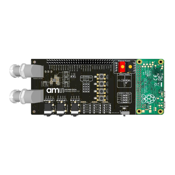
Document Feedback AS3460 Evaluation Board Evaluation Board All block functions on the AS3460 Evaluation Board are explained in detail below. Default Jumper Setting The Evaluation Board has default jumper settings, which are marked in the color “Orange” below. Figure 11:... -
Page 13: Power Supply
Document Feedback AS3460 Evaluation Board Power Supply There are three different options to supply the hardware. Figure 13: Different Supply Options The schematic drawing describes the different supply options, which can be chosen by setting the jumper J28 accordingly. Figure 14: Schematic - Different Supply Options Demo Kit Manual •... - Page 14 Document Feedback AS3460 Evaluation Board ● Option 1: 5 V USB Plug 5 V USB cable from the PC to the “Power 5 V- USB Connector” on the Raspberry Pi Board. Ensure that the USB port of the PC is USB 3.0. This setting will be the standard configuration setting on the board.
- Page 15 Document Feedback AS3460 Evaluation Board ● Option 2: External Supply (headers and connectors) The Evaluation Board can be powered via an external power supply (3.3 V – 5 V) or with a Li-Ion- Battery, which can be connected to the “External Supply” headers or connectors.
- Page 16 Document Feedback AS3460 Evaluation Board Figure 19: Select Supply – Power Pin to “ext. Supply” ● Option 3: Li-Ion Battery The Evaluation Board can be powered via a Li-Ion-Battery, which can be soldered on the bottom side of the PCB. There are two solder pins, called “LI-ION-Battery Connection – Bat+1 / Bat-1” available.
- Page 17 At the PMU (Power Management Unit) section, there is a charger assembled, which provides the proper supply for the battery. Figure 23: Charger – Schematic In addition there are DCDCs (3V3, 1V8) assembled, which provide the power supply for the AS3460 Demo Kit Manual • PUBLIC UG000480 • v1-00 • 2020-Jun-30 │ 17...
-
Page 18: Power On/Off
DCDC Schematic Power ON/OFF The device start-up and power-down is controlled with the EN pin of AS3460. A rising edge on the EN input pin will trigger start-up of the device. Once EN pin is high the integrated regulators are powering Demo Kit Manual •... -
Page 19: Headphone Connectors
The EN pin of AS3460 is typically controlled with a GPIO of the host device. Power down of AS3460 is triggered by pulling EN pin low for minimum time. Once this minimum time is reached, the power down sequence is initiated and no more I C commands from the host device are accepted. - Page 20 Document Feedback AS3460 Evaluation Board Figure 27: Headphone Connectors The LEMO connectors can be soldered on the evaluation board. For soldering, it is mandatory to follow the pinout according to the evaluation board schematic below. Figure 28: LEMO Connector Pinout Connectors can be found on the LEMO homepage: www.lemo.com/pdf/EPG.1B.310.HLN.pdf...
-
Page 21: Line Input Connectors
Line Input Connectors The AS3460 does support one stereo I S input and two stereo output channels. In addition, the AS3460 Evaluation Board has a Line Input ADC Connector (3.5 mm audio jack connectors and headers) for music playback. Figure 29:... -
Page 22: Digital Microphone Connectors
EMI interference in an application. The integrated oscillator and PLL do provide the system clock for AS3460, which is also used for the digital microphone interface. It is possible to operate the microphone interfaces with different clock rates, which may help to reduce power consumption in case the full bandwidth of the microphones is not required. - Page 23 The schematic shows the pinout of the digital microphone headers. Figure 34: Digital Microphone Headers - Pinout On the bottom side of the AS3460 Evaluation Board are microphone clock buffers assembled, which support headset with longer cables with a proper clock signal. Demo Kit Manual • PUBLIC UG000480 •...
- Page 24 Document Feedback AS3460 Evaluation Board Figure 35: Clock Buffers The schematic below shows the used buffers and the pin configuration of these parts. Figure 36: Schematic - Clock Buffers Demo Kit Manual • PUBLIC UG000480 • v1-00 • 2020-Jun-30 │ 24...
-
Page 25: Raspberry Pi Board
3.6 V. The interface is supplied via VDDIO pin and all voltage thresholds are derived from V VDDIO voltage. C Interface connection between Raspberry Pi Board and AS3460 is the highlighted “AS3460/Raspi” header. This is the standard connection to the PC to communicate with the FleX Filter Design Software. -
Page 26: S Selection
Asynchronous Sample Rate Converter (ASRC1) to synchronize it to the internal clock domain of AS3460. The output of ASRC is fed into the AHE for additional signal processing and audio playback. The stereo audio output (SDO0) at I2S#0 interface allows to send for example raw microphone data back to the host. -
Page 27: Gpio Buttons
3.10 GPIO Buttons AS3460 supports a general-purpose I/O interface, which allows to be configured as button interface for standalone mode operation to switch between ANC and augmented operation modes or mute audio outputs. When configured as inputs each pin can have internal pull-up/down resistor enabled to avoid floating inputs. -
Page 28: Measurement Header
3.11 Measurement Header This header provides every pin of the AS3460 IC, the power and DCDC supplies. The second pin row is ground. The measurement pins can also be used to connect for instance a BT SoC to the evaluation board to test the hardware. - Page 29 Document Feedback AS3460 Evaluation Board Figure 44: Measurement Header Pinout of the measurement header J300 is shown below. Figure 45: Measurement Header – Pinout Demo Kit Manual • PUBLIC UG000480 • v1-00 • 2020-Jun-30 │ 29...
-
Page 30: As3460 Ic
AS3460 Evaluation Board 3.12 AS3460 IC The AS3460 is a digital augmented hearing companion device. The figure below shows the AS3460 IC and the external components on the Evaluation Board. Figure 46: AS3460 IC with External Components on Evaluation Board The zoom in picture displays the AS3460 IC with the passive components (capacitors and resistors) around in detail. - Page 31 VDDIO: 1.8 V – R6 Figure 48: Schematic – Different Configurations of the Supply Pins of AS3460 Every supply pin can be connect to +1.8 V, +3.3 V or to an external supply. Therefore, the correct resistor has to be assembled on the board. The external supply has to be connected to the correct pin on the measurement header J300.
-
Page 32: Pcb Design
PCB Design The figure represents the necessary amount of external components. Figure 49: AS3460 IC with the Necessary Amount of External Components This table reflects the PCB size of a single sided PCB. Figure 50: Table - PCB Area Calculation/Single Sided PCB... -
Page 33: Pcb Layout Recommendation
The Printed Circuit Board (PCB) layout recommendation for the AS3460 (shown in Figure 49) is given below: Figure 51: PCB Area Calculation / Single Sided PCB It is recommended to use a four Layer PCB to route all pins of the AS3460 IC. Demo Kit Manual • PUBLIC UG000480 • v1-00 • 2020-Jun-30 │ 33... - Page 34 The VANA supply pin with an input supply range of 1.7 V up to 3.6 V is used to source the analog audio LDO, which provides the necessary supply voltage for the DAC and headphone amplifier. The integrated regulator allows AS3460 to be supplied directly with a DCDC converter maintaining highest μ...
- Page 35 A weak signal line on any of these connections can influence channel separation of the device. The ground pins of the AS3460 IC and the external components are directly connected through Vias to a dedicated ground (GND) plane below this area. The ground plane should be connected to the battery terminal for best grounding effect.
- Page 36 Document Feedback AS3460 PCB Design Figure 55: PCB Layout Bottom Layer – Components On Single Side, Not All Pins Are Routed If user has to route all pins out, there is an example shown below. As already mentioned above, it is important to put the coupling capacitors as close as possible to the supply pins.
- Page 37 Document Feedback AS3460 PCB Design Figure 57: PCB Layout Signal Layer 1– All Pins Routed Figure 58: PCB Layout Signal Layer 2 – All Pins Routed Demo Kit Manual • PUBLIC UG000480 • v1-00 • 2020-Jun-30 │ 37...
- Page 38 Document Feedback AS3460 PCB Design Figure 59: PCB Layout GND Layer – All Pins Routed Demo Kit Manual • PUBLIC UG000480 • v1-00 • 2020-Jun-30 │ 38...
- Page 39 Document Feedback AS3460 PCB Design 4.1.2 Package Outline Drawing Figure 60: AS3460 Package Drawing (FBGA36) A1 BALL CORNER 0.10 C 0.10 C B (2X) (0.45) 0.260±0.04 3.00 3.00 0.18±0.05 SEATING PLANE 0.08 C 0.9±0.1 TOP VIEW SIDE VIEW A1 BALL CORNER 36X 0.250±0.05...
-
Page 40: Flex Software Manual
Document Feedback AS3460 FleX Software Manual FleX Software Manual On startup, the following dialog will be shown: Figure 61: FleX Start-Up It is used to create new projects, but also remembers recently opened projects. FleX projects are not stored in a single file, but a folder is created for each project. - Page 41 Document Feedback AS3460 FleX Software Manual Figure 62: Evaluation Board Connection If necessary, a different topology can be selected here. The default address to connect is 169.254.0.2 at port 8080. A connection to the evaluation board is always necessary to run FleX. After connecting, the main window will open.
-
Page 42: Tab Structure
Document Feedback AS3460 FleX Software Manual Main Menu Sub Menu ● Detach the current tab in a separate window ● Pin back all detached tabs to main window Window ● Detach all tabs simultaneously ● Start FleX with tabs detached... -
Page 43: Project Tab
Document Feedback AS3460 FleX Software Manual Project Tab Figure 65: Project Tab In the project tab’s top row the project path, the topology and the ANC type are displayed. These settings were configured when creating the project and cannot be changed afterwards. - Page 44 Document Feedback AS3460 FleX Software Manual Figure 66: Transfer Functions For Simulating/Plotting… Required Transfer Functions FF Target Feed forward ANC A2Ear, A2FFMic and D2Ear Feedback ANC, music, music compensation D2FBmic Feedback ANC at ear D2FBmic , A2Ear, A2FBMic, D2Ear Passive attenuation...
-
Page 45: System Configuration Tab
Document Feedback AS3460 FleX Software Manual System Configuration Tab Within the system configuration tab there are six sub-tabs, each covering individual aspects of the system configuration: Figure 68: System Configuration Tab Sub-Tab Feature View system status, change master clock source, name... - Page 46 Document Feedback AS3460 FleX Software Manual Firmware Control ● Displays current firmware version ● clicking on this button performs a firmware update corresponding to the FW version Flex is built on Hardware Revision/Power Management ● Information only Master Clock Source ●...
- Page 47 Document Feedback AS3460 FleX Software Manual Figure 69: Automatic Preset Selection 5.3.5 In this tab the settings for ALC and the off ear detection can be selected. Figure 70: Automatic Leakage Compensation Demo Kit Manual • PUBLIC UG000480 • v1-00 • 2020-Jun-30...
-
Page 48: Routing Tab
Document Feedback AS3460 FleX Software Manual Routing Tab The routing tab is used to configure the routing of signals to and from the AHE. Figure 71: Signal Routing to/from AHE Demo Kit Manual • PUBLIC UG000480 • v1-00 • 2020-Jun-30... - Page 49 Document Feedback AS3460 FleX Software Manual There are three PDM-Interfaces that can be configured by clicking on the symbol: Figure 72: Configuring PDM Interfaces After the PDM-MUX-block the microphones can be assigned as input to one of the filters (Donwsampler 1 to Downsampler 3) or as input to the I2S interface via a Gain stage (Downsamplers 4 and 5) by clicking on the symbol.
- Page 50 Document Feedback AS3460 FleX Software Manual Figure 73: Routing DMICs Back to I2S via Downsampler 4 and Downsampler 5 Demo Kit Manual • PUBLIC UG000480 • v1-00 • 2020-Jun-30 │ 50...
- Page 51 Document Feedback AS3460 FleX Software Manual Figure 74: I2S Gain for Downsampler 4 and Downsampler 5 Demo Kit Manual • PUBLIC UG000480 • v1-00 • 2020-Jun-30 │ 51...
- Page 52 Document Feedback AS3460 FleX Software Manual The two I S interfaces can be configured the same way: Figure 75: Configuring I S Interface The I S interfaces also each can output the signals of two microphones or the AHE output 1/2. This can be configured next to the I S-blocks.
-
Page 53: Topology Tab
Document Feedback AS3460 FleX Software Manual Topology Tab The topology tab shows the current topology. This is only for reference of the signal flow. No settings can be made here. 5.5.1 ANC Topology Use this topology for Feedback, Feedforward and Hybrid-ANC Applications. - Page 54 Document Feedback AS3460 FleX Software Manual 5.5.2 ALC Topology Use this topology for the design of leaky earbuds. Figure 77: ALC Topology Demo Kit Manual • PUBLIC UG000480 • v1-00 • 2020-Jun-30 │ 54...
- Page 55 Document Feedback AS3460 FleX Software Manual 5.5.3 ANC Power Optimized Topology This is the topology with power optimized filter structure for ANC. Figure 78: ANC Power Optimized Topology Demo Kit Manual • PUBLIC UG000480 • v1-00 • 2020-Jun-30 │ 55...
- Page 56 Document Feedback AS3460 FleX Software Manual 5.5.4 ANC Hybrid Mono Topology This is the topology for Mono operation of AS3460 (e.g. TWS earbud). Figure 79: ANC Mono Mode Topology Demo Kit Manual • PUBLIC UG000480 • v1-00 • 2020-Jun-30 │ 56...
-
Page 57: Tuning And Simulation Tab
Document Feedback AS3460 FleX Software Manual Be aware that for mono mode you also have to do the following settings in the configuration tab (marked with red arrows): ● Switch off the “ENABLE HP RIGHT” switch ● Switch on the “ENABLE HP LEFT” switch ●... - Page 58 Document Feedback AS3460 FleX Software Manual Figure 81: Preset Column It is possible to fade between two presets: After clicking on the Fader button, a new row will appear. Figure 82: Fader The left preset will be the one selected before clicking on the Fader button, the right preset has to be selected before fading is enabled.
- Page 59 Document Feedback AS3460 FleX Software Manual In the transparent mode the “Transparent Mode Target Curve” will appear in the simulation window. Matching this curve with the feed forward filter should provide a natural sounding reproduction of ambient sound to the user.
- Page 60 Document Feedback AS3460 FleX Software Manual Downsampler Figure 84: Downsampler ● Default latency of 22 µs ● No impact on gain ● Lowers phase for high frequencies ● Reducing the latency below the default value raises the noise floor. Demo Kit Manual • PUBLIC UG000480 •...
- Page 61 Document Feedback AS3460 FleX Software Manual High Pass Figure 85: High Pass ● -3dB at cutoff frequency ● -6dB per Octave below cutoff frequency ● From 90° to 45° at cutoff frequency to 0°. Demo Kit Manual • PUBLIC UG000480 • v1-00 • 2020-Jun-30...
- Page 62 Document Feedback AS3460 FleX Software Manual Automatic Gain Control (AGC) Figure 86: Automatic Gain Control ● Limiter with adjustable threshold, attack and release time. Demo Kit Manual • PUBLIC UG000480 • v1-00 • 2020-Jun-30 │ 62...
- Page 63 Document Feedback AS3460 FleX Software Manual Downsampler Lowpass Figure 87: Downsampler Lowpass ● Four filter types: LowpassX1, LowpassX2, Chebyshey Butterworth. ● Available settings and frequency response depend on filter type. ● Below example of Chebyshev from left column. Demo Kit Manual • PUBLIC UG000480 •...
- Page 64 Document Feedback AS3460 FleX Software Manual Gain Figure 88: Gain ● Gain of up to 24 dB. ● Inverting provides a phase shift of 180° without affecting the amplitude. Demo Kit Manual • PUBLIC UG000480 • v1-00 • 2020-Jun-30 │ 64...
- Page 65 Document Feedback AS3460 FleX Software Manual Shelf Figure 89: Shelf ● 6 dB per Octave until specified gain was reached Demo Kit Manual • PUBLIC UG000480 • v1-00 • 2020-Jun-30 │ 65...
- Page 66 Document Feedback AS3460 FleX Software Manual Peak or Notch Figure 90: Peak or Notch ● Specified gain at center frequency. ● Adjustable Q-Factor or bandwidth. ● 0° phase shift at center frequency ● ● Demo Kit Manual • PUBLIC UG000480 • v1-00 • 2020-Jun-30...
- Page 67 Document Feedback AS3460 FleX Software Manual Low Pass Figure 91: Low Pass ● -6 db per octave above cutoff frequency. ● 0° to -45° phase shift at cutoff frequency to -90° above. Demo Kit Manual • PUBLIC UG000480 • v1-00 • 2020-Jun-30...
- Page 68 Document Feedback AS3460 FleX Software Manual Allpass Figure 92: Allpass ● Used for phase optimizing. Demo Kit Manual • PUBLIC UG000480 • v1-00 • 2020-Jun-30 │ 68...
- Page 69 Document Feedback AS3460 FleX Software Manual 1st Order x2 Figure 93: 1st Order x2 ● Combines 2 first order filter Demo Kit Manual • PUBLIC UG000480 • v1-00 • 2020-Jun-30 │ 69...
- Page 70 Document Feedback AS3460 FleX Software Manual Biquad Coefficients Figure 94: Biquad Coefficients ● Option to import biquad coefficients calculated externally ● Follows the convention: ● �� is fixed to one, other coefficients have to be in the range [-2.0, 2.0).
- Page 71 Document Feedback AS3460 FleX Software Manual There are some basic controls to configure the plots: Figure 95: Basic Controls Command Action Shift + Mouse wheel Zoom with respect to frequency Ctrl + Mouse wheel Zoom with respect to Y-axis Double Click inside plot...
- Page 72 Document Feedback AS3460 FleX Software Manual Bode Plot The Bode plot shows the adjustable filters along their target curves. On the bottom of the plot is an interactive legend in which these curves can be turned on or off. Figure 97:...
-
Page 73: Calibration Tab
Document Feedback AS3460 FleX Software Manual Calibration Tab In the calibration tab gain differences for each filter can be set. Unlike the filter tuning this can be done in real-time. Also it is possible to permanently store the calibration gains on the chip by using the store button on the left lower corner. -
Page 74: Debugging
Trace Window By clicking “Start Trace” it is possible to monitor all I C commands sent to the AS3460. On the right half of the debug window is the programmer section which can be used to manually send I commands to the chip. -
Page 75: Register Map
Document Feedback AS3460 FleX Software Manual Figure 100: Programmer Window Register Map At Register Map one can view and edit the registers. Mouse over menus help in navigating and finding registers. Figure 101: Register Map Demo Kit Manual • PUBLIC UG000480 •... -
Page 76: Watchers
5.11 Importing Biquad Coefficients The Flex filter design tool allows customers to design filters for the AS3460 ANC device. External coefficients can be imported into FleX as biquad. The term biquad is equivalent to the term “second order section”. Each biquad has 6 floating point coefficients, one of which (a0) is normalized to 1.0. - Page 77 Document Feedback AS3460 FleX Software Manual The coefficients are described below: Figure 104: Coefficients Coefficient Range Description [-2.0, 2.0) The first feedforward coefficient [-2.0, 2.0) The second feedforward coefficient [-2.0, 2.0) The third feedforward coefficient A constant value always equal to 1.0 [-2.0, 2.0)
- Page 78 Document Feedback AS3460 FleX Software Manual 5.11.1 Biquad Filter Strip To select the interface where the biquad filter coefficients can be inserted, please select “Biquad coefficients” in the filter strip menu. Then the biquad coefficients input mask appears: Figure 105: Interface for Controlling a Single Filter Block Coefficients can be inserted either manually or via importing an ASCII Text file (button “IMPORT”).
- Page 79 Document Feedback AS3460 FleX Software Manual Examples using valid import formats are shown below: [ 2.61652695e-04, 5.23305390e-04, 2.61652695e-04, 1.0 , -1.95372795e+00, 9.54774560e-01] [ 0.02162072, 0.04324144, 0.02162072, 1. , -1.54312113, 0.629604 ] # Low pass at 10kHz 0.99768867 -1.99537735 0.99768867 1. -1.99537201 0.99538269 * High pass at 100Hz (0.50057783 -0.99882295 0.49826652 1.00000000 -1.9976459 0.99768869) / Peak at...
- Page 80 Document Feedback AS3460 FleX Software Manual 5.11.3 Examples Multiple Biquad Import Example 1 Figure 106: Import Example 1 Import example where there are 4 “Biquad Coefficients” controls and 4 sets of coefficients in the imported file. The operation succeeds with no errors or warnings Demo Kit Manual •...
- Page 81 Document Feedback AS3460 FleX Software Manual Multiple Biquad Import Example 2 Figure 107: Import Example 2 Import example where there are multiple “Biquad Coefficients” controls in a row, but there are more sets of coefficients in the imported file than there are controls.
-
Page 82: Anc Tuning Guide
Document Feedback AS3460 ANC Tuning Guide ANC Tuning Guide The following section will demonstrate how to tune a feedback system. Feedback 6.1.1 Theory In a feedback ANC system, the microphone is positioned inside the ear cup, next to the speaker. The microphone is sensing the noise coming from outside, already damped by the passive attenuation of the headphone cup. - Page 83 Document Feedback AS3460 ANC Tuning Guide This leads (without derivation) to the ideal filter transfer function: Equation 2: −1 −1 −1 ( s ) = − �� ( �� ) ( �� ) �� �� (��) �� �� �� The three transfer functions on the right hand side are often grouped together as the “Driver to Feedback Microphone”...
- Page 84 Document Feedback AS3460 ANC Tuning Guide The optimal filter is a compromise between stability and performance, where the maximum achievable performance is a property of the headphone’s acoustics. A large speaker will have a better low frequency response, allowing to bring down the phase at a lower frequency without requiring too much bass boost and less gain in the filter reduces stability problems.
- Page 85 Document Feedback AS3460 ANC Tuning Guide Demo Kit Manual • PUBLIC UG000480 • v1-00 • 2020-Jun-30 │ 85...
- Page 86 Document Feedback AS3460 ANC Tuning Guide 6.1.4 Performance Evaluation Stability Testing The next step after loading the new filter to the chip (“Write to AHE”) is to test whether this filter is stable in all use cases. An end-user should never experience howling sounds in his ear or feel that the earphone is causing a pressure sensation (this would be due to low-frequency overshoots).
-
Page 87: Feed Forward
Document Feedback AS3460 ANC Tuning Guide Feed Forward 6.2.1 Theory While feedback ANC is based on a control loop, the feed forward ANC is based on a different principle: As sound passes from the outside of the headphone through the headphone’s structure to the ear, it is subject to a frequency dependent dampening. -
Page 88: Example
Document Feedback AS3460 ANC Tuning Guide Equation 4: �� (��) �� ( �� ) = − �� �� �� ( �� ) ∙ �� ( �� ) ∙ �� (��) �� �� �� It is not necessary to measure these transfer functions separately, as they are all included in the... - Page 89 Document Feedback AS3460 ANC Tuning Guide Figure 112: Example (part 1) Demo Kit Manual • PUBLIC UG000480 • v1-00 • 2020-Jun-30 │ 89...
- Page 90 Document Feedback AS3460 ANC Tuning Guide Figure 113: Example (part 2) Demo Kit Manual • PUBLIC UG000480 • v1-00 • 2020-Jun-30 │ 90...
- Page 91 Document Feedback AS3460 ANC Tuning Guide Figure 114: Example (part 3) Demo Kit Manual • PUBLIC UG000480 • v1-00 • 2020-Jun-30 │ 91...
-
Page 92: Automatic Preset Selection (Aps)
Document Feedback AS3460 Automatic Preset Selection (APS) Automatic Preset Selection (APS) How Does Automatic Preset Selection (APS) Work? 7.1.1 Basic Functionality of the APS Algorithm For details, please refer to Figure 115 below. Demo Kit Manual • PUBLIC UG000480 • v1-00 • 2020-Jun-30... - Page 93 Document Feedback AS3460 Automatic Preset Selection (APS) Figure 115: APS Algorithm Demo Kit Manual • PUBLIC UG000480 • v1-00 • 2020-Jun-30 │ 93...
- Page 94 Document Feedback AS3460 Automatic Preset Selection (APS) The APS Algorithm selects the best ANC-Filter for a given noisy environment based on an analysis of the Feedforward microphone signal. That means that it analyses the frequency bands of the noise signal and selects the preset with the filter that is mostly cancelling the noise in the frequency band where the most energy of the noise signal is located.
- Page 95 Document Feedback AS3460 Automatic Preset Selection (APS) Example: In the following example the 1000 Hz band would be the most dominant, but since the weighting factor was scaled to -40 dB the 300 Hz band becomes the most dominant. The threshold factor is set to 1 dB, therefore if the level of the 300 Hz band drops by 1 dB the next band will be the most dominant, here this Is the 30 Hz band.
-
Page 96: Using Aps In Flex
Document Feedback AS3460 Automatic Preset Selection (APS) 7.1.5 APS and ALC APS is a functionality in the ANC-Hybrid Topology, therefore it is not possible to use ALC at the same time, since this needs the ALC-Hybrid Topology. Using APS in Flex APS can be activated and controlled via the “APS”-Tab in the “Configuration”-Tab. -
Page 97: Simple Aps Example
Document Feedback AS3460 Automatic Preset Selection (APS) Control Name Range Unit Description APS Presets The number of presets assigned to APS. Selected Presets will be used for APS. Other presets are presumed to be assigned for other purposes (for example monitor mode) Threshold 0.25... - Page 98 Document Feedback AS3460 Automatic Preset Selection (APS) Figure 121: Opening APS Example Project 7.3.2 Load Frequency Response with All Zeros For this step, you need the Excel-File with zeros at all frequency steps and at all phase steps (ALL_zeros.xlsx) you received with this description or you can request at the PS Audio Apps Team.
- Page 99 Document Feedback AS3460 Automatic Preset Selection (APS) In the end, it should look like this: Figure 122: APS Example Project Tab 7.3.3 Routing In the routing tab, please route DMIC1L to FF Left and DMIC1R to FF Right as you see it in the following picture.
- Page 100 Document Feedback AS3460 Automatic Preset Selection (APS) Figure 123: APS Example Routing Tab 7.3.4 Tuning In the Tuning Tab we now prepare the 4 presets so that we can use it afterwards for the Automatic Preset Selection (APS). Preset 1 In Preset 1, apply a Peak Filter with a Q of 2.00 to a frequency of 30 Hz with the gain of 1 dB.
- Page 101 Document Feedback AS3460 Automatic Preset Selection (APS) Figure 124: APS Example Preset 1 Demo Kit Manual • PUBLIC UG000480 • v1-00 • 2020-Jun-30 │ 101...
- Page 102 Document Feedback AS3460 Automatic Preset Selection (APS) Preset 2 In Preset 2, apply a Peak Filter with a Q of 2.00 to a frequency of 100 Hz with the gain of 1 dB. This creates a noise cancellation at 100 Hz with about -45 dB.
- Page 103 Document Feedback AS3460 Automatic Preset Selection (APS) Preset 3 In Preset 3, apply a Peak Filter with a Q of 2.00 to a frequency of 300 Hz with the gain of 1 dB. This creates a noise cancellation at 300 Hz with about -45 dB.
- Page 104 Document Feedback AS3460 Automatic Preset Selection (APS) Preset 4 In Preset 4, apply a Peak Filter with a Q of 2.00 to a frequency of 1400 Hz with the gain of 3 dB. This creates a noise cancellation at 1000 Hz with about -45 dB.
- Page 105 Document Feedback AS3460 Automatic Preset Selection (APS) 7.3.5 Starting the APS Algorithm The last step is to activate the APS Algorithm with the Standard settings as shown in the following figure. This can be done in the “Configuration” Tab at “APS”. Just activate the switch “APS enabled”. If you are not sure that you have the default values, just press the “Default”...
-
Page 106: Revision Information
Document Feedback AS3460 Revision Information Revision Information Changes from previous version to current revision v1-00 Page Initial version ● Page and figure numbers for the previous version may differ from page and figure numbers in the current revision. ● Correction of typographical errors is not explicitly mentioned. -
Page 107: Legal Information
AG shall not be liable to recipient or any third party for any damages, including but not limited to personal injury, property damage, loss of profits, loss of use, interruption of business or indirect, special, incidental or consequential damages, of any kind, in connection with or arising out of the furnishing, performance or use of the technical data herein.
Need help?
Do you have a question about the AS3460 and is the answer not in the manual?
Questions and answers