
Related Manuals for AMS AS3930


Summary of Contents for AMS AS3930
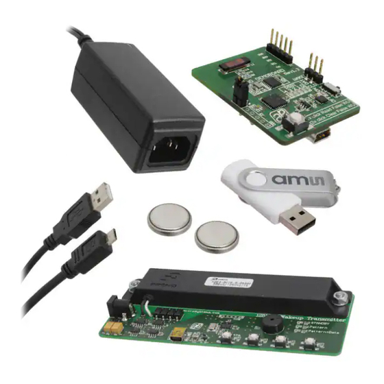
- Page 1 Demo Kit Manual DN[Document ID] AS3930 Standard Board AS3930 DEMOSYSTEM ams Demo Kit Manual, Confidential Page 1 [v1-02] 2014-Jul-10 Document Feedback...
-
Page 2: Table Of Contents
Introduction .......................... 4 Kit Content ........................... 4 Getting Started ........................4 Hardware Description......................5 AS3930 Demoboard Description ..................5 125 kHz Wakeup Transmitter Board ..................6 Software Description ......................7 Install the GUI ........................7 Description of the GUI of the Receiver ................8 4.2.1... - Page 3 Correlator ........................... 12 Schematics, Layers and BOM ................... 13 AS3930 Demoboard Schematic ..................13 AS3930 Demoboard Layout - Top and Bottom Layer ............14 AS3930 Demoboard BOM ....................15 125 kHz Wake-up Transmitter Board Schematic ............... 16 125 kHz Wake-up Transmitter Board Layout ..............17 125 kHz Wake-up Transmitter Board BOM ...............
-
Page 4: Introduction
Insert the +3V Battery at “H” of the AS3930 Demo Board. Turn on the AS3930 Demo Board via the ON/OFF – switch “C”. When turning on the boards all indication-LEDs flash up once. As soon as the AS3930 Demo Board receives a Wake-up Pattern, the RSSI LEDs flash up for 0.5s and show the actual Received Signal Strength. -
Page 5: Hardware Description
AS3930 Standard Board Hardware Description AS3930 Demoboard Description Figure 1: AS3930 Demoboard Description Top and Bottom Figure 2: User Interface Description Label Name Description Info BUTTON 1x short press reads the The number of false wake-ups false wake-ups can be read out and are displayed via the RSSI –... -
Page 6: 125 Khz Wakeup Transmitter Board
Note To establish a connection between the GUI and the AS3930 the board must be RESET by switching the power OFF and ON via “C”. Alternatively, the buttons “A” and “B” can be pressed simultaneously before connecting the USB cable. -
Page 7: Software Description
From the pop up window ‘Choose Plugin’ choose the ‘AS3932_plugin.dll’ Figure 7: Plugin selection Note: Before connecting the 125 kHz Wake-up Transmitter Board with the USB cable press “D” to stop transmitting wake-up patterns. ams Demo Kit Manual, Confidential Page 7 [v1-02] 2014-Jul-10 Document Feedback... -
Page 8: Description Of The Gui Of The Receiver
4.2.1.1 Low Power Mode The AS3930 features two low power modes which can be selected here. By default no power saving mode is enabled. Thus, the receiver channel is active all the time. For the On\Off mode the channel is activated only part of the time to minimize current consumption. For details please see the AS3930 datasheet. -
Page 9: Calibrate Rc Oscillator
The RC oscillator can be calibrated via the microcontroller or the LC antenna. 4.2.1.4 Antenna Damper The antenna can be damped in order to limit the range. Therefore, a resistor inside the AS3930 is switched parallel to the antenna. The value of the resistor can be chosen between 1kΩ to 27kΩ. 4.2.1.5 Gain Reduction The Gain Reduction of the channel amplifier can be selected between 0dB up to -24dB. -
Page 10: General Settings
Enable correlator: If the correlator is enabled the chip searches first for the preamble bits and then for the data pattern (Manchester encoded Wakeup Pattern). Should the pattern correlation be disabled, the AS3930 goes directly in data receiving mode. ... -
Page 11: 4.4.1 Settings Description
AS3932. 4.4.1.4 Enable Buzzer The Wake-up Transmitter Board sends out an acoustic signal whenever a packet is transmitted. This signal can be disabled. ams Demo Kit Manual, Confidential Page 11 [v1-02] 2014-Jul-10 Document Feedback... -
Page 12: Wake-Up Pattern (Manchester)
LEDX RP14 150p 240k CL_DAT RP13 LEDY WAKE WAKE J5 DAT 100n CC7V-T1A VDD_UC VDD_UC VDD_RF VDD_RF Size Project Title Revision AS3930 Demo Board Date 15/02/2013 Originator JRY Sheet ams Demo Kit Manual, Confidential Page 12 [v1-02] 2014-Jul-10 Document Feedback... -
Page 13: As3930 Demoboard Layout - Top And Bottom Layer
AS3930 Standard Board AS3930 Demoboard Layout – Top and Bottom Layer Figure 10: AS3930 Demoboard Layout – Top Layer Figure 11: AS3930 Demoboard Layout – Bottom Layer ams Demo Kit Manual, Confidential Page 13 [v1-02] 2014-Jul-10 Document Feedback... -
Page 14: As3930 Demoboard Bom
AS3930 Standard Board AS3930 Demoboard BOM ams Demo Kit Manual, Confidential Page 14 [v1-02] 2014-Jul-10 Document Feedback... -
Page 15: 125 Khz Wake-Up Transmitter Board Schematic
Sheet 125 kHz Wake-up Transmitter Board Layout Figure 12: 125 kHz Wake-up Transmitter Board Layout – Top Layer Figure 13: 125 kHz Wake-up Transmitter Board Layout – Bottom Layer ams Demo Kit Manual, Confidential Page 15 [v1-02] 2014-Jul-10 Document Feedback... -
Page 16: 125 Khz Wake-Up Transmitter Board Bom
AS3930 Standard Board 125 kHz Wake-up Transmitter Board BOM ams Demo Kit Manual, Confidential Page 16 [v1-02] 2014-Jul-10 Document Feedback... -
Page 17: Ordering & Contact Information
AS3930 Standard Board Ordering & Contact Information Ordering Code Description AS3930 DEMOSYSTEM AS3930 Demo Kit Standard Board Buy our products or get free samples online at: www.ams.com/ICdirect Technical Support is available at: www.ams.com/Technical-Support Provide feedback about this document at: www.ams.com/Document-Feedback For further information and requests, e-mail us at: ams_sales@ams.com... -
Page 18: Copyrights & Disclaimer
AG shall not be liable to recipient or any third party for any damages, including but not limited to personal injury, property damage, loss of profits, loss of use, interruption of business or indirect, special, incidental or consequential damages, of any kind, in connection with or arising out of the furnishing, performance or use of the technical data herein. -
Page 19: Revision Information
Page 1-01 Update to Corporate Format (2013-Mar-11) 1-02 Update to Corporate Format 1-18 Note: Page numbers for the previous version may differ from page numbers in the current revision. ams Demo Kit Manual, Confidential Page 19 [v1-02] 2014-Jul-10 Document Feedback...
Need help?
Do you have a question about the AS3930 and is the answer not in the manual?
Questions and answers