Advertisement
Quick Links
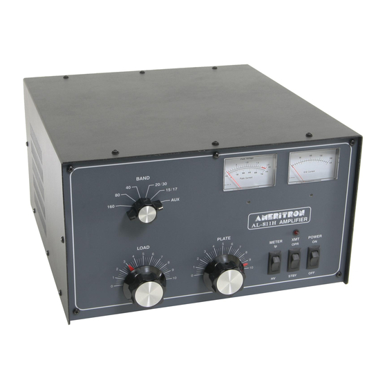
Upgrade Kit AL811 and AL811H amplifier
Copyright W8JI June 2021
Thank you for purchasing this kit (and/or modification manual). These kits and this technical manual are intended
to help fellow Hams understand potential failures. This technical instruction manual and these l kits allow
individuals to bring 811 series amplifiers up to latest revisions. Please order via email links on
www.ctrengineeringinc.com
https://
/ameritron-811-811h-upgrade-kits/
or email order query only to orders@ctrengineeringinc.com
This modification manual is also the result of feedback, questions, and suggestions by fellow Hams. More
suggestions are always welcome. The overriding philosophy is everything reasonably possible should be done to
prevent expensive or annoying damage, especially to expensive radios. An amplifier should work as well as possible
for the cost.
If you use this instruction manual without intention of making your own kit, please PayPal a payment gift of $10 to
w8ji@w8ji.com
These kits comes in two basic forms with one add-on:
(Power Supply rebuild) 811KS
1.) four better sized higher-voltage much longer-life 5000 hours 105c rated electrolytics
2.) four improved bleeder/equalizer resistors
3.) one large 6A grid meter protection diode
4.) four meter multiplier resistors. These resistors also correct a slight meter error
(Protection Kit) 811KP
1.) three application tested GDT tubes
2.) one large 6A meter protection diode
3.) one 100k 2 watt resistor
4.) two 3.9V 5 watt Zener diodes
10-ohm 9-watt CCS 10kV rated fault resistor
5.)
Add on part:
811R200K
200-ohm 25-watt non-inductive load resistor kit with hardware
Information in this modification manual is copyright 2021 by W8JI and CTR Engineering. I understand people like to
share things, but please remember we have several weeks' labor composing this document. Please consider a
PayPal gift to
w8ji@w8ji.com
when using these instructions if you do your own kit.
Overview
I designed the AL811 series many years ago. It was intended to be a minimal cost reasonable power level SSB and
CW only amplifier. The initial design request was for just two tubes, but that obviously would have been
inadequate. As a result I added a third tube as a bare minimum cost amplifier, and pushed to have a better but still
not too expensive four-tube amplifier. The better version became the AL811H.
This instruction manual and the 811 kits are the result of direct feedback from servicing several dozens of
amplifiers. Read these instructions thoroughly before you start working on your amp. Make sure you understand
every step in order to avoid any trouble.
AL811
The three-tube 811 model is not neutralized. As with two unneutralized 572B tubes, three 811A tubes are
Advertisement

Related Manuals for AMERITRON AL811


Summary of Contents for AMERITRON AL811
- Page 1 Overview I designed the AL811 series many years ago. It was intended to be a minimal cost reasonable power level SSB and CW only amplifier. The initial design request was for just two tubes, but that obviously would have been inadequate.
- Page 2 marginally stable. It should really have a 200-ohm cathode swamping resistor, our kit PN 811R200K. This kit has one chassis mount RF-rated 25W resistor, one 0.01uF capacitor, and hardware. In addition you will need a 0.113 to 0.125” (1/8”) drill to add one hole for 4-40 machine screw clearance. AL811H The four tube model is neutralized.
- Page 3 The red line is the primary damaging high frequency arc path. The path goes through tubes, out through the filament coupling capacitors. It then travels through the tuned input circuits to the RF input, and that is where your radio is connected. The arc path is NOT out through the relay control line; a relay line isolation device will not prevent or reduce arc damage.
- Page 4 This reduces the aggravation of protection diode failures Add a 100k resistor from filament to ground, or to a place I provided in later AL811’s that Ameritron for some reason never used. This prevents a weak “popping” noise in your receiver from intermittent gas tube ionization with some GDT’s and tubes...
- Page 5 Fig 3) If you have to drop the back panel, always do this step first. Remove the input switch shaft by ONLY removing the very front screw of the coupling ! The front screw will be a hex or Philips screw normally of standard 6-32 thread. Remember to remove the front screw ONLY! If you remove the rear screw you will have to re-index the rear switch wafer.
- Page 6 Remove the screws and pull the rear panel off the shaft. Do not damage or rotate the blue plastic input switch on the input circuit board. Once you have the panel back and off the shaft lay the panel down as in Fig. 6. You can now remove the shaft from the chassis.
- Page 7 panel. Be careful unsoldering leads. Leads are accessible through a plate on the back of the back panel. Use a large iron, and have a solder sucker or solder wick handy! Use a large hot solder-wetted tip on the wire ends that stick through the boards, so you can get on and off the solder joint quickly.
- Page 8 (Fig. 9) (Fig. 10) Remove MOV’s, do not remove capacitors.
- Page 9 Generation I board: (Fig 11) The Generation I board does NOT have the 24V bias point for the 100K resistor. In these amplifiers the 100K 2- watt resistor goes from anyplace on the filament system to chassis ground. Gen II board: Look for the small capacitor near dual relays (Fig.
- Page 10 (Fig. 12) Gen III board around 2012 (has GDT pads, does not have problem relay line capacitor.): Note this is a board I submitted to MFJ I recommended stopping MOV use. The actual production board may have been altered from this layout once it left my control (Fig 13) This is the working position for all back panels.
- Page 11 All sharp edges on the shaft should be filed or sanded to a radius like this or even slightly more tapered. This will help you slide the shaft back into the switch. It is a few minutes job to fix this now, and it save headaches later.
- Page 12 (Fig. 16) Flip the unit carefully on its side and remove the following screws: (Fig. 17) Lay amplifier down and maneuver tube chassis to reach all sockets. Depending on wiring, the filament leads or red HV choke lead could require removal. The filament leads are supposed to be loosely twisted as the photo shows.
- Page 13 Check all the solder connections carefully. If the plate choke has loose or overlapped wires it needs to be “re-glued”. You can make your own Q-dope from a mix of lacquer thinner or Xylene and white styrofoam “peanuts” used for packing. Dissolve the white packing peanuts or other Styrofoam in thinner until it is a thick paste.
- Page 14 (Fig. 20) (Fig. 21) D16 can be mounted any physical way you like so long as the diode anode is at the center pad and the striped cathode end is toward the rectifier bank and filter capacitor bank negative. This diode allows the any arc energy to get from the chassis to the capacitor bank negative, harmlessly bypassing meters.
- Page 15 I suggest you use one Zener diode in addition to the 6 rectifiers used by Ameritron for a total of about 7.3 volts, or two Zener diodes in series if your amplifier does not have any bias rectifiers.
- Page 16 The diodes can be soldered in by cutting the white wire near the fan. Strip both ends, slide large heat shrink over the white wire well away from the diode(s). Make hook leads in the diodes. Crimp and solder them to make connections. Use either one or two diodes as required. Fig.
- Page 17 (Fig. 23) This kit also includes a small 100K 2-3 watt metal oxide resistor. There are multiple points this resistor can be connected, without a great deal of difference I’ve seen so far. This resistor can go from any tube pin to chassis or from any point on any filament wire to ground. You can even attach it to the Zener mod as shown, since this is a convenient place.
- Page 18 This would be a suitable resistor location on the Zener’s prepped for installation. (Remember one Zener for amplifiers that have a string of bias diodes.) (Fig. 24) There was an intention in revised boards to supply +24 to +30 Vdc as a reference. There is a pick point for this 100K resistor on the later boards.
- Page 19 Early two-relay board with +24V point for resistor (Fig. 26) Zener location, note Zener band is toward the transformer, diode is in air stream. This diode has the 100K resistor elsewhere: (Fig. 27)
Need help?
Do you have a question about the AL811 and is the answer not in the manual?
Questions and answers