Table of Contents
Advertisement
AL-800H Instruction Manual
NEVER APPLY POWER TO THIS AMPLIFIER WITH THE COVER REMOVED!
CONTACT WITH THE VOLTAGES INSIDE THIS AMPLIFIER CAN BE FATAL!
PLEASE READ THIS MANUAL BEFORE ATTEMPING TO OPERATE
EQUIPMENT! Improper or abusive operation of this amplifier can damage the tubes
or other components in this amplifier. Damage caused by improper or abusive
operation is not covered under the warranty policy.
i
WARNING!!
Advertisement
Table of Contents

Related Manuals for AMERITRON Al-800H


Summary of Contents for AMERITRON Al-800H
- Page 1 AL-800H Instruction Manual WARNING!! NEVER APPLY POWER TO THIS AMPLIFIER WITH THE COVER REMOVED! CONTACT WITH THE VOLTAGES INSIDE THIS AMPLIFIER CAN BE FATAL! PLEASE READ THIS MANUAL BEFORE ATTEMPING TO OPERATE EQUIPMENT! Improper or abusive operation of this amplifier can damage the tubes or other components in this amplifier.
-
Page 2: Unpacking Instructions
Remove the 3CX800A7 tubes from their shipping cartons. Carefully unwrap the tubes and inspect them for visible damage. look for dented anode coolers and broken or bent pins. Roll the tubes over slowly and listen for loose internal materials. contact either your Ameritron dealer or Ameritron immediately if any damage exists. -
Page 3: Table Of Contents
AL-800H Instruction Manual Table of Contents Unpacking Instructions ....................iv Features..........................1 AL-800H Technical Specifications .................2 General Information......................3 Safety Interlock....................3 ALC ........................4 Dynamic Bias.......................4 Timer - Overload Circuits....................5 Grid Overload Protection..................5 Thermal Overload....................5 Cathode Warm-up Timer..................5 Power Supply........................6 Heater Supply ......................6 Plate (HV) Supply....................6 Meters ..........................6... - Page 4 Power Supply / SWR Board (50-0800H-1) ............25 Tuned Input Board (50-0800H-2)................26 AL-800H Tuned Input Chart ................26 Meter Board (50-0800H-3)..................26 Timer / Overload Board (50-01172)..............27 AL-800H Main Chassis Parts List ...............28 Frequency Coverage ......................29 Amplifier Tuning Log......................29 Notes:........................30 Schematics ........................31 Wiring Diagram ....................31 PWR Supply / SWR Board..................32...
-
Page 5: Features
A multi-voltage heavy-duty transformer with a unique "buck-boost" winding allows adjustment of the primary voltage to 14 different voltages centered on 115 and 230 volts. This versatile Ameritron feature allows the user to select the optimum primary voltage for maximum performance and life. -
Page 6: Al-800H Technical Specifications
AL-800H Instruction Manual AL-800H Technical Specifications * Input: Circuit type: Pi-network, slug tuned coils Maximum VSWR at resonance: 1.3:1 or less Minimum 2:1 VSWR bandwidth: 20% of center frequency Maximum drive power permissible: 100 watts PEP Typical drive for full power output:... -
Page 7: General Information
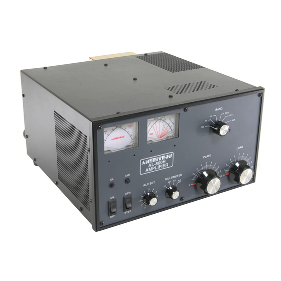
Ameritron Al-800H 1500 Watt Linear Amplifier Instruction Manual The Ameritron AL-800H is a 1500 watt output linear amplifier that operates from 160 through 15 meters. The AL-800HX is the export model that operate from 160 through 10 meters. Export modification instructions are only available with proof of a valid amateur radio license. -
Page 8: Alc
The AL-800H contains an exclusive bias circuit that reduces the idling (quiescent) current very close to the tube's cut off region. The power amplifier tube in the AL-800H has a full resting period of very low dissipation between dots and dashes on CW and between words on SSB. The lower idling current dramatically reduces component temperatures on both CW and SSB. -
Page 9: Timer - Overload Circuits
AL-800H Instruction Manual Timer - Overload Circuits CAUTION: Never modify or disable protection circuits without factory approval. Doing so with void all manufacturer's warranties. Grid Overload Protection This amplifier contains a fast acting electronic grid protection circuit to enhance tube life. The amplifier will quit operating and the "OL"... -
Page 10: Power Supply
AL-800H Instruction Manual Power Supply Heater Supply The heater circuit of this amplifier satisfies all requirements of the tube manufacturer related to tube performance and life. The heater voltage and inrush current are controlled by the power transformer's internal resistance and impedance, heater choke resistance, heater wiring resistance, and the step-start circuit. -
Page 11: Multimeter
"15." Wattmeter Circuit The AL-800H wattmeter circuit uses an accurate directional coupler followed by a true peak detector circuit. This circuit will accurately determine the true peak envelope power (PEP) of normal voice waveforms. If the load SWR is high, the true power reading can be obtained by subtracting the reflected... -
Page 12: Peak Envelope Power Vs. Average Power
This circuit rapidly disables the amplifier when excessive grid dissipation occurs. In the AL-800H a grid current of 150 mA (at 100 watts of drive) produces the maximum rated grid dissipation of 4 watts per tube. This amount of grid current will also safely disable the amplifier within a few milliseconds. -
Page 13: Export Modifications
The use of low quality tubes, tube that have been stored for extended periods, or abused tube will increase the likelihood of a "gas arc". Ameritron recommends using only current code date Eimac 3CX800A7 tubes. -
Page 14: Technical Assistance
Replacement packing materials may be purchased from Ameritron if original packing materials are unavailable or damaged. CAUTION: Never ship this amplifier with the tube installed. Ameritron will not be responsible for shipping damage caused by improper packing. -
Page 15: Installation Guidelines And Suggestions
Power Connections The AL-800H is supplied with a NEMA 6-15P plug for 240 Vac operation. Full duty cycle operation with ac supply voltages below 200 volts is not recommended. The TRANSFORMER CONNECTIONS section on page 13 show the correct wiring for various supply voltages. -
Page 16: Grounding
AL-800H Instruction Manual Grounding Connect a good RF and dc ground to the ground post on the rear panel of the amplifier. Use the heaviest and shortest connection possible. The best materials to use for ground connections are (in order of effectiveness) smooth wide copper flashing, copper tubing, or solid copper wire. -
Page 17: Transformer Connections
JUMPER CONNECTIONS chart for maximum protection. Interconnections Connect the exciter's RF output to the "RF IN" connector on the rear of the AL-800H with 50 ohm coax. Use any good quality 50 ohm cable long enough to connect the amplifier to the exciter. This amplifier connection uses a standard SO-239 female that mates with a PL-259 male connector on the cable. -
Page 18: Operating Instructions And Guidelines
Shielded audio type cable with a standard male phono plug should be used to connect to the "RLY" jack on the AL-800H. This jack has positive 12 Vdc open circuit and supplies 100 mA of current when pulled to ground. The relay circuit has an internal back pulse canceling diode to protect sensitive exciter circuits from damage. -
Page 19: Plate" Control
ALC Metering, Controls, and Adjustments ALC Metering Functions The "MULTIMETER" switch in the AL-800H has two positions that indicate the functioning of the ALC circuit. These positions are as follows: ALC...In this position the multimeter measures the output voltage of the ALC detector. The full scale reading of the ALC detector voltage is 35 volts. -
Page 20: Alc Controls
AL-800H Instruction Manual ALC Controls The position of the "ALC SET" control determines the grid current value that will begin to produce ALC voltage. Rotating the "ALC SET" control counter-clockwise reduces the maximum grid current obtainable and the available RF power output. Rotating the "ALC SET" control clockwise increases the maximum grid current level. -
Page 21: Rear-Panel "Alc Limit" Control
AL-800H Instruction Manual Rear-Panel "ALC LIMIT" Control The "ALC Limit" control (rear panel) limits the maximum voltage available from the ALC circuit. This control is necessary only because the ALC response times and voltage requirements for exciters have never been standardized. The ALC voltage requirements may even vary between different models produced by the same manufacturer. -
Page 22: Driving Power
A second method of determining linear operation is to monitor the peak RF output power carefully on the AL-800H's internal meter. Determine the maximum obtainable RF output power and reduce the exciters power until there is a noticeable margin from the maximum output power. This will insure some reserve power is available for random voice peaks. -
Page 23: Tuning
(clockwise) to prevent excessive voltage and arcing in the tank circuit or excessive grid current. Repeated tripping of the grid overload circuit probably indicates the "LOAD" control is set too low. Set the AL-800H front panel switches as follows: POWER OPR-STBY... - Page 24 AL-800H Instruction Manual Place the amplifier's "BAND" switch on the same band as the exciter. Set the "PLATE" control and the "LOAD" control as indicated below: Frequency Plate Load 1.810 3-1/2 6-1/4 3.600 1-3/4 0-1/2 7.050 1-3/4 10.125 5-1/2 2-1/2 14.050...
- Page 25 AL-800H Instruction Manual > STEPS 10a AND 11a REQUIRE A CONNECTION FROM THE AMPLIFIER'S ALC OUTPUT TO THE EXCITER'S ALC INPUT. > STEPS 10b AND 11b SHOULD BE USED IF THE EXCITER AND AMPLIFIER ALC LINES ARE NOT CONNECTED. NOTE: Step number 10 requires the simultaneous observation of the plate current (Ip) and the grid current (Ig).
-
Page 26: Alc Set" Control
AL-800H Instruction Manual "ALC SET" Control Proper adjustment of the front panel "ALC SET" control accomplishes the following: The exciter's power is limited to a value that will produce a fixed amount of grid current in the amplifier. The front panel "ALC SET" control determines the maximum grid current that can be produced. -
Page 27: Fm (Frequency Modulation), Rtty, And Digital Operation
QSK-5 unit. The QSK-5 operates directly from 120 Vac power lines. Ameritron also offers an internal QSK board as a space-saver for the AL-800H. This internal board is slightly less expensive. However, it provides less flexibility and serviceability than the external QSK-5 unit. -
Page 28: Periodic Maintenance
ALWAYS be cautious of heat. Many components inside the amplifier operate at high temperatures. NEVER make any unauthorized component or circuit modifications to this product. The only acceptable source for modifications is Ameritron or a source approved by Ameritron. Unauthorized modifications almost certainly will increase the risk of equipment failure or personal injury. -
Page 29: Parts List
AL-800H Instruction Manual Parts List Power Supply / SWR Board (50-0800H-1) Designator Description Ameritron P/N D101, 102, 114, 115 1N34A 300-0346 D103 1N752 Zener 5.6V 305-0710 D116 - 120 1N4001 300-0266 D104 - 113 1N5408 300-0145 C101 27 pF 500 V... -
Page 30: Tuned Input Board (50-0800H-2)
C214 150pF capacitor 208-5151 C215 220pF capacitor 2085171 L201 See input chart See input chart S201 Input switch 500-4811 AL-800H Tuned Input Chart BAND C201 (pF) tube side L201 C201 (pF) transmitter side 2700 (208-5689)* 21.75 (405-1217) 2000 (208-5608) 1300 (208-5177) 18.75... -
Page 31: Timer / Overload Board (50-01172)
AL-800H Instruction Manual Timer / Overload Board (50-0117-2) Designator Description Ameritron P/N C501-506 .01 uF 50 V disc 200-0416 C507,508 .47 uF tantalum 203-0530 C509 100 uF 25 V 203-0564 D501, 502 1N4001 300-0266 D503 5.6 V zener 301-710 IC501... -
Page 32: Al-800H Main Chassis Parts List
AL-800H Instruction Manual AL-800H Main Chassis Parts List Designator Description Ameritron P/N Blower (Howard 3-90-8538) 410-3590 C1, 6 170 pF Doorknob 7.5 kV 209-0559 C2, 3, 9, 20 .001 uF 7.5 kV 200-7224 C4, 5 470 pF 3 kV chip capacitor... -
Page 33: Frequency Coverage
AL-800H Instruction Manual Frequency Coverage AL-800H AL-800HX 160 meters 1.8-2.0 MHz 160 meters 1.8-2.0 MHz 80 meters 3.3-4.4 MHz 80 meters 3.3-4.4 MHz 40 meters 6.3-8.3 MHz 40 meters 6.3-8.3 MHz 20 meters 10.1-15.5 MHz 20 meters 10.1-15.5 MHz 15 meters 16.5-21.5 MHz*... -
Page 34: Notes
AL-800H Instruction Manual Notes:...
Need help?
Do you have a question about the Al-800H and is the answer not in the manual?
Questions and answers