Table of Contents
Advertisement
Quick Links
Advertisement
Table of Contents
Troubleshooting

Related Manuals for ZyXEL Communications SBG5500 Series


Summary of Contents for ZyXEL Communications SBG5500 Series
- Page 1 User’s Guide SBG5500/3310 Series SBG5500-A/SBG5500-B/SBG3310-A Small Business Gateway Default Login Details Version 1.12 Edition 1, 04/2018 LAN IP Address http://192.168.1.1 User Name admin Password 1234 Copyright © 2018 Zyxel Communications Corporation...
- Page 2 IMPORTANT! READ CAREFULLY BEFORE USE. KEEP THIS GUIDE FOR FUTURE REFERENCE. This is a User’s Guide for a series of products. Not all products support all firmware features. Screenshots and graphics in this book may differ slightly from your product due to differences in your product firmware or your computer operating system.
-
Page 3: Document Conventions
Document Conventions Warnings and Notes These are how warnings and notes are shown in this guide. Warnings tell you about things that could harm you or your device. Note: Notes tell you other important information (for example, other things you may need to configure or helpful tips) or recommendations. -
Page 4: Table Of Contents
Contents Overview Contents Overview User’s Guide ............................12 Introducing the SBG ..........................13 The Web Configurator ......................... 20 Wizard ..............................27 Technical Reference ........................45 Dashboard ............................46 WAN/Internet ............................49 LAN ................................. 86 Routing ..............................109 Network Address Translation (NAT) ....................123 Firewall .............................. -
Page 5: Table Of Contents
Table of Contents Table of Contents Document Conventions ........................3 Contents Overview ..........................4 Table of Contents ..........................5 Part I: User’s Guide..................12 Chapter 1 Introducing the SBG...........................13 1.1 Overview ............................13 1.2 Ways to Manage the SBG ......................14 1.3 Good Habits for Managing the SBG .................... 14 1.4 Applications for the SBG ........................ - Page 6 Table of Contents Part II: Technical Reference................45 Chapter 4 Dashboard ............................46 4.1 Overview ............................46 4.2 The Dashboard Screen ........................46 Chapter 5 WAN/Internet............................49 5.1 Overview ............................49 5.1.1 What You Can Do in this Chapter ..................50 5.1.2 What You Need to Know ..................... 50 5.1.3 Before You Begin ........................
- Page 7 Table of Contents 6.7 The VLAN / Interface Group Screen .................... 99 6.7.1 VLAN / Interface Group: Add/Edit ..................100 6.8 The DNS Entry Screen ........................104 6.9 The DNS Forwarder Screen ......................104 6.9.1 DNS Forwarder: Add/Edit ....................105 6.10 Technical Reference ........................
- Page 8 Table of Contents 9.1 Overview ............................139 9.1.1 What You Can Do in this Chapter ..................139 9.1.2 What You Need to Know ....................140 9.2 The Firewall Overview Screen ..................... 141 9.3 The DoS Screen ..........................141 9.4 The Firewall Rules Screen ......................142 9.4.1 Firewall Rule: Add/Edit ......................
- Page 9 Table of Contents 10.9.3 IKE Phases .......................... 188 10.9.4 Negotiation Mode ......................189 10.9.5 IPsec and NAT ........................190 10.9.6 VPN, NAT, and NAT Traversal ................... 190 10.9.7 ID Type and Content ......................191 10.9.8 Pre-Shared Key ........................192 10.9.9 Diffie-Hellman (DH) Key Groups ..................192 Chapter 11 Bandwidth Management ........................194 11.1 Overview .............................
- Page 10 Table of Contents 14.1 Overview ............................. 227 14.2 The License Screen ........................227 Chapter 15 Device Name ...........................229 15.1 Overview ............................. 229 15.2 The Device Name Screen ......................229 Chapter 16 Host Name List ..........................231 16.1 Overview ............................. 231 16.2 The Host Name List Screen ......................231 16.2.1 Add Host Name .........................
- Page 11 Table of Contents 21.1 Overview ............................. 247 21.2 The Firmware Screen ........................247 21.3 The Mobile Profile Screen ......................249 Chapter 22 Backup / Restore ..........................251 22.1 Overview ............................. 251 22.2 The Backup / Restore Screen ....................251 Chapter 23 Language ............................253 23.1 Overview .............................
-
Page 12: User's Guide
User’s Guide... -
Page 13: Introducing The Sbg
H A P T E R Introducing the SBG 1.1 Overview This chapter introduces the main features and applications of the SBG. The SBG5500/3310 Series consists of the following models: • SBG5500-A • SBG5500-B • SBG3310-A The SBG is a VDSL router and Gigabit Ethernet (GbE) gateway. It has one DSL port and Gigabit Ethernet for super-fast Internet access over telephone lines. -
Page 14: Ways To Manage The Sbg
Chapter 1 Introducing the SBG 1.2 Ways to Manage the SBG Use any of the following methods to manage the SBG. • Web Configurator. This is recommended for everyday management of the SBG using a (supported) web browser. 1.3 Good Habits for Managing the SBG Do the following things regularly to make the SBG more secure and to manage the SBG more effectively. - Page 15 Chapter 1 Introducing the SBG Computers can connect to the SBG’s LAN ports. Figure 1 SBG’s Internet Access Application: ADSL/VDSL Figure 2 SBG’s Internet Access Application: ADSL Figure 3 SBG5500’s Internet Access Application: 3G/4G WAN Backup You can also configure IP filtering on the SBG for secure Internet access. When the IP filter is on, all incoming traffic from the Internet to your network is blocked by default unless it is initiated from your network.
-
Page 16: Sbg's Usb Support
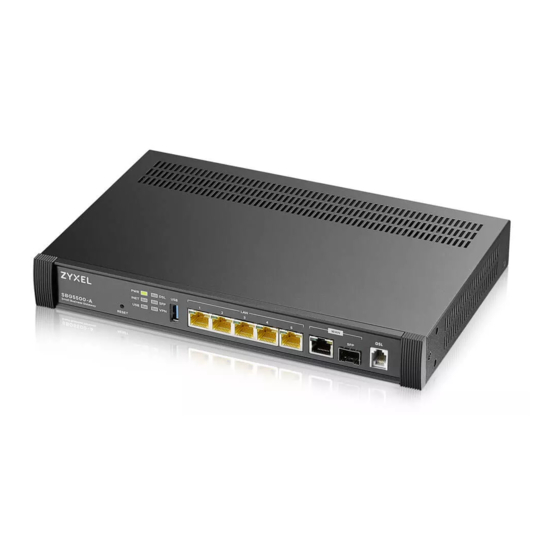
Chapter 1 Introducing the SBG 1.4.2 SBG’s USB Support Use the USB port for file sharing or insert a 3G/4G dongle for cellular backup WAN (Internet) connections. File Sharing Use the USB port (built-in USB 2.0) to share files on USB memory sticks or USB hard drives (B). Use FTP to access the files on the USB device. - Page 17 Figure 6 SBG5500-B Front and Rear Panels None of the LEDs are on if the SBG is not receiving power. The location of the LEDs are highlighted in the figures above. The following table describes the LED behavior of the SBG5500 Series. Table 2 LED Descriptions...
- Page 18 Chapter 1 Introducing the SBG Table 2 LED Descriptions (continued) COLOR STATUS DESCRIPTION ETHERNET Green The SBG has a successful Ethernet connection with a device on the Local LAN 1-4 (On Area Network (LAN). (Left LED) Connector) Blinking The SBG is sending or receiving data to/from the LAN. The SBG does not have an Ethernet connection with the LAN.
-
Page 19: The Reset Button
Chapter 1 Introducing the SBG Table 3 LED Descriptions (continued) COLOR STATUS DESCRIPTION Green The VPN2S has a successful Ethernet connection on the WAN. Blinking The VPN2S is sending or receiving data to/from the WAN. There is no Ethernet connection on the WAN. INTERNET Green The SBG has an IP connection but no traffic. -
Page 20: The Web Configurator
H A P T E R The Web Configurator 2.1 Overview The web configurator is an HTML-based management interface that allows easy device setup and management via Internet browser. Use Internet Explorer 10.0 and later versions, Mozilla Firefox, Google Chrome, and Safari latest versions. The recommended screen resolution is 1024 by 768 pixels. In order to use the web configurator you need to allow: •... - Page 21 Chapter 2 The Web Configurator The following screen displays if you have not yet changed your password from the default. Enter a new password, retype it to confirm and click Apply. After changing the password your SBG will log out automatically.
-
Page 22: Web Configurator Layout
Chapter 2 The Web Configurator 2.2 Web Configurator Layout Figure 11 Screen Layout The main screen is divided into these parts: • A - title bar • B - navigation panel • C - main window 2.2.1 Title Bar The title bar provides some icons in the upper right corner. The icons provide the following functions. -
Page 23: Navigation Panel
Statistics Use this screen to view detailed DSL traffic statistics. SFP Status Use this screen to view details about the SFP connection. (SBG5500 Series only) WAN Setup Use this screen to view and configure ISP parameters, WAN IP address assignment, and other advanced properties. - Page 24 Chapter 2 The Web Configurator Table 5 Navigation Panel Summary (continued) LINK FUNCTION Use this screen to view and configure domain zone forwarder on the SBG. Forwarder Routing Routing Use this screen to view the IPv4 and IPv6 routing flow. Status Policy Route Use this screen to view and set up policy routes on the SBG.
-
Page 25: Main Window
Chapter 2 The Web Configurator Table 5 Navigation Panel Summary (continued) LINK FUNCTION General Use this screen to enable QoS and traffic prioritizing. You can also configure the QoS rules and actions. Queue Setup Use this screen to configure QoS queues. Classification Use this screen to define a classifier. - Page 26 Chapter 2 The Web Configurator Figure 12 Dashboard Screen SBG5500/3310 Series User’s Guide...
-
Page 27: Wizard
H A P T E R Wizard 3.1 Overview The Web Configurator's quick setup Wizard helps you configure Internet and VPN connection settings. This chapter provides information on configuring the Wizard screens in the Web Configurator. See the feature-specific chapters in this User’s Guide for background information. Before you begin configuring your SBG register your device at myZyxel portal and check your current license status. -
Page 28: Wizard Basic Setup
Chapter 3 Wizard 3.2 Wizard Basic Setup The Wizard appears automatically after you log in the first time. Or you can go to the Wizard tab in the navigation panel. Click the Welcome to Basic Setup down arrow to configure an interface to connect to the Internet. - Page 29 Chapter 3 Wizard Figure 15 Connect to the Internet If you select the ADSL over ATM connection type, enter the VPI and VCI assigned to you and the method of multiplexing used by your ISP. Figure 16 ATM PVC Configuration SBG5500/3310 Series User’s Guide...
- Page 30 Chapter 3 Wizard If you select PPPoE or PPPoA as your encapsulation, type the Username given to you by your ISP and type the Password associated with the user name. Figure 17 PPP information Use this screen to specify which IPv4 address the SBG uses to connect to the Internet. If your ISP gave you this information, enter it here.
- Page 31 Chapter 3 Wizard Figure 19 DNS Server Choose the time zone for your device’s location. Click Save. Figure 20 Date and Time The SBG saves your settings and attempts to connect to the Internet. If the SBG failed to connect to the Internet or if you want to modify any of the settings you previously configured you can click Back or go to the Configuration >...
- Page 32 Chapter 3 Wizard Figure 21 Basic Setup Completed You can register your device and manage subscription services available for your SBG at myZyxel portal for online services. Figure 22 Register Device and Services Once you completed the basic setup a summary of your settings displays. Click Finish to continue with the Wizard setup.
-
Page 33: Wizard Ipsec Vpn Setup
Chapter 3 Wizard Figure 23 Summary 3.3 Wizard IPsec VPN Setup Click the IPsec VPN Setup down arrow to configure a VPN (Virtual Private Network) rule for a secure connection to another computer or network. Figure 24 Wizard IPsec VPN Setup There are two types of VPN policies you can configure in the SBG. -
Page 34: Vpn Express Settings
Chapter 3 Wizard • Advanced - Select Advanced to change default settings an/or use certificates instead of a pre- shared key in the VPN rule. See Section 3.3.2 on page Figure 25 VPN Policy Type 3.3.1 VPN Express Settings The following screens will display if you select Express in the previous screen. Type the Rule Name used to identify this VPN connection (and VPN gateway). - Page 35 Chapter 3 Wizard Figure 26 VPN Express Settings In My Interface select the type of encapsulation this connection is to use. Configure a Secure Gateway IP as the peer SBG’s WAN IP address. Type a secure Pre-Shared Key. Set Local Policy to be the IP address range of the network connected to the SBG and Remote Policy to be the IP address range of the network connected to the peer SBG.
-
Page 36: Vpn Advanced Settings
Chapter 3 Wizard This screen shows a read-only summary of the VPN tunnel’s configuration. Click Save to apply your changes. Figure 28 Summary Your SBG saves your settings. Now the VPN rule is configured on the SBG. Figure 29 VPN Express Settings Completed 3.3.2 VPN Advanced Settings The following screens will display if you select Advanced in the VPN Policy screen. - Page 37 Chapter 3 Wizard Figure 30 VPN Advanced Settings Use the following screen to setup Phase 1 Settings. Select an Encryption, Authentication Algorithm, and Key Group, and define how often the SBG renegotiates the IKE SA in the Life Time field. For more information on each label see Section 10.5 on page 164.
- Page 38 Chapter 3 Wizard Figure 31 Phase 1 Settings Use the following screen to setup Phase 2 Settings. Phase 2 in an IKE uses the SA that was established in phase1 to negotiate Security Associations (SAs) for IPsec. For more information on each label on this screen see Section 10.5 on page 164.
- Page 39 Chapter 3 Wizard Figure 32 Phase 2 Settings A read-only summary of the VPN tunnel’s configuration will display. If you want to save your changes click Save; otherwise go Back to modify any previous configurations. SBG5500/3310 Series User’s Guide...
- Page 40 Chapter 3 Wizard Figure 33 Summary Your SBG saves your settings. Now the rule is configured on the SBG. Click Finish to exit the VPN Setup Wizard. SBG5500/3310 Series User’s Guide...
-
Page 41: Wizard Ipv6 Setup
Chapter 3 Wizard Figure 34 VPN Advanced Settings Completed 3.4 Wizard IPv6 Setup Click the IPv6 Setup down arrow to configure the IPv6 settings on the SBG. Click Next to continue the Wizard, Back to return to the previous screen. SBG5500/3310 Series User’s Guide... - Page 42 Chapter 3 Wizard Figure 35 Wizard IPv6 Setup Select the WAN interface on which you want to have an IPv6 connection. Select Auto Detection for the SBG to automatically detect the IPv6 Internet connection type, and the Wizard IPv6 setup is completed. If you want to enter a static IPv6 address or obtain it from a DHCP server click Next.
- Page 43 Chapter 3 Wizard Figure 37 WAN Setup Use this screen to configure the LAN IPv6 settings of the SBG. Select Delegate Prefix From WAN to automatically obtain an IPv6 network prefix from the previously selected interface. Or select Static to configure a static IPv6 address for the SBG’s LAN IPv6 address.
- Page 44 Chapter 3 Wizard A read-only summary of the IPv6 settings will display. Click Finish to exit the Wizard IPv6 Setup. Figure 39 Summary SBG5500/3310 Series User’s Guide...
-
Page 45: Technical Reference
Technical Reference... -
Page 46: Dashboard
H A P T E R Dashboard 4.1 Overview After you log into the Web Configurator, the Dashboard screen appears. This shows the network connection status of the SBG and clients connected to it. You can use the Dashboard screen to look at the current status of the SBG, system resources, and interfaces (LAN and WAN). - Page 47 Chapter 4 Dashboard Figure 41 Dashboard List View Screen Each field is described in the following table. Table 6 Dashboard List View Screen LABEL DESCRIPTION Device Information Host Name This field displays the name used to identify the SBG on any network. Serial Number This field displays the serial number of this SBG.
- Page 48 Chapter 4 Dashboard Table 6 Dashboard List View Screen LABEL DESCRIPTION Failover This field displays the passive interfaces used for failover in the SBG. VPN Status This field displays the SBG’s VPN connections and if the IP Sec SA is connected or disconnected.
-
Page 49: Wan/Internet
H A P T E R WAN/Internet 5.1 Overview This chapter discusses the SBG’s WAN/Internet screens. Use these screens to configure your SBG for Internet access. A WAN (Wide Area Network) connection is an outside connection to another network or the Internet. It connects your private networks, such as a LAN (Local Area Network) and other networks, so that a computer in one location can communicate with computers in other locations. -
Page 50: What You Can Do In This Chapter
Chapter 5 WAN/Internet 5.1.1 What You Can Do in this Chapter • Use the WAN Status screen to view the WAN traffic statistics (Section 5.3 on page 57). • Use the WAN Setup screen to view, remove or add a WAN interface. You can also configure the WAN settings on the SBG for Internet access (Section 5.3 on page 57). - Page 51 Chapter 5 WAN/Internet (Internet Service Provider). If your ISP offers a dial-up Internet connection using PPPoE (PPP over Ethernet), they should also provide a username and password (and service name) for user authentication. WAN IP Address The WAN IP address is an IP address for the SBG, which makes it accessible from an outside network. It is used by the SBG to communicate with other devices in other networks.
- Page 52 Chapter 5 WAN/Internet • Any number of consecutive blocks of zeros can be replaced by a double colon. A double colon can only appear once in an IPv6 address. So 2001:0db8:0000:0000:1a2f:0000:0000:0015 can be written as 2001:0db8::1a2f:0000:0000:0015, 2001:0db8:0000:0000:1a2f::0015, 2001:db8::1a2f:0:0:15 or 2001:db8:0:0:1a2f::15. IPv6 Prefix and Prefix Length Similar to an IPv4 subnet mask, IPv6 uses an address prefix to represent the network address.
-
Page 53: Before You Begin
Chapter 5 WAN/Internet Dual Stack Lite Use Dual Stack Lite when local network computers use IPv4 and the ISP has an IPv6 network. When the SBG has an IPv6 WAN address and you set IPv4/IPv6 Mode to IPv6 Only, you can enable Dual Stack Lite to use IPv4 computers and services. -
Page 54: The Xdsl Statistics Screen
Chapter 5 WAN/Internet The following table describes the labels in this screen. Table 8 Configuration > WAN / Internet > WAN Status LABEL DESCRIPTION Name This displays the name of the WAN interface. Status This shows Up if the connection to this interface is up, otherwise it will display Down. Tx Bytes This indicates the number of bytes transmitted on this interface. - Page 55 Chapter 5 WAN/Internet The following table describes the labels in this screen. Table 9 Configuration > WAN / Internet > WAN Status > xDSL Statistics LABEL DESCRIPTION Refresh Click this to refresh the statistics. xDSL Training Status This displays the current state of setting up the DSL connection. Mode This displays the ITU standard used for this connection.
-
Page 56: The Sfp Status Screen
View operating parameters within the fiber link. Click Configuration > WAN / Internet > WAN Status and click on the SFP Status tab. Note: This screen is only available in the SBG5500 Series. Figure 48 Configuration > WAN / Internet > WAN Status > SFP Status... -
Page 57: The Wan Setup Screen
Chapter 5 WAN/Internet The following table describes the labels in this screen. Table 10 Configuration > WAN / Internet > WAN Status > SFP Status LABEL DESCRIPTION Refresh Click Refresh to update this screen. Transceiver Information Status This field displays the status of the SFP transceiver. Vendor This field displays the SFP transceiver’s vendor name. -
Page 58: Internet Connection: Add/Edit
Chapter 5 WAN/Internet Table 11 Configuration > WAN / Internet > WAN Setup (continued) LABEL DESCRIPTION Multiple Entries Select one or more WAN connections and click this to enable them. Turn On Use the [Shift] or [Ctrl] key to select multiple entries. Multiple Entries Select one or more WAN connections and click this to disable them. - Page 59 Chapter 5 WAN/Internet Figure 50 WAN / Internet > WAN Setup > Add/Edit: Routing Mode SBG5500/3310 Series User’s Guide...
- Page 60 Chapter 5 WAN/Internet The following table describes the labels in this screen. Table 12 WAN Internet > WAN Setup > Add/Edit: Routing Mode LABEL DESCRIPTION General Interface Select this to activate the WAN configuration settings. Enable Name Specify a descriptive name for this connection. Type Select whether it is ADSL/VDSL over PTM, ADSL over ATM, or Ethernet connection.
- Page 61 Chapter 5 WAN/Internet Table 12 WAN Internet > WAN Setup > Add/Edit: Routing Mode (continued) LABEL DESCRIPTION The valid range for the VCI is 32 to 65535 (0 to 31 is reserved for local management of ATM traffic). Enter the VCI assigned to you. Encapsulation Select the method of multiplexing used by your ISP from the drop-down list box.
- Page 62 Chapter 5 WAN/Internet Table 12 WAN Internet > WAN Setup > Add/Edit: Routing Mode (continued) LABEL DESCRIPTION DNS Server This is available only when you select IPv4 Only or IPv4 IPv6 Dualstack in the IPv4 / IPv6 Mode field. Obtain DNS Select this if you want the SBG to use the DNS server addresses assigned by your ISP.
- Page 63 Chapter 5 WAN/Internet Table 12 WAN Internet > WAN Setup > Add/Edit: Routing Mode (continued) LABEL DESCRIPTION Automatically Select this to have the SBG detect IPv4 address automatically through DHCP. configured by This option is configurable only when you set the method of encapsulation to IPoE. DHCPC Manual Select this to manually configure an IPv4 address of the relay server.
- Page 64 Chapter 5 WAN/Internet Table 12 WAN Internet > WAN Setup > Add/Edit: Routing Mode (continued) LABEL DESCRIPTION Check Default Select this to use the default gateway for the connectivity check. Gateway Check This Select this to specify a domain name or IP address for the connectivity check. Enter that domain Address name or IP address in the field next to it.
- Page 65 Chapter 5 WAN/Internet The following table describes the fields in this screen. Table 13 WAN / Internet > WAN Setup > Add/Edit: Bridge Mode (ADSL/VDSL over PTM or Ethernet) LABEL DESCRIPTION General Interface Enable Select this to activate the WAN configuration settings. Name Enter a service name of the connection.
- Page 66 Chapter 5 WAN/Internet Figure 52 WAN / Internet > WAN Setup > Add/Edit: Bridge Mode (ADSL over ATM) The following table describes the fields in this screen. Table 14 WAN / Internet > WAN Setup > Add/Edit: Bridge Mode (ADSL over ATM) LABEL DESCRIPTION General...
- Page 67 Chapter 5 WAN/Internet Table 14 WAN / Internet > WAN Setup > Add/Edit: Bridge Mode (ADSL over ATM) (continued) LABEL DESCRIPTION Encapsulation Select the method of multiplexing used by your ISP from the drop-down list box. Choices are: • LLC/SNAP-BRIDGING: In LCC encapsulation, bridged PDUs are encapsulated by identifying the type of the bridged media in the SNAP header.
- Page 68 Chapter 5 WAN/Internet Figure 53 WAN / Internet > WAN Setup > IPv6 The following table describes the labels in this screen. Table 15 WAN / Internet > WAN Setup > IPv6 LABEL DESCRIPTION IPv6 Address Obtain an IPv6 Address Select this if you want to have the SBG use the IPv6 prefix from the connected Automatically router’s Router Advertisement (RA) to generate an IPv6 address.
-
Page 69: The Mobile Screen
Chapter 5 WAN/Internet Table 15 WAN / Internet > WAN Setup > IPv6 LABEL DESCRIPTION DNS Server 1 Enter the first IPv6 DNS server address assigned by the ISP. DNS Server 2 Enter the second IPv6 DNS server address assigned by the ISP. Tunnel (This is available only when you select IPv6 Only in the IPv4 / IPv6 Mode field.) Enable DS-Lite... - Page 70 Chapter 5 WAN/Internet Figure 54 Configuration > WAN / Internet > Mobile SBG5500/3310 Series User’s Guide...
- Page 71 Chapter 5 WAN/Internet The following table describes the labels in this screen. Table 16 Configuration > WAN / Internet > Mobile LABEL DESCRIPTION 3G Connection Settings Card This field displays the manufacturer and model name of your 3G/4G card if you inserted one in Description the SBG.
- Page 72 Chapter 5 WAN/Internet Table 16 Configuration > WAN / Internet > Mobile (continued) LABEL DESCRIPTION Connectivity The interface can regularly check the connection to the gateway you specified to make sure it Check is still available. You specify how often the interface checks the connection, how long to wait for a response before the attempt is a failure, and how many consecutive failures are required before the SBG stops routing to the gateway.
-
Page 73: The Port Setting Screen
Chapter 5 WAN/Internet Table 16 Configuration > WAN / Internet > Mobile (continued) LABEL DESCRIPTION Enable Log Select this to activate the logging function at the interval you set in the Interval field. Interval Enter the time interval (in minutes) at which the SBG creates log messages. When Over Specify the actions the SBG takes when the time or data limit is exceeded. -
Page 74: The Multi-Wan Screen
Chapter 5 WAN/Internet Click Apply to save your changes and apply them to the SBG. Click Reset to change the port groups to their current configuration (last-saved values). 5.6 The Multi-WAN Screen Use the Multi-WAN screen to configure the multiple WAN load balance and failover rules to distribute traffic among different interfaces. -
Page 75: Multi-Wan: Edit
Chapter 5 WAN/Internet 5.6.1 Multi-WAN: Edit Select an existing multi-WAN and click Edit in the Multi-WAN screen to configure it. Figure 57 Multi-WAN: Edit The following table describes the labels in this screen. Table 18 Multi-WAN: Edit LABEL DESCRIPTION Name This field displays the label to identify the trunk. -
Page 76: How To Configure Multi-Wan For Load Balancing And Failover
Chapter 5 WAN/Internet Table 18 Multi-WAN: Edit (continued) LABEL DESCRIPTION Move To move an interface to a different number in the list, click the Move icon. In the field that appears, specify the number to which you want to move the interface. This column displays the priorities of the group’s interfaces. -
Page 77: The Dynamic Dns Screen
Chapter 5 WAN/Internet 5.6.2.1 Configuring Multi-WAN Click Configuration > WAN / Internet > Multi-WAN > Edit. By default, all available WAN connections on the SBG are in active mode with a weight of 1, except for the mobile WAN connection which is set to passive mode. -
Page 78: Dynamic Dns: Add/Edit
Chapter 5 WAN/Internet Figure 58 Configuration > WAN / Internet > Dynamic DNS The following table describes the labels in this screen. Table 19 Configuration > WAN / Internet > Dynamic DNS LABEL DESCRIPTION Dynamic DNS Click this to add a dynamic DNS. Edit Select an entry and click Edit to modify the dynamic DNS’s settings. - Page 79 Chapter 5 WAN/Internet Figure 59 Dynamic DNS: Add/Edit The following table describes the labels on this screen. Table 20 Dynamic DNS: Add/Edit LABEL DESCRIPTION Enable Select Enable to use this dynamic DNS. General Profile Name When you are adding a dynamic DNS entry, type a descriptive name for this DDNS entry in the SBG.
-
Page 80: The Xdsl Advanced Screen
Chapter 5 WAN/Internet Table 20 Dynamic DNS: Add/Edit LABEL DESCRIPTION Click OK to save your changes back to the SBG and exit this screen. Cancel Click Cancel to exit this screen without saving. 5.8 The xDSL Advanced screen Use the xDSL Advanced screen to enable or disable PTM over ADSL, Annex M, and DSL PhyR functions. The SBG supports the PhyR retransmission scheme. - Page 81 US0, 30a, 35b The SBG must comply with at least one profile specified in G.993.2. but compliance with more than one profile is allowed. Note: 30a and 35b are only supported by the SBG5500 Series. SBG5500/3310 Series User’s Guide...
-
Page 82: Technical Reference
Chapter 5 WAN/Internet Table 21 Configuration > WAN / Internet > xDSL Advanced (continued) LABEL DESCRIPTION Apply Click Apply to save your changes back to the SBG. Reset Click this button to return the screen to its last-saved settings. 5.9 Technical Reference The following section contains additional technical information about the SBG features described in this chapter. - Page 83 Chapter 5 WAN/Internet ATM Traffic Classes These are the basic ATM traffic classes defined by the ATM Forum Traffic Management 4.0 Specification. Constant Bit Rate (CBR) Constant Bit Rate (CBR) provides fixed bandwidth that is always available even if no data is being sent. CBR traffic is generally time-sensitive (doesn't tolerate delay).
- Page 84 Chapter 5 WAN/Internet VLAN also increases network performance by limiting broadcasts to a smaller and more manageable logical broadcast domain. In traditional switched environments, all broadcast packets go to each and every individual port. With VLAN, all broadcasts are confined to a specific broadcast domain. Introduction to IEEE 802.1Q Tagged VLAN A tagged VLAN uses an explicit tag (VLAN ID) in the MAC header to identify the VLAN membership of a frame across bridges - they are not confined to the switch on which they were created.
- Page 85 Chapter 5 WAN/Internet The ISP tells you the DNS server addresses, usually in the form of an information sheet, when you sign up. If your ISP gives you DNS server addresses, manually enter them in the DNS server fields. If your ISP dynamically assigns the DNS server IP addresses (along with the SBG’s WAN IP address), set the DNS server fields to get the DNS server address from the ISP.
-
Page 86: Lan
H A P T E R 6.1 Overview A Local Area Network (LAN) is a shared communication system to which many networking devices are connected. It is usually located in one immediate area such as a building or floor of a building. Use the LAN screens to help you configure a LAN DHCP server and manage IP addresses. -
Page 87: What You Need To Know
Chapter 6 LAN 6.1.2 What You Need To Know 6.1.2.1 About LAN IP Address IP addresses identify individual devices on a network. Every networking device (including computers, servers, routers, printers, etc.) needs an IP address to communicate across the network. These networking devices are also known as hosts. -
Page 88: Before You Begin
Chapter 6 LAN 6.1.3 Before You Begin Find out the MAC addresses of your network devices if you intend to add them to the DHCP Client List screen. 6.2 The LAN Status Screen Use the LAN Status Screen to view the status of all interfaces connected to the SBG, details about DHCP clients. -
Page 89: The Lan Setup Screen
Chapter 6 LAN Table 22 Configuration > LAN / Home Network > LAN Status LABEL DESCRIPTION IP Address This field displays the DHCP client’s IP address. MAC Address This field displays the MAC address to which the IP address is currently assigned or for which the IP address is reserved. -
Page 90: Lan Setup: Edit
Chapter 6 LAN Table 23 Configuration > LAN / Home Network > LAN Setup LABEL DESCRIPTION DHCP This shows whether the SBG acts as DHCP Server or DHCP Relay agent. It shows Disable if the DHCP server has been stopped in the SBG. IPv6 This shows the IPv6 prefix and prefix length you configured when you enable IPv6 on the LAN interface and set... - Page 91 Chapter 6 LAN The following table describes the fields in this screen. Table 24 LAN Setup: Edit > General / IPv4 LABEL DESCRIPTION General Group Name Select the interface group name for which you want to configure LAN settings. See Section 6.7 on page 99 for how to create a new interface group/VLAN.
-
Page 92: Lan Setup Ipv6: Edit
Chapter 6 LAN Table 24 LAN Setup: Edit > General / IPv4 (continued) LABEL DESCRIPTION DNS Server 2 Specify the IP address of the secondary DNS server for the DHCP clients to use. Use one of the following ways to specify the IP address. DNS Proxy - the clients use the IP address of the SBG LAN interface. - Page 93 Chapter 6 LAN Figure 64 LAN Setup: Edit > IPv6 The following table describes the labels in this screen. Table 25 Configuration > LAN / Home Network > LAN Setup: Edit > IPv6 LABEL DESCRIPTION Link Local Address Static IPv6 Address Prefix This shows the static IPv6 address prefix used to represent the SBG network address.
- Page 94 Chapter 6 LAN Table 25 Configuration > LAN / Home Network > LAN Setup: Edit > IPv6 LABEL DESCRIPTION Static Select this option to configure a fixed IPv6 address for the SBG’s LAN interface. Note: This fixed address is for local hosts to access the Web Configurator only as the global LAN IPv6 address might be changed by your ISP any time.
-
Page 95: The Static Dhcp Screen
Chapter 6 LAN 6.4 The Static DHCP Screen This table allows you to assign IP addresses on the LAN to specific individual computers based on their MAC Addresses. Every Ethernet device has a unique MAC (Media Access Control) address. The MAC address is assigned at the factory and consists of six pairs of hexadecimal characters, for example, 00:A0:C5:00:00:02. - Page 96 Chapter 6 LAN Figure 66 Static DHCP: Add/Edit The following table describes the labels in this screen. Table 27 Static DHCP: Add/Edit LABEL DESCRIPTION Static DHCP Configuration Enable Select this to activate the rule. Group Name Select the interface group name for which you want to configure static DHCP settings. See Section 6.7 on page 99 for how to create a new interface group.
-
Page 97: The Additional Subnet Screen
Chapter 6 LAN 6.5 The Additional Subnet Screen Use the Additional Subnet screen to configure IP alias. IP alias allows you to partition a physical network into different logical networks over the same Ethernet interface. The SBG supports multiple logical LAN interfaces via its physical Ethernet interface with the SBG itself as the gateway for the LAN network. -
Page 98: Wake On Lan: Add/Edit
Chapter 6 LAN You need to know the MAC address of the LAN device. It may be on a label on the device or in its documentation. Figure 68 Configuration > LAN / Home Network > Wake on LAN The following table describes the labels in this screen. Table 29 Configuration >... -
Page 99: The Vlan / Interface Group Screen
Chapter 6 LAN The following table describes the labels in this screen. Table 30 Configuration > LAN / Home Network > Wake on LAN LABEL DESCRIPTION Wake From Manual Type MAC Select this to enter the MAC address of the device to turn it on remotely. Host Name List Select this to look at the list of hosts connected to the SBG. -
Page 100: Vlan / Interface Group: Add/Edit
Chapter 6 LAN Table 31 Configuration > LAN / Home Network > VLAN / Interface Group LABEL DESCRIPTION This shows the index number of the interface group. Mode This shows VLAN when this is a VLAN group. This shows Interface Group when this is an interface group. Group Name This shows the descriptive name of the group. - Page 101 Chapter 6 LAN Figure 72 VLAN / Interface Group: Add/Edit (Interface Group) The following table describes the labels in this screen. Table 32 VLAN / Interface Group > Add/Edit LABEL DESCRIPTION VLAN / Interface Group Group Name Enter the descriptive name of the VLAN or Interface Group. You can enter up to 65 characters.
- Page 102 Chapter 6 LAN Table 32 VLAN / Interface Group > Add/Edit LABEL DESCRIPTION This shows the index number of the interface. Interface This shows the SBG LAN interfaces. Member Select this check box to add the LAN interface to the group. Clear the Tagged check box to add the LAN interface as an untagged member port.
- Page 103 Chapter 6 LAN Figure 73 WAN Interface Use In This Group: Add The following table describes the labels in this screen. Table 33 LABEL DESCRIPTION WAN Type Select the current WAN connection type. WAN Interface Select the current WAN interface. Click OK to save your changes.
-
Page 104: The Dns Entry Screen
Chapter 6 LAN Table 34 Clients With The Following DHCP Vendor IDs: Add LABEL DESCRIPTION DHCP Option 61 Click this to enter the Identity Association IDentifier (IAD Option 61) of the matched traffic such as the MAC address of the device. Type the DHCP Unique Identifier (DUID) you want the SBG to add in the DHCP Discovery packets that go to the DHCP server. -
Page 105: Dns Forwarder: Add/Edit
Chapter 6 LAN Figure 76 Configuration > LAN / Home Network > DNS Forwarder The following table describes the labels in this screen. Table 36 Configuration > LAN / Home Network > DNS Forwarder LABEL DESCRIPTION Click this to add a domain zone forwarder record. Edit Select an existing domain zone forwarder record and click Edit to modify it. -
Page 106: Technical Reference
Chapter 6 LAN The following table describes the labels in this screen. Table 37 Configuration > LAN / Home Network > DNS Forwarder LABEL DESCRIPTION Domain Name Enter the domain zone in this field. A domain zone is a fully qualified domain name without the host. -
Page 107: Dns Server Addresses
Chapter 6 LAN When configured as a server, the SBG provides the TCP/IP configuration for the clients. If you turn DHCP service off, you must have another DHCP server on your LAN, or else the computer must be manually configured. IP Pool Setup The SBG is pre-configured with a pool of IP addresses for the DHCP clients (DHCP Pool). - Page 108 Chapter 6 LAN other words, the first three numbers specify the network number while the last number identifies an individual computer on that network. Once you have decided on the network number, pick an IP address that is easy to remember, for instance, 192.168.1.1, for your SBG, but make sure that no other device on your network is using that IP address.
-
Page 109: Routing
H A P T E R Routing 7.1 Overview The SBG usually uses the default gateway to route outbound traffic from computers on the LAN to the Internet. To have the SBG send data to devices not reachable through the default gateway, use static routes. -
Page 110: The Routing Status Screen
Chapter 7 Routing 7.2 The Routing Status Screen The Routing Status screen allows you to view the current routing flow and quickly link to specific routing settings. Click a function box in the Routing Flow section, the related routes (activated) will display in the Routing Table section. - Page 111 Chapter 7 Routing Figure 82 Configuration > Routing > Routing Status (Policy Route) Figure 83 Configuration > Routing > Routing Status (L2TP Server) Figure 84 Configuration > Routing > Routing Status (PPTP Route) SBG5500/3310 Series User’s Guide...
- Page 112 Chapter 7 Routing Figure 85 Configuration > Routing > Routing Status (Static Route) Figure 86 Configuration > Routing > Routing Status (Dynamic Route (RIP)) SBG5500/3310 Series User’s Guide...
- Page 113 Chapter 7 Routing Figure 87 Configuration > Routing > Routing Status (Multi-WAN) Figure 88 Configuration > Routing > Routing Status (Main Table) SBG5500/3310 Series User’s Guide...
- Page 114 Chapter 7 Routing Figure 89 Configuration > Routing > Routing Status (Address Mapping (1-1 SNAT)) The following table describes the labels in this screen. Table 38 Configuration > Routing > Routing Status LABEL DESCRIPTION Routing Flow This section shows you the flow of how the SBG determines where to route a packet. Click a function box to display the related settings in the next section.
- Page 115 Chapter 7 Routing Table 38 Configuration > Routing > Routing Status LABEL DESCRIPTION Destination This is the original destination IP address(es) to which the packets are transmitted. Username This field displays the client’s login name for this connection. Host Name This is the client's host name of this connection.
-
Page 116: The Policy Route Screen
Chapter 7 Routing Table 38 Configuration > Routing > Routing Status LABEL DESCRIPTION Flag This indicates the route status. U-Up: The route is up. UC-Up Cache: The route is up and it is a cache entry. !-Reject: The route is blocked and will force a route lookup to fail. G-Gateway: The route uses a gateway to forward traffic. -
Page 117: Policy Route: Add/Edit
Chapter 7 Routing Figure 90 Configuration > Routing > Policy Route The following table describes the labels in this screen. Table 39 Configuration > Routing > Policy Route LABEL DESCRIPTION IPv4 / IPv6 Routing Table Click this to create a new entry. Select an entry and click Add to create a new entry after the selected entry. - Page 118 Chapter 7 Routing Figure 91 Policy Route: Add/Edit The following table describes the labels in this screen. Table 40 Policy Route: Add/Edit (Sheet 1 of 2) LABEL DESCRIPTION Configuration Enable Select this to activate the policy route. Policy Name Enter a descriptive name for the policy. It should begin with a letter and cannot exceed 31 characters [0-9][A-Z] [a-z][_-].
-
Page 119: The Static Route Screen
Chapter 7 Routing Table 40 Policy Route: Add/Edit (Sheet 2 of 2) LABEL DESCRIPTION Address Select Any if the policy route packets will go to all IP addresses. Otherwise select IP Address to specify the destination IP address, or select Subnet to specify the destination subnet mask. IP Address Enter a source IP address object to which the packets go. -
Page 120: Static Route: Add/Edit
Chapter 7 Routing The following table describes the labels in this screen. Table 41 Configuration > Routing > Static Route LABEL DESCRIPTION IPv4 / IPv6 Routing Table Click this to configure a new static route. Edit Double-click an entry or select it and click Edit to open a screen where you can modify the static route’s settings. -
Page 121: The Rip Screen
Chapter 7 Routing The following table describes the labels in this screen. Table 42 Routing: Add/Edit LABEL DESCRIPTION Enable This field allows you to activate/deactivate this static route. Select this to enable the static route. Clear this to disable this static route without having to delete the entry. - Page 122 Chapter 7 Routing Figure 94 Configuration > Routing > RIP The following table describes the labels in this screen. Table 43 Configuration > Routing > RIP LABEL DESCRIPTION This is the index number of the entry. Interface This is the name of the interface in which the RIP setting is used. Version The RIP version controls the format and the broadcasting method of the RIP packets that the SBG sends (it recognizes both formats when receiving).
-
Page 123: Network Address Translation (Nat)
H A P T E R Network Address Translation (NAT) 8.1 Overview This chapter discusses how to configure NAT on the SBG. NAT (Network Address Translation - NAT, RFC 1631) is the translation of the IP address of a host in a packet, for example, the source address of an outgoing packet, used within one network to a different IP address known within another network. -
Page 124: The Port Forwarding Screen
Chapter 8 Network Address Translation (NAT) Port Forwarding A port forwarding set is a list of inside (behind NAT on the LAN) servers, for example, web or FTP, that you can make visible to the outside world even though NAT makes your whole inside network appear as a single computer to the outside world. - Page 125 Chapter 8 Network Address Translation (NAT) Figure 95 Multiple Servers Behind NAT Example Click Configuration > NAT > Port Forwarding to open the following screen. Figure 96 Configuration > NAT > Port Forwarding The following table describes the fields in this screen. Table 44 Configuration >...
-
Page 126: Port Forwarding: Add/Edit
Chapter 8 Network Address Translation (NAT) Table 44 Configuration > NAT > Port Forwarding (continued) LABEL DESCRIPTION Ending Port This is the last external port number that identifies a service. LAN IP Address This is the service’s internal IP address. Translation Start This is the first internal port number that identifies a service. -
Page 127: The Port Triggering Screen
Chapter 8 Network Address Translation (NAT) Table 45 Port Forwarding: Add/Edit (continued) LABEL DESCRIPTION WAN IP Enter the WAN IP address for which the incoming service is destined. If the packet’s destination IP address doesn’t match the one specified here, the port forwarding rule will not be applied. Port Mapping Select Port if you only want to enter the starting port. - Page 128 Chapter 8 Network Address Translation (NAT) Figure 98 Trigger Port Forwarding Process: Example Jane requests a file from the Real Audio server (port 7070). Port 7070 is a “trigger” port and causes the SBG to record Jane’s computer IP address. The SBG associates Jane's computer IP address with the “open”...
-
Page 129: Port Triggering Rule: Add/Edit
Chapter 8 Network Address Translation (NAT) Table 46 Network Setting > NAT > Port Triggering (continued) LABEL DESCRIPTION Status This field displays whether the rule is active or not. A green ON button signifies that this rule is active. A gray OFF button signifies that this rule is not active. Click the slide button to turn on or turn off the rule. -
Page 130: The Address Mapping Screen
Chapter 8 Network Address Translation (NAT) The following table describes the labels in this screen. Table 47 Port Triggering: Configuration Add/Edit LABEL DESCRIPTION Enable Select the check box to activate this rule. Service Name Enter a name to identify this rule. It should begin with a letter and cannot exceed 20 characters [0-9][A-Z] [a-z][_-]. -
Page 131: Address Mapping Rule: Add/Edit
Chapter 8 Network Address Translation (NAT) The following table describes the fields in this screen. Table 48 Configuration > NAT > Address Mapping LABEL DESCRIPTION Click this to create a new address mapping rule. Edit Double-click an address mapping rule or select it and click Edit to open a screen where you can modify the rule’s settings. -
Page 132: The Default Server Screen
Chapter 8 Network Address Translation (NAT) The following table describes the fields in this screen. Table 49 Address Mapping: Add/Edit LABEL DESCRIPTION Type Choose the IP/port mapping type from one of the following. One-to-One: This mode maps one internal IP address to one external IP address. Note that port numbers do not change for the One-to-one NAT mapping type. -
Page 133: Default Server: Edit
Chapter 8 Network Address Translation (NAT) The following table describes the labels in this screen. Table 50 Configuration > NAT > Default Server LABEL DESCRIPTION Edit Double-click an entry or select it and click Edit to open a screen where you can modify the default server’s IP address. -
Page 134: The Alg Screen
Chapter 8 Network Address Translation (NAT) 8.6 The ALG Screen Some NAT routers may include a SIP Application Layer Gateway (ALG). A SIP ALG allows SIP calls to pass through NAT by examining and translating IP addresses embedded in the data stream. When the SBG registers with the SIP register server, the SIP ALG translates the SBG’s private IP address inside the SIP data stream to a public IP address. -
Page 135: Technical Reference
Chapter 8 Network Address Translation (NAT) 8.7 Technical Reference This part contains more information regarding NAT. 8.7.1 NAT Definitions Inside/outside denotes where a host is located relative to the SBG, for example, the computers of your subscribers are the inside hosts, while the web servers on the Internet are the outside hosts. Global/local denotes the IP address of a host in a packet as the packet traverses a router, for example, the local address refers to the IP address of a host when the packet is in the local network, while the global address refers to the IP address of the host when the same packet is traveling in the WAN side. -
Page 136: How Nat Works
Chapter 8 Network Address Translation (NAT) 8.7.3 How NAT Works Each packet has two addresses – a source address and a destination address. For outgoing packets, the ILA (Inside Local Address) is the source address on the LAN, and the IGA (Inside Global Address) is the source address on the WAN. - Page 137 Chapter 8 Network Address Translation (NAT) Figure 107 NAT Application With IP Alias Port Forwarding: Services and Port Numbers The most often used port numbers are shown in the following table. Please refer to RFC 1700 for further information about port numbers. Please also refer to the Supporting CD for more examples and details on port forwarding and NAT.
- Page 138 Chapter 8 Network Address Translation (NAT) example). You assign the LAN IP addresses and the ISP assigns the WAN IP address. The NAT network appears as a single host on the Internet. Figure 108 Multiple Servers Behind NAT Example SBG5500/3310 Series User’s Guide...
-
Page 139: Firewall
H A P T E R Firewall 9.1 Overview This chapter shows you how to enable and configure the SBG’s security settings. Use the firewall to protect your SBG and network from attacks by hackers on the Internet and control access to it. By default the firewall: •... -
Page 140: What You Need To Know
Chapter 9 Firewall • Use the Zone Control screen to set the firewall’s default actions based on the direction of travel of packets (Section 9.6 on page 148). • Use the Scheduler Rule screen to view, add or edit time schedule rules (Section 9.7 on page 149). -
Page 141: The Firewall Overview Screen
Chapter 9 Firewall Certification Authority A Certification Authority (CA) issues certificates and guarantees the identity of each certificate owner. There are commercial certification authorities like CyberTrust or VeriSign and government certification authorities. The certification authority uses its private key to sign certificates. Anyone can then use the certification authority's public key to verify the certificates. -
Page 142: The Firewall Rules Screen
Chapter 9 Firewall Click Configuration > Firewall / Security > DoS to display the following screen. Click the DoS Protection Blocking check box to activate protection against DoS attacks. Then click Apply to save your settings. Figure 111 Configuration > Firewall / Security > DoS 9.4 The Firewall Rules Screen This screen displays a list of the configured firewall rules. -
Page 143: Firewall Rule: Add/Edit
Chapter 9 Firewall Table 55 Configuration > Firewall / Security > Firewall Rules LABEL DESCRIPTION Rules Storage Space This bar shows the percentage of the SBG’s space that has been used. If the usage is Usage almost full, you may need to remove an existing filter rule before you create a new one. Firewall Rules Status Select Enable to view all active firewall rules, or Disable to view all inactivate firewall rules. - Page 144 Chapter 9 Firewall Figure 113 Firewall Rules: Add/Edit The following table describes the labels in this screen. Table 56 Firewall Rules: Add/Edit LABEL DESCRIPTION Enable Select this to turn on the firewall rule. Logging Select this to have the SBG log when it performs the firewall rule’s selected action on the traffic traveling between the two zones.
-
Page 145: The Device Service Screen
Chapter 9 Firewall Table 56 Firewall Rules: Add/Edit LABEL DESCRIPTION Source IP Enter the source IP address, or select Any to apply firewall rule to any source IP addresses. Select Destination Device Select the destination device to which the firewall rule applies. If you select Specific Address IP, enter the source IP address in the field below. - Page 146 Chapter 9 Firewall Figure 114 Configuration > Firewall / Security > Device Service The following table describes the labels in this screen. Table 57 Configuration > Firewall / Security > Device Service LABEL DESCRIPTION Service List Edit Select a service control and click Edit to modify it. Service This is the service you may use to access the SBG.
-
Page 147: Device Service: Edit
Chapter 9 Firewall Table 57 Configuration > Firewall / Security > Device Service LABEL DESCRIPTION Apply Click Apply to save your changes. Reset Click Reset to restore your previously saved settings. 9.5.1 Device Service: Edit Double click a Service or select one and click Edit to open the following screen. Figure 115 Device Service: Edit The following table describes the labels in this screen. -
Page 148: The Zone Control Screen
Chapter 9 Firewall Figure 116 Trust Domain: Add/Edit The following table describes the labels in this screen. Table 59 Trust Domain: Add/Edit LABEL DESCRIPTION IP Address [/Prefix Length Enter a public IPv4 IP address which is allowed to access the service on the SBG from (optional)] the WAN. -
Page 149: The Scheduler Rule Screen
Chapter 9 Firewall The following table describes the labels in this screen. Table 60 Configuration > Firewall / Security > Zone Control LABEL DESCRIPTION Status Firewall Status This shows IPv4 Enable, IPv6 Enable when the firewall is enabled, otherwise it shows Disable. You can change this in the Firewall Overview screen (Section 9.2 on page 141). -
Page 150: Scheduler Rule: Add/Edit
Chapter 9 Firewall Table 61 Configuration > Firewall / Security > Scheduler Rule LABEL DESCRIPTION Remove To remove an existing scheduler rule, select it and click Remove. Note: You cannot delete a scheduler rule once it is applied to a certain feature. This is the index number of the rule. -
Page 151: Service: Add/Edit
Chapter 9 Firewall Figure 120 Configuration > Firewall / Security > Service The following table describes the labels in this screen. Table 63 Configuration > Firewall / Security > Service LABEL DESCRIPTION Click this to add a new service. Edit Click this to modify an existing service, Remove Click this to remove a service,... -
Page 152: The Mac Filter Screen
Chapter 9 Firewall The following table describes the labels in this screen. Table 64 Service: Add/Edit LABEL DESCRIPTION Name Enter a unique name (up to 32 printable English keyboard characters, including spaces) for your customized port. Description Enter a description for your customized port. Protocol Choose the IP protocol (TCP, UDP, ICMP, Other, or ICMPv6) that defines your customized port from the drop-down list box. -
Page 153: Mac Filter: Add/Edit
Chapter 9 Firewall The following table describes the labels in this screen. Table 65 Configuration > Firewall / Security > MAC Filter LABEL DESCRIPTION General Enable Select Enable to activate the MAC filter function. MAC Address List Click this to create a new MAC filter rule. Select a rule and click Add to create a new rule after the selected entry. -
Page 154: The Certificate Screen
Chapter 9 Firewall Table 66 MAC Filter: Add/Edit LABEL DESCRIPTION Click OK to save your changes. Cancel Click Cancel to exit this screen without saving. 9.10 The Certificate Screen The SBG can use certificates (also called digital IDs) to authenticate users. Certificates are based on public-private key pairs. -
Page 155: The Aaa Server
Chapter 9 Firewall Table 67 Configuration > Firewall / Security > Certificate LABEL DESCRIPTION Type This field displays general information about the certificate. It displays Self when the certificate is self-signed. It displays Import when the certificate used is imported. Issuer This field displays identifying information about the certificate’s issuing certification authority, such as a common name, organizational unit or department, organization or company and... -
Page 156: Ldap Server: Add/Edit
Chapter 9 Firewall Configuration > Firewall / Security > AAA Server LABEL DESCRIPTION RADIUS Server Summary Click this to create a new server. Select a rule and click Add to create a new server after the selected entry. Edit Double-click a server or select it and click Edit to open a screen where you can modify the server’s settings. - Page 157 Chapter 9 Firewall The following table describes the labels in this screen. Table 68 LDAP Server: Add/Edit LABEL DESCRIPTION General Settings Name Enter a descriptive name for identification purposes. It cannot exceed 64 characters [0-9][A-Z] [a-z][_-]. Description Enter the description of each server, if any. You can use up to 128 printable ASCII characters.
-
Page 158: Radius Server: Add/Edit
Chapter 9 Firewall 9.11.2 RADIUS Server: Add/Edit Click Add icon or select a server and click Edit to display the following screen. Use this screen to create a new RADIUS entry or edit an existing one. Figure 127 RADIUS Server: Add/Edit The following table describes the labels in this screen. - Page 159 Chapter 9 Firewall Table 69 RADIUS Server: Add/Edit LABEL DESCRIPTION NAS IP Address If the RADIUS server requires the SBG to provide the Network Access Server IP address attribute with a specific value, enter it here. Case-sensitive User Names Select this if the server checks the case of the user names. Server Authentication Enter a password (up to 32 characters) as the key to be shared between the external authentication server and the SBG.
-
Page 160: Vpn
H A P T E R 10.1 Overview A virtual private network (VPN) provides secure communications between sites without the expense of leased site-to-site lines. A secure VPN is a combination of tunneling, encryption, authentication, access control and auditing. It is used to transport traffic over the Internet or any insecure network that uses TCP/IP for communication. - Page 161 Chapter 10 VPN Figure 128 IPsec VPN: Overview The VPN tunnel connects the SBG (X) and the remote IPsec router (Y). These routers then connect the local network (A) and remote network (B). A VPN tunnel is usually established in two phases. Each phase establishes a security association (SA), a contract indicating what security parameters the SBG and the remote IPsec router will use.
- Page 162 Chapter 10 VPN PPTP sets up two sessions and uses Generic Routing Encapsulation (GRE, RFC 2890) to transfer information between the computers. It is convenient and easy-to-use, but you have to make sure that firewalls support both PPTP sessions. PPTP works on a client-server model and is suitable for remote access applications. For example, an employee (A) can connect to the PPTP VPN gateway (X) as a PPTP client to gain access to the company network resources from outside the office.
-
Page 163: The Vpn Status Screen
Chapter 10 VPN 10.4 The VPN Status Screen Use this screen to look at the VPN tunnels that are currently established. To access this screen, click Configuration > VPN > VPN Status. Figure 132 Configuration > VPN > VPN Status The following table describes the labels in this screen. -
Page 164: The Ipsec Vpn Screen
Chapter 10 VPN 10.5 The IPsec VPN Screen Click Configuration > VPN > IPsec VPN to open the following screen. Use Gateway Configuration to manage the SBG’s VPN gateway policies. A VPN gateway specifies the IPsec routers at either end of a VPN tunnel and the IKE SA settings (phase 1 settings). You can also activate and deactivate each VPN gateway. - Page 165 Chapter 10 VPN Table 71 Configuration > VPN > IPsec VPN LABEL DESCRIPTION Edit Double-click an entry or select it and click Edit to open a screen where you can modify the entry’s settings. Remove To remove an existing entry, select it and click Remove. This field displays the VPN gateway index number.
-
Page 166: Vpn Gateway: Add/Edit
Chapter 10 VPN 10.5.1 VPN Gateway: Add/Edit Click Add to create a new VPN gateway policy. You can also double click a VPN gateway policy or select one and click Edit to go to the following screen. Figure 134 VPN Gateway: Add/Edit SBG5500/3310 Series User’s Guide... - Page 167 Chapter 10 VPN The following table describes the labels in this screen. Table 72 VPN Gateway: Add/Edit LABEL DESCRIPTION Show Advanced Settings / Click this button to display a greater or lesser number of configuration fields. Hide Advanced Settings General Settings Enable Select the check box to activate this VPN gateway policy.
- Page 168 Chapter 10 VPN Table 72 VPN Gateway: Add/Edit LABEL DESCRIPTION Pre-Shared Key Select this to have the SBG and remote IPsec router use a pre-shared key (password) to identify each other when they negotiate the IKE SA. Type the pre-shared key in the field to the right.
- Page 169 Chapter 10 VPN Table 72 VPN Gateway: Add/Edit LABEL DESCRIPTION Content This field is read-only if the SBG and remote IPsec router use certificates to identify each other. Type the identity of the SBG during authentication. The identity depends on the Local ID Type. IPv4 - type an IP address.
- Page 170 Chapter 10 VPN Table 72 VPN Gateway: Add/Edit LABEL DESCRIPTION SA Life Time Define the length of time before an IKE or IPsec SA automatically renegotiates in this field. It may range from 1 to 99,999 seconds. A short SA Life Time increases security by forcing the two VPN gateways to update the encryption and authentication keys.
-
Page 171: Vpn Connection: Add/Edit
Chapter 10 VPN Table 72 VPN Gateway: Add/Edit LABEL DESCRIPTION NAT Traversal Select this if any of these conditions are satisfied. • This IKE SA might be used to negotiate IPsec SAs that use ESP as the active protocol. • There are one or more NAT routers between the SBG and remote IPsec router, and these routers do not support IPsec pass-thru or a similar feature. - Page 172 Chapter 10 VPN Figure 135 VPN Connection: Add/Edit The following table describes the labels in this screen. Table 73 VPN Connection: Add/Edit LABEL DESCRIPTION General Settings Enable Select the check box to activate this VPN connection. Connection Name Type the name used to identify this IPsec SA. You may use 1-48 alphanumeric characters, underscores (_), or dashes (-), but the first character cannot be a number.
- Page 173 Chapter 10 VPN Table 73 VPN Connection: Add/Edit LABEL DESCRIPTION Application Scenario Select the scenario that best describes your intended VPN connection. Site-to-site - Choose this if the remote IPsec router has a static IP address or a domain name. This SBG can initiate the VPN tunnel. Site-to-site with Dynamic Peer - Choose this if the remote IPsec router has a dynamic IP address.
-
Page 174: The Default_L2Tp_Vpn_Gw Ipsec Vpn Rule
Chapter 10 VPN Table 73 VPN Connection: Add/Edit LABEL DESCRIPTION Encryption This field is applicable when the Active Protocol is ESP. Select which key size and encryption algorithm to use in the IPsec SA. Choices are: None - no encryption key or algorithm 3DES - a 168-bit key with the DES encryption algorithm AES128 - a 128-bit key with the AES encryption algorithm AES192 - a 192-bit key with the AES encryption algorithm... -
Page 175: Pptp Vpn Troubleshooting Tips
Chapter 10 VPN Table 74 Default settings for Default_L2TP_VPN_GW (continued) GENERAL AUTHENTICATION Encryption 3DES Encryption 3DES AES192 AES192 AES256 AES256 Authentication SHA1 Authentication SHA1 SHA256 SHA256 SHA512 SHA512 Key Group Perfect Forward Secrecy (PFS) Dead Peer Detection Encapsulation Transport (DPD) XAUTH 10.5.4 PPTP VPN Troubleshooting Tips This section lists the common troubleshooting tips for PPTP VPN. -
Page 176: The Pptp Vpn Screen
Chapter 10 VPN Action: From the SBG’s GUI, click Maintenance > User Account. The client should use one of the accounts to make the connection. g. The SBG has already reached the maximum number of concurrent PPTP VPN connections. Action: There are too many clients connected. Wait a while and then retry. A PPTP client is disconnected unexpectedly. - Page 177 Chapter 10 VPN Figure 136 Configuration > VPN > PPTP VPN The following table describes the labels in this screen. Table 75 Configuration > VPN > PPTP VPN LABEL DESCRIPTION PPTP Setup Enable Use this field to turn the SBG’s PPTP VPN function on or off. IP Address Pool Enter the pool of IP addresses that the SBG uses to assign to the PPTP VPN clients.
-
Page 178: Pptp Vpn Troubleshooting Tips
Chapter 10 VPN Table 75 Configuration > VPN > PPTP VPN LABEL DESCRIPTION WINS Server (Optional) The WINS (Windows Internet Naming Service) server keeps a mapping table of the computer names on your network and the IP addresses that they are currently using. Type the IP addresses of up to two WINS servers to assign to the remote users. -
Page 179: The L2Tp Vpn Screen
Chapter 10 VPN a. The client has no activity for a period of time. b. The client loses connectivity to the SBG for a period of time. c. PPTP VPN is disabled on the SBG. d. When any one of these configuration changes is applied on the SBG: WAN interface used for PPTP VPN, IP address pool, access group. - Page 180 Chapter 10 VPN Figure 137 Configuration > VPN > L2TP VPN > Server The following table describes the fields in this screen. Table 76 Configuration > VPN > L2TP VPN > Server LABEL DESCRIPTION L2TP Setup Type Select Server to have the SBG Series act as a L2TP VPN server . Also, the screen varies depending on which option you select here.
-
Page 181: L2Tp Setup - Client
Chapter 10 VPN Table 76 Configuration > VPN > L2TP VPN > Server LABEL DESCRIPTION Apply Click Apply to save your changes back to the SBG. Reset Click Reset to restore your previous settings. 10.7.2 L2TP Setup - Client This screen displays when you select Client in the Type field. Figure 138 Configuration >... -
Page 182: L2Tp Vpn Troubleshooting Tips
Chapter 10 VPN Table 77 Configuration > VPN > L2TP VPN > Client LABEL DESCRIPTION Management IP Address Enter the SBG's public routable IP address for management purposes, and an administrator will be able to reach the SBG via L2TP VPN connection and the address input here. - Page 183 Chapter 10 VPN b. Incorrect server address configured on the client device. Action: From the SBG’s GUI, click VPN > IPsec VPN. (1) If the Local Gateway Address for Default_L2TP_VPN_GW is set to “Any”: (2) If the Local Gateway Address for Default_L2TP_VPN_GW is an IP address: Use that IP address for the client device to connect.
- Page 184 Chapter 10 VPN (2) Client loses connectivity to the SBG for a period of time. (3) Any IPsec VPN configuration change is applied on the SBG. (4) Either Default_L2TP_VPN_GW IPsec configuration or L2TP VPN is disabled on the SBG. (5) When any one of these configuration changes is applied on the SBG: WAN Interface used for L2TP VPN, IP Address Pool, Access Group.
-
Page 185: The L2Tp Client Status Screen
Chapter 10 VPN Table 78 Phase 1 IPsec proposals provided by the built-in L2TP client in popular operating systems (Encryption/Authentication/Key Group) WINDOWS XP WINDOWS VISTA WINDOWS 7 IOS 5.1 ANDROID 4.1 DES/MD5/DH1 DES/SHA1/DH2 DES/MD5/DH2 After phase 1 tunnel is established, IPsec phase 2 negotiations begin. Table 79 on page 185 lists the IPsec phase 2 proposals provided by a built-in L2TP client in the popular operating systems. -
Page 186: Technical Reference
Chapter 10 VPN Figure 139 Configuration > VPN > L2TP Client Status The following table describes the labels in this screen. Table 80 Configuration > VPN > L2TP Client Status LABEL DESCRIPTION L2TP Status Status This field displays whether the L2TP VPN is active or not. A yellow bulb signifies that this VPN is active. -
Page 187: Encapsulation
Chapter 10 VPN Figure 140 IPsec Architecture IPsec Algorithms The ESP (Encapsulating Security Payload) Protocol (RFC 2406) and AH (Authentication Header) protocol (RFC 2402) describe the packet formats and the default standards for packet structure (including implementation algorithms). The Encryption Algorithm describes the use of encryption techniques such as DES (Data Encryption Standard) and Triple DES algorithms. -
Page 188: Ike Phases
Chapter 10 VPN Figure 141 Transport and Tunnel Mode IPsec Encapsulation Transport Mode Transport mode is used to protect upper layer protocols and only affects the data in the IP packet. In Transport mode, the IP packet contains the security protocol (AH or ESP) located after the original IP header and options, but before any upper layer protocols contained in the packet (such as TCP and UDP). -
Page 189: Negotiation Mode
Chapter 10 VPN Figure 142 Two Phases to Set Up the IPsec SA In phase 1 you must: • Choose a negotiation mode. • Authenticate the connection by entering a pre-shared key. • Choose an encryption algorithm. • Choose an authentication algorithm. •... -
Page 190: Ipsec And Nat
Chapter 10 VPN • Aggressive Mode is quicker than Main Mode because it eliminates several steps when the communicating parties are negotiating authentication (phase 1). However the trade-off is that faster speed limits its negotiating power and it also does not provide identity protection. It is useful in remote access situations where the address of the initiator is not know by the responder and both parties want to use pre-shared key authentication. -
Page 191: Id Type And Content
Chapter 10 VPN Figure 143 NAT Router Between IPsec Routers Normally you cannot set up an IKE SA with a NAT router between the two IPsec routers because the NAT router changes the header of the IPsec packet. NAT traversal solves the problem by adding a UDP port 500 header to the IPsec packet. -
Page 192: Pre-Shared Key
Chapter 10 VPN Section 10.6 on page 176). The ID type and content act as an extra level of identification for incoming SAs. The type of ID can be a domain name, an IP address or an e-mail address. The content is the IP address, domain name, or e-mail address. - Page 193 Chapter 10 VPN supported. Upon completion of the Diffie-Hellman exchange, the two peers have a shared secret, but the IKE SA is not authenticated. For authentication, use pre-shared keys. SBG5500/3310 Series User’s Guide...
-
Page 194: Bandwidth Management
H A P T E R Bandwidth Management 11.1 Overview Quality of Service (QoS) refers to both a network’s ability to deliver data with minimum delay, and the networking methods used to control the use of bandwidth. Without QoS, all traffic data is equally likely to be dropped when the network is congested. - Page 195 Chapter 11 Bandwidth Management CoS technologies include IEEE 802.1p layer 2 tagging and DiffServ (Differentiated Services or DS). IEEE 802.1p tagging makes use of three bits in the packet header, while DiffServ is a new protocol and defines a new DS field, which replaces the eight-bit ToS (Type of Service) field in the IP header. Tagging and Marking In a QoS class, you can configure whether to add or change the DSCP (DiffServ Code Point) value, IEEE 802.1p priority level and VLAN ID number in a matched packet.
-
Page 196: The General Screen
Chapter 11 Bandwidth Management 11.2 The General Screen Click Configuration > Bandwidth Management > General to open the screen as shown next. Use this screen to enable or disable QoS and set the upstream bandwidth. See Section 11.1 on page 194 for more information. -
Page 197: The Queue Setup Screen
Chapter 11 Bandwidth Management Table 86 Configuration > Bandwidth Management > General (continued) (continued) LABEL DESCRIPTION LAN Managed Enter the amount of downstream bandwidth for the LAN interfaces (including WLAN) that you Downstream want to allocate using QoS. Bandwidth The recommendation is to set this speed to match the WAN interfaces’ actual transmission speed. - Page 198 Chapter 11 Bandwidth Management Figure 145 Configuration > Bandwidth Management > Queue Setup The following table describes the labels in this screen. Table 87 Network Setting > QoS > Queue Setup LABEL DESCRIPTION Click this button to create a new queue entry. Edit Double-click a queue entry or select it and click Edit to open a screen where you can modify the queue’s settings.
-
Page 199: Qos Queue: Add/Edit
Chapter 11 Bandwidth Management 11.3.1 QoS Queue: Add/Edit Click Add or the select an existing queue and click Edit icon in the Queue Setup screen to configure a queue. Figure 146 Queue Setup: Add/Edit The following table describes the labels in this screen. Table 88 Queue Setup: Add/Edit LABEL DESCRIPTION... -
Page 200: The Classification Setup Screen
Chapter 11 Bandwidth Management 11.4 The Classification Setup Screen Use this screen to add, edit or delete QoS classifiers. A classifier groups traffic into data flows according to specific criteria such as the source address, destination address, source port number, destination port number or incoming interface. -
Page 201: Qos Class: Add/Edit
Chapter 11 Bandwidth Management 11.4.1 QoS Class: Add/Edit Click Add in the Classification Setup screen or the Edit icon next to a classifier to open the following screen. Figure 148 Classification Setup: Add/Edit The following table describes the labels in this screen. Table 90 Classification Setup: Add/Edit LABEL DESCRIPTION... - Page 202 Chapter 11 Bandwidth Management Table 90 Classification Setup: Add/Edit (continued) LABEL DESCRIPTION Class Name Enter a descriptive name for the classifier. You can use up to 31 alphanumeric characters, it must begin with a letter. The valid characters are [0-9][a-z] [A-Z][_-]. Order Select an existing number for where you want to put this classifier to move the classifier to the number you selected after clicking OK.
- Page 203 Chapter 11 Bandwidth Management Table 90 Classification Setup: Add/Edit (continued) LABEL DESCRIPTION Service This field is available only when you select IP in the Ether Type field. This field simplifies classifier configuration by allowing you to select a predefined application. When you select a predefined application, you do not configure the rest of the filter fields.
-
Page 204: The Policer Setup Screen
Chapter 11 Bandwidth Management Table 90 Classification Setup: Add/Edit (continued) LABEL DESCRIPTION Class Routing Forward Select a WAN interface through which traffic of this class will be forwarded out. If you select Interface Unchange, the SBG forward traffic of this class according to the default routing table. Outgoing Queue To Queue Select a queue that applies to this class. -
Page 205: Qos Policer: Add/Edit
Chapter 11 Bandwidth Management Table 91 Network Setting > QoS > Policer Setup (continued) LABEL DESCRIPTION Rule These are the rates and burst sizes against which the policer checks the traffic of the member QoS classes. Action This shows the how the policer has the SBG treat different types of traffic belonging to the policer’s member QoS classes. -
Page 206: The Shaper Setup Screen
Chapter 11 Bandwidth Management Table 92 Policer Setup: Add/Edit (continued) LABEL DESCRIPTION Meter Type This shows the traffic metering algorithm used in this policer. The Simple Token Bucket algorithm uses tokens in a bucket to control when traffic can be transmitted. -
Page 207: Qos Shaper: Add/Edit
Chapter 11 Bandwidth Management Figure 151 Configuration > Bandwidth Management > Shaper Setup The following table describes the labels in this screen. Table 93 Configuration > Bandwidth Management > Shaper Setup LABEL DESCRIPTION Click this to create a new shaper. Edit Double-click a shaper or select it and click Edit to open a screen where you can modify the shaper’s settings. -
Page 208: Technical Reference
Chapter 11 Bandwidth Management Table 94 Shaper Setup: Add/Edit LABEL DESCRIPTION Click this button to save your changes to the SBG. Cancel Click this button to exit this screen without saving. 11.7 Technical Reference The following section contains additional technical information about the SBG features described in this chapter. - Page 209 Chapter 11 Bandwidth Management DSCP and Per-Hop Behavior DiffServ defines a new Differentiated Services (DS) field to replace the Type of Service (TOS) field in the IP header. The DS field contains a 2-bit unused field and a 6-bit DSCP field which can define up to 64 service levels.
- Page 210 Chapter 11 Bandwidth Management Table 96 Internal Layer2 and Layer3 QoS Mapping LAYER 2 LAYER 3 PRIORITY IEEE 802.1P USER QUEUE PRIORITY TOS (IP IP PACKET LENGTH DSCP (ETHERNET PRECEDENCE) (BYTE) PRIORITY) 011110 <250 011100 011010 011000 100110 100100 100010 100000 101110 101000...
- Page 211 Chapter 11 Bandwidth Management The Single Rate Three Color Marker (srTCM, defined in RFC 2697) is a type of traffic policing that identifies packets by comparing them to one user-defined rate, the Committed Information Rate (CIR), and two burst sizes: the Committed Burst Size (CBS) and Excess Burst Size (EBS). The srTCM evaluates incoming packets and marks them with one of three colors which refer to packet loss priority levels.
- Page 212 Chapter 11 Bandwidth Management SBG5500/3310 Series User’s Guide...
-
Page 213: Network Management
H A P T E R Network Management 12.1 Overview This chapter describes the SBG’s Configuration > Network Management screens. Use this screens to configure your SBG’s SNMP. 12.1.1 What You Can Do in This Chapter Use the SNMP screen to configure the SBG’s SNMP settings (Section 12.2 on page 213) 12.2 The SNMP Screen... - Page 214 Chapter 12 Network Management The managed devices contain object variables/managed objects that define each piece of information to be collected about a device. Examples of variables include such as number of packets received, node port status etc. A Management Information Base (MIB) is a collection of managed objects.
- Page 215 Chapter 12 Network Management Table 97 Configuration > Network Management > SNMP (continued) LABEL DESCRIPTION Apply Click Apply to save your changes back to the SBG. Reset Click Reset to restore your previously saved settings. SBG5500/3310 Series User’s Guide...
-
Page 216: Log / Report
H A P T E R Log / Report 13.1 Overview The web configurator allows you to choose which categories of events and/or alerts to have the SBG log and then display the logs or have the SBG send them to an administrator (as e-mail) or to a syslog server. -
Page 217: The Log Viewer Screen
Chapter 13 Log / Report Table 98 Syslog Severity Levels CODE SEVERITY Warning: There is a warning condition on the system. Notice: There is a normal but significant condition on the system. Informational: The syslog contains an informational message. 13.2 The Log Viewer Screen Use the Log viewer screen to see the system logs. -
Page 218: Log Settings
Chapter 13 Log / Report Table 99 Configuration > Log / Report > Log Viewer LABEL DESCRIPTION Protocol This displays when you show the filter. Select a service protocol whose log messages you would like to see. Destination IP This displays when you show the filter. Type the IP address of the destination of the incoming packet when the log message was generated. -
Page 219: Log On Usb Settings: Edit
Chapter 13 Log / Report Figure 156 Configuration > Log / Report > Log Settings The following table describes the labels in this screen. Table 100 Configuration > Log / Report > Log Settings LABEL DESCRIPTION Edit Double-click an entry or select it and click Edit to open a screen where you can modify it. Multiple Entries Turn Select one or more entries and click this to enable them. - Page 220 Chapter 13 Log / Report Figure 157 Configuration > Log / Report > Log Settings > Edit (USB) The following table describes the labels in this screen. Table 101 Configuration > Log / Report > Log Settings > Edit (USB) LABEL DESCRIPTION USB Log Setting...
-
Page 221: System And Email: Edit
Chapter 13 Log / Report Table 101 Configuration > Log / Report > Log Settings > Edit (USB) LABEL DESCRIPTION Click this to save your changes and return to the previous screen. Cancel Click this to return to the previous screen without saving your changes. 13.3.2 System and Email: Edit The Log Settings Edit screen controls the detailed settings for each log in the system log (which includes the e-mail profiles). - Page 222 Chapter 13 Log / Report Table 102 Configuration > Log / Report > Log Settings > Edit (System and Email) LABEL DESCRIPTION TLS Security Select the check box if you want encrypted communications between the mail server and the SBG. Security Select SSL/TLS to use Secure Sockets Layer (SSL) or Transport Layer Security (TLS).
-
Page 223: Remote Server Log Settings: Edit
Chapter 13 Log / Report Table 102 Configuration > Log / Report > Log Settings > Edit (System and Email) LABEL DESCRIPTION E-mail Server Use the E-Mail Server drop-down list to change the settings for e-mailing logs to e- mail server for all log categories. Using the System Log drop-down list to disable all logs overrides your e-mail server settings. - Page 224 Chapter 13 Log / Report Figure 159 Configuration > Log / Report > Log Settings > Edit (Remote) The following table describes the labels in this screen. Table 103 Configuration > Log / Report > Log Settings > Edit (Remote) LABEL DESCRIPTION Log Settings for Remote Server...
- Page 225 Chapter 13 Log / Report Table 103 Configuration > Log / Report > Log Settings > Edit (Remote) LABEL DESCRIPTION Selection Use the Selection drop-down list to change the log settings for all of the log categories. disable all logs (red X) - do not send the remote server logs for any log category. enable normal logs (green check mark) - send the remote server log messages and alerts for all log categories.
- Page 226 Chapter 13 Log / Report SBG5500/3310 Series User’s Guide...
-
Page 227: Service / License
H A P T E R Service / License 14.1 Overview Use the Service / License screen to display the status of your service registrations. To activate or extend a standard service subscription, purchase an iCard and enter the iCard’s PIN number (license key) at myZyxel.com. - Page 228 Chapter 14 Service / License Table 104 Maintenance > Service / License LABEL DESCRIPTION Expiration Date This field displays the date your service expires. This field is blank when a service does not expire. Count This field displays the maximum number of users that may connect to the SBG at the same time or how many managed APs the SBG can support with your current license.
-
Page 229: Device Name
Chapter 15 Device Name H A P T E R Device Name 15.1 Overview Use the Device Name screen to change the SBG’s name in the network. 15.2 The Device Name Screen Click Maintenance > Device Name to view the following screen. Figure 161 Maintenance >... - Page 230 Chapter 15 Device Name Table 105 Maintenance > Device Name LABEL DESCRIPTION Apply Click Apply to save your changes back to the SBG. Reset Click Reset to renew this screen. SBG5500/3310 Series User’s Guide...
-
Page 231: Host Name List
Chapter 16 Host Name List H A P T E R Host Name List 16.1 Overview Use the Host Name List screen to add connected devices to the SBG’s host list. Configure these devices to turn on with the Wake on LAN screen, see Section 6.6 on page 16.2 The Host Name List Screen Click Maintenance >... - Page 232 Chapter 16 Host Name List Figure 163 Maintenance > Host Name List: Add The following table describes the labels in this screen. Table 107 Maintenance > Host Name List: Add LABEL DESCRIPTION Refer To Select MAC Filter List if you want to select the devices that you added in the MAC Filter List.
-
Page 233: Date / Time
Chapter 17 Date / Time H A P T E R Date / Time 17.1 Overview This chapter shows you how to configure system related settings, such as system time and the daylight saving setup. 17.2 The Date / Time Screen To change your SBG’s time and date, click Maintenance >... - Page 234 Chapter 17 Date / Time Figure 164 Maintenance > Date / Time The following table describes the labels in this screen. Table 108 Maintenance > Date / Time LABEL DESCRIPTION Current Date / Time Current Time This field displays the time of your SBG. Each time you reload this page, the SBG synchronizes the time with the time server.
- Page 235 Chapter 17 Date / Time Table 108 Maintenance > Date / Time LABEL DESCRIPTION Daylight Saving Setup Daylight Saving time is a period from late spring to early fall when many countries set their clocks ahead of normal local time by one hour to give more daytime light in the evening.
-
Page 236: User Account
Chapter 18 User Account H A P T E R User Account 18.1 Overview Use the User Account screen to manage user accounts, which includes configuring the username, password, retry times, and users timeout period. 18.2 What You Can Do in this Chapter Use the User Account screen to view and manage all user accounts (Section 18.3 on page 236). -
Page 237: Users Account: Add/Edit
Chapter 18 User Account Table 109 Maintenance > User Account (continued) LABEL DESCRIPTION Lock Period This field indicates the number of minutes for the lockout period. A user cannot log into the SBG during the lockout period, even if he/she enters correct account information. An account will be locked if the account password is entered incorrectly too many times. - Page 238 Chapter 18 User Account Table 110 Users Configuration: Add/Edit (continued) LABEL DESCRIPTION Retry Times The SBG can lock a user out if you use a wrong user name or password to log in the SBG. Enter up to how many times a user can re-enter his/her account information before the SBG locks the user out.
-
Page 239: Usb Storage
Chapter 19 USB Storage H A P T E R USB Storage 19.1 Overview Use the USB Storage screen to share files on a USB memory stick or hard drive connected to your SBG with users on your network. The following figure is an overview of the SBG’s file server feature. Computers A and B can access files on a USB device (C) which is connected to the SBG. -
Page 240: Before You Begin
Chapter 19 USB Storage File Systems A file system is a way of storing and organizing files on your hard drive and storage device. Often different operating systems such as Windows or Linux have different file systems. The file sharing feature on your SBG supports File Allocation Table (FAT) and FAT32. - Page 241 Chapter 19 USB Storage Figure 168 Maintenance > USB Storage The following table describes the labels in this screen. Table 111 Maintenance > USB Storage LABEL DESCRIPTION Configuration Enable USB Storage Click the check box to activate file sharing through the SBG. Sharing USB Information This section is available only when a USB device is connected and detected by the SBG.
-
Page 242: Add A Usb Share
Chapter 19 USB Storage Table 111 Maintenance > USB Storage LABEL DESCRIPTION Apply Click Apply to save your changes back to the SBG. Reset Click Reset to restore your previously saved settings. 19.2.1 Add a USB Share If a USB is connected to the USB port in the SBG you can view the Share Directory List table. Click Add to add a shared file to the SBG’s network. -
Page 243: Diagnostic
Chapter 20 Diagnostic H A P T E R Diagnostic 20.1 Overview The Diagnostic screens display information to help you identify problems with the SBG. The route between a CO VDSL switch and one of its CPE may go through switches owned by independent organizations. -
Page 244: The Network Tools Screen
Chapter 20 Diagnostic 20.2 The Network Tools Screen Use this screen to ping, traceroute, or nslookup an IP address. Click Maintenance > Diagnostic > Network Tools to open the screen shown next. Figure 170 Maintenance > Diagnostic > Network Tools The following table describes the fields in this screen. -
Page 245: The Packet Capture Screen
Chapter 20 Diagnostic 20.3 The Packet Capture Screen Use this screen to capture network traffic going through the SBG’s interfaces. Studying these packet captures may help you identify network problems. Click Maintenance > Diagnostic > Packet Capture to open the packet capture screen. Note: New capture files overwrite existing files of the same name. - Page 246 Chapter 20 Diagnostic Table 114 Maintenance > Diagnostic > Packet Capture LABEL DESCRIPTION Setting Capture Until Stop Click this check box to have the SBG capture packets according to the settings configured here. You can configure the SBG while a packet capture is in progress although you cannot modify the packet capture settings.
-
Page 247: Firmware Upgrade
Chapter 21 Firmware Upgrade H A P T E R Firmware Upgrade 21.1 Overview This chapter explains how to upload new firmware package, to update USB 3G/4G dongle support, to your SBG. You can download new firmware releases and USB 3G/4G dongle support packages from your nearest Zyxel FTP site (or www.zyxel.com) to use to upgrade your device’s performance. - Page 248 Chapter 21 Firmware Upgrade The following table describes the labels in this screen. Table 115 Maintenance > Firmware Upgrade LABEL DESCRIPTION Firmware Status This is a sequential value, and it is not associated with the entry. Status This indicates whether the firmware is Running, or not running but already uploaded to the SBG and is on Standby.
-
Page 249: The Mobile Profile Screen
Chapter 21 Firmware Upgrade Figure 174 Network Temporarily Disconnected After two minutes, log in again and check your new firmware version in the Status screen. If the upload was not successful, the following screen will appear. Click OK to go back to the Firmware Upgrade screen. - Page 250 Chapter 21 Firmware Upgrade Table 116 Maintenance > Firmware Upgrade > Mobile Profile LABEL DESCRIPTION Version This is the version of the SBG’s present mobile profile. Upgrade Click the Upgrade icon to open a new screen, where you Browse the location of the file you want to Upload to the SBG.
-
Page 251: Backup / Restore
Chapter 22 Backup / Restore H A P T E R Backup / Restore 22.1 Overview The Backup / Restore screen allows you to backup and restore device configurations. You can also reset your device settings back to the factory default. 22.2 The Backup / Restore Screen Click Maintenance >... - Page 252 Chapter 22 Backup / Restore Click Backup to save the SBG’s current configuration to your computer. Restore Configuration Restore Configuration allows you to upload a new or previously saved configuration file from your computer to your SBG. Table 117 Restore Configuration LABEL DESCRIPTION File Path...
-
Page 253: Language
Chapter 23 Language H A P T E R Language 23.1 Overview Use the Language screen to change the language in which the screen are displayed in the web configurator. 23.2 The Language Screen Click Maintenance > Language to open the following screen. Figure 180 Maintenance >... -
Page 254: Restart / Shutdown
Chapter 24 Restart / Shutdown Chapter 24 Restart / Shutdown 24.1 Overview Use this screen to restart the device. Restart is different to reset; restart returns the device to its default configuration. 24.2 The Restart / Shutdown Screen System restart allows you to reboot the SBG remotely without turning the power off. You may need to do this if the SBG hangs, for example. -
Page 255: Troubleshooting
H A P T E R Troubleshooting This chapter offers some suggestions to solve problems you might encounter. The potential problems are divided into the following categories. • Power, Hardware Connections, and LEDs • SBG Access and Login • Internet Access •... -
Page 256: Sbg Access And Login
Chapter 25 Troubleshooting 25.2 SBG Access and Login I forgot the IP address for the SBG. The default LAN IP address is 192.168.1.1. If you changed the IP address and have forgotten it, you might get the IP address of the SBG by looking up the IP address of the default gateway for your computer. -
Page 257: Internet Access
Chapter 25 Troubleshooting • Make sure you have logged out of any earlier management sessions using the same user account even if they were through a different interface or using a different browser. • Try to access the SBG using another service, such as Telnet. If you can access the SBG, check the remote management settings and firewall rules to find out why the SBG does not respond to HTTP. -
Page 258: Usb Device Connection
Chapter 25 Troubleshooting If the problem continues, contact your ISP. I cannot access the Internet through a DSL connection. Make sure you have the DSL WAN port connected to a telephone jack (or the DSL or modem jack on a splitter if you have one). - Page 259 Chapter 25 Troubleshooting Reboot the SBG. If you are connecting a USB hard drive that comes with an external power supply, make sure it is connected to an appropriate power source that is on. Re-connect your USB device to the SBG. SBG5500/3310 Series User’s Guide...
-
Page 260: Appendix A Customer Support
• Brief description of the problem and the steps you took to solve it. Corporate Headquarters (Worldwide) Taiwan • Zyxel Communications Corporation • http://www.zyxel.com Asia China • Zyxel Communications (Shanghai) Corp. Zyxel Communications (Beijing) Corp. Zyxel Communications (Tianjin) Corp. • http://www.zyxel.cn India • Zyxel Technology India Pvt Ltd • http://www.zyxel.in Kazakhstan •... - Page 261 • Zyxel Singapore Pte Ltd. • http://www.zyxel.com.sg Taiwan • Zyxel Communications Corporation • http://www.zyxel.com/tw/zh/ Thailand • Zyxel Thailand Co., Ltd • http://www.zyxel.co.th Vietnam • Zyxel Communications Corporation-Vietnam Office • http://www.zyxel.com/vn/vi Europe Austria • Zyxel Deutschland GmbH • http://www.zyxel.de Belarus • Zyxel BY • http://www.zyxel.by...
- Page 262 Appendix A Customer Support Belgium • Zyxel Communications B.V. • http://www.zyxel.com/be/nl/ • http://www.zyxel.com/be/fr/ Bulgaria • Zyxel България • http://www.zyxel.com/bg/bg/ Czech Republic • Zyxel Communications Czech s.r.o • http://www.zyxel.cz Denmark • Zyxel Communications A/S • http://www.zyxel.dk Estonia • Zyxel Estonia • http://www.zyxel.com/ee/et/ Finland •...
- Page 263 • Zyxel Communications Poland • http://www.zyxel.pl Romania • Zyxel Romania • http://www.zyxel.com/ro/ro Russia • Zyxel Russia • http://www.zyxel.ru Slovakia • Zyxel Communications Czech s.r.o. organizacna zlozka • http://www.zyxel.sk Spain • Zyxel Communications ES Ltd • http://www.zyxel.es Sweden • Zyxel Communications • http://www.zyxel.se Switzerland •...
- Page 264 Appendix A Customer Support • http://www.zyxel.ch/ Turkey • Zyxel Turkey A.S. • http://www.zyxel.com.tr • Zyxel Communications UK Ltd. • http://www.zyxel.co.uk Ukraine • Zyxel Ukraine • http://www.ua.zyxel.com Latin America Argentina • Zyxel Communication Corporation • http://www.zyxel.com/ec/es/ Brazil • Zyxel Communications Brasil Ltda.
- Page 265 Appendix A Customer Support North America • Zyxel Communications, Inc. - North America Headquarters • http://www.zyxel.com/us/en/ Oceania Australia • Zyxel Communications Corporation • http://www.zyxel.com/au/en/ Africa South Africa • Nology (Pty) Ltd. • http://www.zyxel.co.za SBG5500/3310 Series User’s Guide...
-
Page 266: Appendix B Legal Information
The contents of this publication may not be reproduced in any part or as a whole, transcribed, stored in a retrieval system, translated into any language, or transmitted in any form or by any means, electronic, mechanical, magnetic, optical, chemical, photocopying, manual, or otherwise, without the prior written permission of Zyxel Communications Corporation. Published by Zyxel Communications Corporation. All rights reserved. - Page 267 Appendix B Legal Information g) If trouble is experienced with this equipment US: 1RODL01ASBG5500-A, for repair or warranty information, please contact Zyxel Communication Inc.; 1130 N Miller street Anaheim, CA 92806-2001, USA ;TEL: 002 +1 714-6320882. If the equipment is causing harm to the telephone network, the telephone company may request that you disconnect the equipment until the problem is resolved.
- Page 268 Appendix B Legal Information • Do not expose your device to dampness, dust or corrosive liquids. • Do not store things on the device. • Do not obstruct the device ventilation slots as insufficient airflow may harm your device. For example, do not place the device in an enclosed space such as a box or on a very soft surface such as a bed or sofa.
- Page 269 Appendix B Legal Information Il simbolo sotto significa che secondo i regolamenti locali il vostro prodotto e/o batteria deve essere smaltito separatamente dai rifiuti domestici. Quando questo prodotto raggiunge la fine della vita di servizio portarlo a una stazione di riciclaggio. Al momento dello smaltimento, la raccolta separata del vostro prodotto e/o della sua batteria aiuta a risparmiare risorse naturali e a proteggere l'ambiente e la salute umana.
- Page 270 North American products. Trademarks ZyNOS (Zyxel Network Operating System) and ZON (Zyxel One Network) are registered trademarks of Zyxel Communications, Inc. Other trademarks mentioned in this publication are used for identification purposes only and may be properties of their respective owners.
-
Page 271: Index
Index Index static route 120, 237 Connectivity Check Messages, see CCMs contact information activation SIP ALG copyright administrator password CoS technologies algorithms customer support applications Internet access applications, NAT DDoS default server address Denials of Service, see DoS backup configuration DHCP 87, 106 blinking LEDs... - Page 272 Index Internet Protocol Security. See IPsec. PPP over Ethernet Internet Protocol version 6 encapsulation Internet Service Provider, see ISP 50, 187 IP address 87, 107 ping private IP Address Assignment IP alias file sharing NAT applications Finger IPsec firewalls algorithms add protocols architecture DDoS...
- Page 273 Index passwords 20, 21 Maintenance Association, see MA Per-Hop Behavior, see PHB Maintenance Domain, see MD Maintenance End Point, see MEP Ping of Death Management Information Base (MIB) Point-to-Point Tunneling Protocol managing the device POP3 good habits port forwarding ports PPP over Ethernet, see PPPoE MTU (Multi-Tenant Unit) PPPoE...
- Page 274 Index Routing Information Protocol. See RIP Tag Control Information See TCI Tag Protocol Identifier See TPID security associations. See VPN. Security Parameter Index, see SPI TPID Services trademarks setup transport mode static route trTCM 120, 237 Simple Network Management Protocol, see SNMP tunnel mode Single Rate Three Color Marker, see srTCM Two Rate Three Color Marker, see trTCM...
- Page 275 Index Wide Area Network, see WAN warranty note web configurator login passwords 20, 21 wizard setup Internet Zone Control SBG5500/3310 Series User’s Guide...
Need help?
Do you have a question about the SBG5500 Series and is the answer not in the manual?
Questions and answers