
Related Manuals for Comprehensive CHE-HDBTWP110K


Summary of Contents for Comprehensive CHE-HDBTWP110K
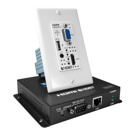
- Page 1 CHE-HDBTWP110K Pro AV/IT HDBaseT 4K60 18G Single Gang Wall Plate Extender Kit with HDMI, VGA, Audio up to 230ft Operation Manual...
- Page 2 SAFETY PRECAUTIONS Please read all instructions before attempting to unpack, install or operate this equipment and before connecting the power supply. Please keep the following in mind as you unpack and install this equipment: • Always follow basic safety precautions to reduce the risk of fire, electrical shock and injury to persons.
-
Page 3: Table Of Contents
CONTENTS 1. Introduction ........... 1 2. Applications ..........1 3. Package Contents ........2 4. System Requirements ........2 5. Features ............2 6. Operation Controls and Functions ....4 6.1 Front Panel ..........4 6.2 Rear Panel ..........5 6.3 WebGUI Control ........ -
Page 5: Introduction
1. INTRODUCTION The CHE-HDBTWP110K Wallplate Extender is an HDMI and VGA switch with audio embedding and HDBaseT output. The wallplate is designed for use with US single-gang sized enclosures. This Transmitter can send uncompressed high-definition video/audio over a single cable up to a distance of 100 meters at 1080p@60Hz. -
Page 6: Package Contents
3. PACKAGE CONTENTS • 1×HDMI/VGA over HDBaseT Transmitter • 1×2-pin Terminal Block • 1×US 1-Gang Faceplate • 1×HDMI over HDBaseT Receiver (PSE) • 1×48V/0.83A DC Power Adaptor • 1×Power Cord • 1×Operation Manual 4. SYSTEM REQUIREMENTS • HDMI or VGA source equipment such as a media player, video game console or set-top box. - Page 7 data over a single 100m/328ft Cat.5e/6/7 cable at 1080p60 and 70m/230ft at 4K • HDBaseT feature support: HD Video and Audio, 100BaseT Ethernet, 48V PoH, and Control (bidirectional IR/RS-232 pass-through) • Supports standard 48V PoH from Receiver (PSE) to Transmitter (PD) (compatible Transmitters only) Notes: •...
-
Page 8: Operation Controls And Functions
6. OPERATION CONTROLS AND FUNCTIONS 6.1 Front Panel FAC RESET Button: Press and hold for 5 seconds to reset the unit to its factory defaults. SERV.: This slot is reserved for firmware update use only. Note: This USB port can provide up to 500mA to connected devices. -
Page 9: Rear Panel
linked to a compatible Receiver. HDMI IN: Connect to HDMI source equipment such as a media player, game console or set-top box. 6.2 Rear Panel CAT5e/6/7 OUT: Connect to a compatible HDBaseT Receiver with a single Cat.5e/6/7 cable for transmission of all data signals. DC 12V: Connect a 12V DC power adapter to the twin terminal block and connect it to an AC wall outlet for power. - Page 10 LAN: Connect to an Ethernet device or to your local network as appropriate. POWER LED: This LED will illuminate to indicate the unit is on and receiving power. LINK LED: This LED will illuminate solid when both Transmitter and Receiver are connected and communicating with each other properly.
-
Page 11: Webgui Control
6.3 WebGUI Control • Device Discovery APP Please obtain the “Device Discovery” software from your authorized dealer and save it in a directory where you can easily find it. Connect the unit and your PC/Laptop to the same active network and execute the “Device Discovery”... - Page 12 • WebGUI Overview After connecting to the WebGUI’s address in a web browser, the login screen will appear. Please enter the appropriate user name and password then click “Submit” to log in. Note: The default user name and password is “admin”. On the left side of the browser you will see the following menu tabs where all primary functions of the unit (Switch, Automation, EDID Settings and System Settings) are controllable via the built in WebGUI.
-
Page 13: Switch Tab
6.3.1 Switch Tab This tab provides video/audio routing control as well as control over HDCP behavior, freerun settings, and naming of the Inputs and Output. To assign a new video route, please click the Output button and then click on the button of the preferred Input port to route. As you select each button they will change their color to orange. - Page 14 ■ Audio Route: Control the audio used when the HDMI input is active. Selecting “Bypass” will use the HDMI signal’s normal audio. Selecting “External” will use the analog stereo audio. ■ Freerun Mode: Enable or disable the video freerun function. When this is enabled, the selected freerun color will be displayed on the screen if there is no live source on the selected input.
-
Page 15: Automation Tab
6.3.2 Automation Tab The Automation tab provides control over the unit’s automatic control command broadcast behavior when the specified system Automation Events occur. Automation commands may be sent to 3rd party devices via standard CEC, or customizable RS-232. Note: Sending RS-232 commands requires the use of a compatible HDBaseT Receiver with an RS-232 port. - Page 16 ■ Wait: Set the length of time, in seconds, to wait after this CEC Automation Event has been activated before ANY other Automation Event can be detected. ■ CEC Command: Set the CEC command to send when the specified Automation Event is activated. Clicking the “Test” button will send the command immediately.
-
Page 18: Edid Settings Tab
6.3.3 EDID Settings Tab This tab provides control over the EDID behavior of the unit. There are six internal EDIDs, two customer uploaded EDIDs, and one sink sourced EDID that can be assigned to each input port individually. The sink EDID and both Customer EDIDs are also available for download to the connected PC. - Page 19 ■ All: Selecting this will allow the assignment of a single EDID to all Inputs simultaneously. ■ Appoint: Selecting this allows for a different EDID to be assigned to each Input. 4) Set EDID Input Content: This section provides a way to set the EDID to use with the selected Input.
-
Page 20: System Settings Tab
6.3.4 System Settings Tab This tab provides access to control a number of system configuration controls including displaying the unit’s serial number, modifying the web access privileges, changing the IP configuration, performing a factory reset, rebooting the system, and updating the firmware. 1) Serial Number: Displays the unit’s serial number. -
Page 21: Rs-232 Control
the firmware update file (*.bin format) located on your local PC. After selecting the file, click the “Upgrade” button to begin the firmware update process. Once the process completes the unit will automatically reboot. 6.4 RS-232 Control Unit Controlling PC Serial Port Settings Definition Definition... -
Page 22: Telnet Control
6.5 Telnet Control Before attempting to use Telnet control, please ensure that both the unit and the PC are connected to the same active networks. To Access the Command Line Interface (CLI) Windows 7 Click Start, type “cmd” in the search field, and press Enter. -
Page 23: Rs-232 And Telnet Commands
6.6 RS-232 and Telnet Commands COMMAND Description and Parameters HELP Show all available commands. ? Show all available commands. GET FW VER Show the unit’s firmware version. GET MODEL NAME Show the unit’s model name. GET MODEL TYPE ... - Page 24 COMMAND Description and Parameters GET IPCONFIG Show the current IP address details. SET IPADDR N1 Set the static IP Address. N1 = X.X.X.X [X = 0 ~ 255] GET IPADDR Show the current IP address. SET NETMASK N1 ...
- Page 25 COMMAND Description and Parameters GET OUT A NAME Show the output’s current name. SET OUT A ROUTE N1 Switch the output routing source to input N1. N1 = 1 ~ 2 [Input number] GET OUT A ROUTE Show the output’s current routing source.
- Page 26 COMMAND Description and Parameters GET IN PORT NUMBER Show the number of inputs on the unit. GET OUT PORT NUMBER Show the number of outputs on the unit. GET IN N1 SYNC STATUS Show the current sync status of input N1. N1 = 1 ~ 2 [Input number] Available Responses:...
- Page 27 COMMAND Description and Parameters SET ALL IN EDID N1 Set the EDID to use when set to “All mode”. Available values for N1: [8-bit/1080p/2CH LPCM] [8-bit/1080p/MCH] [12-bit/4K@30/2CH LPCM] [12-bit/4K@30/MCH] [12-bit/4K@60/2CH LPCM] [12-bit/4K@60/MCH] [User 1] [User 2] [Sink A] GET ALL IN EDID ...
- Page 28 COMMAND Description and Parameters GET IN EDID LIST List all available EDID sources. SET EDID N1 NAME N2 Set the name of User EDID N1 to N2. N1 = 7 ~ 8 [EDID number] N2 = {Name} [16 characters max] Note: Only User EDIDs can be renamed.
- Page 29 COMMAND Description and Parameters SET FREERUN A MODE N1 Enable or disable the freerun feature when there is no detected input. Available values for N1: [Freerun enabled] [Freerun disabled] GET FREERUN A MODE Show the current state of the freerun function. SET FREERUN A TYPE N1...
- Page 30 COMMAND Description and Parameters SET AUTOMATION EVENT N1 UART N2 Enable or disable the specified Automation Event's RS-232 response. Available values for N1: [Power on] [Out A source active] [Out A source lost] Available values for N2: [Event enabled] [Event disabled] GET AUTOMATION EVENT N1 UART...
- Page 31 COMMAND Description and Parameters GET AUTOMATION EVENT N1 UART DELAY Show the delay time for the specified Automation Event's RS-232 response. Available values for N1: [Power on] [Out A source active] [Out A source lost] SET AUTOMATION EVENT N1 UART WAIT N2 SEC ...
- Page 32 COMMAND Description and Parameters SET AUTOMATION EVENT N1 UART COMMAND N2 Set the RS-232 command string to send when the specified Automation Event is activated. Available values for N1: [Power on] [Out A source active] [Out A source lost] N2 = {Command} [Max 32 characters] GET AUTOMATION EVENT N1 UART COMMAND...
- Page 33 COMMAND Description and Parameters GET AUTOMATION EVENT N1 CEC Show the current state of the specified Automation Event's CEC response. Available values for N1: [Power on] [Out A source active] [Out A source lost] SET AUTOMATION EVENT N1 CEC DELAY N2 SEC ...
- Page 34 COMMAND Description and Parameters SET AUTOMATION EVENT N1 CEC WAIT N2 SEC Set the length of time to wait after an Automation Event's CEC response has been activated before ANY other Automation Event can be detected. Available values for N1: [Power on] [Out A source active] [Out A source lost]...
- Page 35 COMMAND Description and Parameters GET AUTOMATION EVENT N1 CEC COMMAND Show the CEC command to be sent when the specified Automation Event is activated. Available values for N1: [Power on] [Out A source active] [Out A source lost] SET UART 1 MODE N1 ...
- Page 36 COMMAND Description and Parameters SET UART 1 STOP BIT N1 Set the number of RS-232 stop bits to use. N1 = 1 ~ 2 GET UART 1 STOP BIT Show the current RS-232 stop bits setting. SET UART 1 DATA BIT N1 ...
-
Page 37: Connection Diagram
7. CONNECTION DIAGRAM Media Player HDMI Stereo Input Input Input Cat.5e/6/7 Cable FA C RE SE T VG A SERV. HD CP HDMI IN FO . HDMI RS-232 Equipped Output PC/Laptop Power Supply UHDTV... -
Page 38: Specifications
8. SPECIFICATIONS 8.1 Technical Specifications (Transmitter) HDMI Bandwidth 600MHz/18Gbps HDBaseT Bandwidth 340MHz/10.2Gbps Input Ports 1×HDMI 1×VGA (HD-15) 1×Stereo (3.5mm) Output Port 1×HDBaseT (RJ45) Baud Rate Up to 115200bps Power Supply 48V PoH or 12V/3A DC (US/EU standards, CE/FCC/UL certified) ESD Protection Human Body Model: ±12kV (Air Discharge) ±8kV (Contact Discharge) - Page 39 Input Port 1×Cat.5e/6/7 Output Port 1×HDMI Pass-through Ports 1×RS-232 [9-pin D-sub] 1×LAN [RJ45] Supported Resolutions 480i@60Hz - 4K@60Hz (4:2:0, 8-bit) VGA@60Hz - WUXGA@60Hz (RB) HDMI Cable Length 10m (1080p@60Hz, 12-bit) 5m (4K@60Hz, 4:4:4, 8-bit) CAT5e/6 Cable Length 100m (1080p@60Hz, 12-bit) 70m (4K@60Hz, 4:2:0, 8-bit) IR Frequency 30 - 50kHz (30 - 60kHz under ideal...
-
Page 40: Video Specifications
8.3 Video Specifications HDMI HDBaseT Supported PC Resolution (Hz) Input Input Output 640×480@60/72/75/85 720×400@70 800×600@56/60/72/75/85 1024×768@60/70/75/85 1152×864@75 1280×768@60/60 (RB) 1280×800@60/60 (RB)/75 ... -
Page 41: Audio Specifications
HDMI HDBaseT Input Input Supported TV Resolution (Hz) Output 3840×2160p@50/60 4096×2160p@50/60 8.4 Audio Specifications Analog Input Max Audio Level 2Vrms Impedance 10kΩ Type Unbalanced 8.5 Cable Specifications 1080p HDMI Cable Length 8-bit 12-bit 8-bit Input Output Cat. -
Page 42: Hdbaset Features
8.5 HDBaseT Features HDBaseT Feature Supported Video & Audio IR Pass-through RS-232 Pass-through Accept power from Receiver Send power to Receiver LAN Pass-through ... -
Page 43: Acronyms
9. ACRONYMS ACRONYM COMPLETE TERM Cat.5e Category 5 (enhanced) cable Cat.6 Category 6 cable Cat.7 Category 7 cable Consumer Electronics Control Digital Visual Interface High-Definition HDCP High-bandwidth Digital Content Protection HDMI High-Definition Multimedia Interface High Dynamic Range HDTV High-Definition Television Light-Emitting Diode LPCM Linear Pulse-Code Modulation...
Need help?
Do you have a question about the CHE-HDBTWP110K and is the answer not in the manual?
Questions and answers