
Related Manuals for Comprehensive CHE-HDBTWP100K


Summary of Contents for Comprehensive CHE-HDBTWP100K
- Page 1 CHE-HDBTWP100K Pro AV/IT HDBaseT 4K60 18G Single Gang HDMI Wall Plate Extender Kit up to 230ft Operation Manual...
-
Page 2: Table Of Contents
Thank you for purchasing this product For optimal performance and safety, please read these instructions carefully before connecting, operating or adjusting this product. Please keep this manual for future reference. Surge protection device recommended This product contains sensitive electrical components that may be damaged by electrical spikes, surges, electric shook, lighting strikes, etc. -
Page 3: Introduction
1. Introduction The HDBaseT Wall-plate Transmitter can transmit up to 4K2K@60 (4:4:4) video over a single CAT6/6a/7 cable up to 130ft/40m or 1080p up to 230ft/70m. It supports Power over Cable (PoC) functionality that allows for greater flexibility in installations. It also supports two-way IR and RS-232. -
Page 4: Package Contents
3. Package Contents 1× 18G HDMI Wall Plate Transmitter 1× Wideband IR blaster cable 1× Wideband IR receiver cable 1× Phoenix connector (3-pin) 1× Phoenix connector (2-pin) 1× User Manual 1× HDMI 18Gbps HDBaseT™ Receiver 1× 24V/1A DC Power Adaptor 4. - Page 5 Optical Audio Formats LPCM 2CH, LPCM 5.1, Dolby Digital 2/5.1CH, DTS 2/5.1CH ESD Protection Human body model—±8kV (Air-gap discharge) &±4kV (Contact discharge) Connections Transmitter Inputs: 1x HDMI Type A [19-pin female] 1x IR INPUT [Phoenix jack] 1x RS-232 [Phoenix jack] Outputs: 1x HDBaseT Out [RJ45] 1x IR OUTPUT [Phoenix jack]...
-
Page 6: Operation Controls And Functions
5. Operation Controls and Functions 5.1 Wallplate Front panel Number Name Function description HDMI IN Connect to HDMI source devices such as Blu-ray or PS4 player. ACTIVE Green LED input signal indicator. -
Page 7: Rear Panel
5.2 Wallplate Rear panel Number Name Function description HDBaseT OUT HDBaseT output port. Connect HDBaseT receiver with a UTP cable. 5V OUT Supply 5V power for external IR emitter. IR IN/OUT Use the phoenix jack for connect IR input or output. -
Page 8: Ir Port Connection Method
IR Connections The product supports IR control. If you need to use IR function of the product, you have to use the IR blaster cable and the IR receiver cable to phoenix connectors. Please see the following instructions : Step 1: For the IR Receiver, use a cutting tool to cut out the 3.5mm connector and split out the cable to three color wires –... - Page 9 Step 3: The wired IR cables should look as the follows - See Picture 3 [Picture 3] Step 4: Below is the pin-out diagram for the IR Blaster and Receiver - See Picture 4 [Picture 4]...
- Page 10 Step 5: Plug in both the IR Blaster and IR Receiver to the Phoenix jack. - See Picture 5 [Picture 5]...
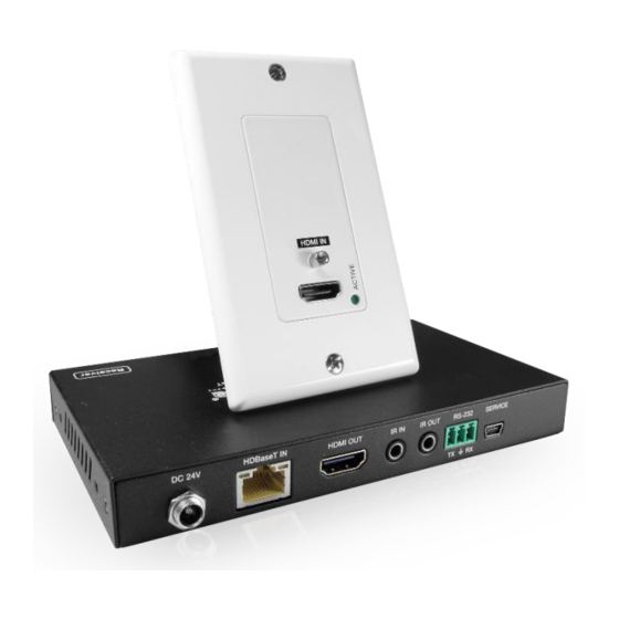
- Page 11 5.4 Receiver panel Power LED: System power indicator. DC 24V: Connect 24V/1A adaptor to AC wall outlet for power supply. HD BaseT In: Standard HD BaseT signal input port. Connect HD BaseT with a UTP cable following the standard of direct Transmitter interconnection method HDMI Out: HDMI output port.
- Page 12 ※Illuminate: The Transmitter and Receiver are in good connections status. ※Flashing: The Transmitter and Receiver are in poor connections status. ※Dark: The Transmitter and Receiver are not connected. Data Signal Indicator Lamp ※Illuminate: The HDMI signal with HDCP. ※Flashing: The HDMI signal without HDCP. ※Dark: No HDMI signal.
- Page 13 Application Diagram (B) - Bidirectional Infrared control Example Application Diagram (C) - Bidirectional RS-232 control Example...
-
Page 14: Application Example
7. Application Example 80 Little Falls Rd, Fairfield, NJ 07004 Phone: 1-800-526-0242 www.comprehensiveco.com sales@comprehensiveco.com...
Need help?
Do you have a question about the CHE-HDBTWP100K and is the answer not in the manual?
Questions and answers