Table of Contents

Related Manuals for ITech IT8600 Series


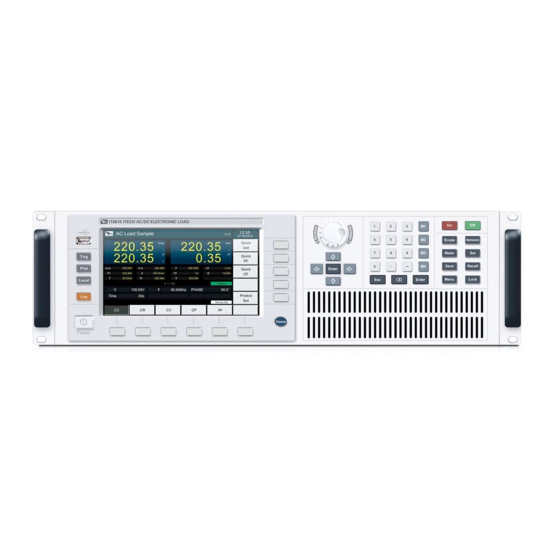
Summary of Contents for ITech IT8600 Series
- Page 1 ООО "Техэнком" Контрольно-измерительные приборы и оборудование www.tehencom.com Programmable AC/DC Electronic Load User Manual for IT8600 Series Model: IT8615/IT8615L/IT8616/IT8617/ IT8624/IT8625/IT8626/IT8627/IT8628 Version: V2.7...
- Page 2 Контрольно-измерительные приборы и оборудование www.tehencom.com Notices Warranty Safety Notices © Itech Electronic, Co., Ltd. 2019 The materials contained in this No part of this manual may be document are provided “as is”, and reproduced in any form or by any means...
-
Page 3: Warranty
We certify that IT8600 electronic load meets all the published specifications. Warranty ITECH warrants that the product will be free from defects in material and workmanship under normal use for a period of one (1) year from the date of delivery (except those described in the Limitation of Warranty below). - Page 4 Failure to comply with these precautions or specific warnings elsewhere in this manual will constitute a default under safety standards of design, manufacture and intended use of the instrument. ITECH assumes no liability for the customer’s failure to comply with these precautions.
-
Page 5: Environmental Conditions
European Legal Directives. The instrument complies with the WEEE Directive (2002/96/EC) marking requirement. This affixed product label indicates that you must not discard the electrical/electronic product in domestic household waste. Copyright © ITECH Electronic Co., Ltd. -
Page 6: Waste Electrical And Electronic Equipment (Weee) Directive
With reference to the equipment classifications described in the Annex I of the WEEE Directive, this instrument is classified as a “Monitoring and Control Instrument” product. To return this unwanted instrument, contact your nearest ITECH office. Copyright © ITECH Electronic Co., Ltd. -
Page 7: Compliance Information
Connection of the instrument to a test object may produce radiations beyond the specified limit. Use high-performance shielded interface cable to ensure conformity with the EMC standards listed above. Safety Standard IEC 61010-1:2010/ EN 61010-1:2010 Copyright © ITECH Electronic Co., Ltd. -
Page 8: Table Of Contents
4.3.2 Constant Resistance Mode (CR) ....................57 4.3.3 Constant Voltage Mode (CV) (Only for IT8615/IT8615L) ............57 4.3.4 Constant Power Mode (CP) ......................57 4.3.5 Short Circuit Simulation Function ....................57 Chapter5 Measurement Functions ....................59 Copyright © ITECH Electronic Co., Ltd. - Page 9 7.2 Setting of Harmonic Measurement Configuration ................72 Chapter8 Routine Maintenance ...................... 74 8.1 Error Information Reference ......................74 8.2 Routine Maintenance ......................... 75 8.3 Contact ITECH Engineer ........................76 8.4 Return for Repair ..........................77 Chapter9 Communication Interfaces ..................... 79 9.1 USB Interface ............................ 79 9.2 GPIB Interface ...........................
-
Page 10: Chapter1 Inspection And Installation
IT8616 and IT8617 have two sizes, including side plate structure and 15U cabinet. Besides, the 15U cabinet of IT8617 also has two types: one consists of one master and two slaves and the other consists of three masters. You can choose according to your requirement. Copyright © ITECH Electronic Co., Ltd. - Page 11 ООО "Техэнком" Контрольно-измерительные приборы и оборудование www.tehencom.com IT8615/IT8615L Dimension : Width: 482.50mm Height: 151.35mm Depth: 600.60mm Detailed Dimension Drawing IT8616 (side plate structure) Dimension : Width: 483.00mm Height: 348.99mm Depth: 641.08mm Copyright © ITECH Electronic Co., Ltd.
- Page 12 ООО "Техэнком" Контрольно-измерительные приборы и оборудование www.tehencom.com Detailed Dimension Drawing IT8616 (15U cabinet) Dimension: Width: 550.00mm Height: 801.40mm Depth: 839.10mm Copyright © ITECH Electronic Co., Ltd.
- Page 13 ООО "Техэнком" Контрольно-измерительные приборы и оборудование www.tehencom.com Detailed Dimension Drawing IT8617 (side plate structure) Dimension: Width:483.00mm Height:482.34mm Depth:641.08mm Detailed Dimension Drawing Copyright © ITECH Electronic Co., Ltd.
- Page 14 ООО "Техэнком" Контрольно-измерительные приборы и оборудование www.tehencom.com IT8617 (15U cabinet: one master and two slaves) Dimension: Width: 550.00mm Height: 801.40mm Depth: 839.10mm Detailed Dimension Drawing Copyright © ITECH Electronic Co., Ltd.
- Page 15 ООО "Техэнком" Контрольно-измерительные приборы и оборудование www.tehencom.com IT8617 (15U cabinet: three masters) Dimension: Width: 550.00mm Height: 801.40mm Depth: 839.10mm Detailed Dimension Drawing Copyright © ITECH Electronic Co., Ltd.
- Page 16 ООО "Техэнком" Контрольно-измерительные приборы и оборудование www.tehencom.com IT8624/IT8625/IT8626 Dimension: Width: 600.00mm Height: 1441.51mm Depth: 841.10mm Detailed Dimension Drawing Copyright © ITECH Electronic Co., Ltd.
- Page 17 ООО "Техэнком" Контрольно-измерительные приборы и оборудование www.tehencom.com IT8627/IT8628 Dimension: Width: 600.00mm Height: 1886.06mm Depth: 841.10mm Detailed Dimension Drawing Copyright © ITECH Electronic Co., Ltd.
-
Page 18: Connecting The Power Cord
China America, Canada, Europe Britain Japan IT-E171 IT-E173 IT-E174 IT-E172 ⚫ The power cord of IT8616(15U cabinet)/IT8617(15U cabinet)/IT8624 /IT8625/IT8626/IT8627/IT8628 electronic load is shown in the next figure. Copyright © ITECH Electronic Co., Ltd. - Page 19 Connect the brown terminal to line (L), blue to neutral (N), and yellow-green to ground. 2. Connect the plug on the other end of the power cord to your AC power source. Copyright © ITECH Electronic Co., Ltd.
-
Page 20: Connecting Test Lines
1. Respectively connect drive wires to six terminals Vs+/ V+/ V+ and Vs-/ V-/V- of the rear panel. 2. Respectively connect the other ends of wires to the anode and cathode of the test object (as shown below). Copyright © ITECH Electronic Co., Ltd. - Page 21 ⚫ The wiring for basic measurements of Model IT8616(15U cabinet)/IT8617 (15U cabinet: one master and two slaves)/IT8624/IT8625/IT8626/IT8627 /IT8628 is as follows. Copyright © ITECH Electronic Co., Ltd.
-
Page 22: Chapter2 Quick Start
LCD (Liquid Crystal Display) functions of IT8600 series loads to help the user know the appearance, structure and key functions before operation and better operate these loads. -
Page 23: Front Panel Introduction
13 Esc key and Enter key 7 Memory key 2.3 Key Introduction The key functions of the front panel and the keys in the key zones of IT8600 are shown in the following figure. Copyright © ITECH Electronic Co., Ltd. - Page 24 Used to delete the input digits in the digit editing mode. Used for enabling the load function and input. Used for disabling the load function and input. Setting key used for setting loading parameters. Meter Basic metering key used for basic metering. Copyright © ITECH Electronic Co., Ltd.
-
Page 25: Introduction To Information On The Interface
The interface of IT8600 electronic load will display the following symbols. All the symbols and description are listed in the table below. Symbol Description Symbol Description SHORT Enable the short-circuit Record log. function. Remote function. CF-PRIO CF Priority. Copyright © ITECH Electronic Co., Ltd. -
Page 26: Rear Panel Introduction
3: Current monitor terminal 8: USB communication interface 4: Voltage monitor terminal 9: LAN communication interface 5: System bus: for master/slave power input socket control system data (support 100V-240V input voltage, communication including fuse) Copyright © ITECH Electronic Co., Ltd. - Page 27 The figure below shows the rear panel. 1. Communication interface threading hole 2. Load input terminals 3. Remote measurement terminals 4. Power master switch 5. AC power input terminals Copyright © ITECH Electronic Co., Ltd.
- Page 28 These terminals are the same as those of IT8615. 1. Communication interface and test line threading hole 2. Power master switch 3. AC power cord threading hole Copyright © ITECH Electronic Co., Ltd.
-
Page 29: Power-On Self-Test
Before operation, please confirm that you have fully understood the safety instructions. Introduction of Switch You can turn on the instrument by switch. Descriptions of the switch are as follows: Copyright © ITECH Electronic Co., Ltd. - Page 30 The LCD screen displays the electronic load version and time information. After initialization, the LCD screen displays the following information. NOTE In case of any error, self-test will stop. Contact ITECH sales agent or technical service engineer. Press [Menu], and the LCD screen of the electronic load displays the system information.
- Page 31 LED display, etc. Input Inspection 50Vrms. The minimum AC input voltage of IT8600 AC/DC electronic load is 10Vrms. The minimum DC input voltage of IT8600 AC/DC electronic load is Copyright © ITECH Electronic Co., Ltd.
- Page 32 2. Have a visual inspection of the fuse to see whether it is burnt out; if yes, replace it with another fuse of the same specification. Refer to the corresponding technical specifications for fuse rating. 3. After replacement, mount the fuse block to the original position, as illustrated below: Copyright © ITECH Electronic Co., Ltd.
-
Page 33: Chapter3 Basic Operations
(Disable/ Enable), only for the load with DC mode Harmonic formula: THDF/ THDR Harmonic Formula Peak holding mode: Off/ On Peak Hold Mode Power-on status: SAV0/RST ⚫ Power On Setting If Rst is selected, factory settings are recovered after each start-up Copyright © ITECH Electronic Co., Ltd. - Page 34 Total Slave Unit Total Slave Unit Only valid when the operating mode is set to Parallel Parallel setup (IT8620 PARALLEL SETUP Series) Operating Mode: Single/ Parallel ⚫ Operating Mode Single: single mode ⚫ Parallel: parallel mode Copyright © ITECH Electronic Co., Ltd.
-
Page 35: Configuration Save/Recall
2. Press [Save] to save the data. Set “Save file to:”. Set the FILE number to be saved at present as 3. Press [Enter] to confirm the file number. 3. Press [Enter] to save. Copyright © ITECH Electronic Co., Ltd. -
Page 36: Screen Capture Function
AC load operating mode by pressing the soft keys corresponding to CC, CR and CP in the setting interface. When the DC load is simulated, you can press [Set] on the front panel, and then select the DC load operating mode by Copyright © ITECH Electronic Co., Ltd. -
Page 37: Data Recording Function
When the loading time reaches the set time, the input will be turned off automatically. The user can enable the timing mode in the system setting menu, as shown below. 1. Press [Menu] to enter the system setting interface. Copyright © ITECH Electronic Co., Ltd. -
Page 38: Protection Function
Setting of protection function The OCP (Current Rms Protect), OCPP (Current Peak Protect) and OPP (Power Protect) functions of IT8600 AC/DC load can be set. 1. Press [Set]. Copyright © ITECH Electronic Co., Ltd. - Page 39 If the current of the test object is beyond the rated current range or the protection current range, disconnect the test object, and press any key on the front panel (or send the Copyright © ITECH Electronic Co., Ltd.
- Page 40 Loading failure occurs in the following cases: ⚫ The input voltage is 0 during loading; ⚫ The voltage is reduced to 0 during loading; ⚫ The load hardware is abnormal; ⚫ The voltage and loading current fluctuates continuously. Copyright © ITECH Electronic Co., Ltd.
-
Page 41: Remote Measurement Function
NOTE In order to ensure the stability of the system, using armored twisted pair cable between the remote sense terminals and DUT. The schematic diagram of remote sense measurement is shown as follow. Copyright © ITECH Electronic Co., Ltd. -
Page 42: External On/Off Control
IT8600 programmable AC/DC load can be used in parallel connection of multiple units of the same models to test power supplies of high power. In parallel application, AC and DC operations can be carried out in the CC/CR/CP mode. Copyright © ITECH Electronic Co., Ltd. - Page 43 1. Press [Menu] to enter the system menu setting interface. 2. Select [PARALLEL SETUP] to enter the parallel setting interface. 3. Press the Up and Down key to select the “Operating Mode” > “Parallel”. 4. Set “Master/Slave” as Slave, as shown below: Copyright © ITECH Electronic Co., Ltd.
- Page 44 5. Set “Total Slave Unit” as 1, as shown below: 6. Press [Enter] to save the setting. After saving the settings, the user must power off two electronic loads and power on again. The interfaces of master and slave are shown as below. Copyright © ITECH Electronic Co., Ltd.
- Page 45 2. Select [PARALLEL SETUP] to enter the parallel setting interface. 3. Press the Up and Down key to select the “Operating Mode” > “Parallel”. 4. Set “Phase Class” as “Single”. 5. Set “Phase/Position” of each unit as “Slave-B(2)” and “Slave-C(3)”. Copyright © ITECH Electronic Co., Ltd.
- Page 46 6. Set “Total Unit” as 3. 7. Press [Enter] to save the setting. After saving the settings, the user must power off three electronic loads and power on again. The interfaces of master and slave are shown as below. Copyright © ITECH Electronic Co., Ltd.
-
Page 47: Three-Phase Function
Take the example of IT8615 electronic load, the schematic diagram of three-phase connection is as follows. When you connect system bus, the Terminating Resistor is a must for the first load unit and the last load unit. Copyright © ITECH Electronic Co., Ltd. - Page 48 1. Press [Menu] to enter the system menu setting interface. 2. Select [PARALLEL SETUP] to enter the parallel setting interface. 3. Press the Up and Down key to select the “Operating Mode” > “Parallel”. Copyright © ITECH Electronic Co., Ltd.
- Page 49 6. Set “Total Slave Unit” as 2, as shown below: 7. Press [Enter] to save the setting. After saving the settings, the user must power off the three electronic loads and power on again. Copyright © ITECH Electronic Co., Ltd.
- Page 50 The interface of master is shown as below. ⚫ Take the example of IT8628 electronic load Select two electronic loads as the slaves. 1. Press [Menu] to enter the system menu setting interface. Copyright © ITECH Electronic Co., Ltd.
- Page 51 2. Select [PARALLEL SETUP] to enter the parallel setting interface. 3. Press the Up and Down key to select the “Operating Mode” > “Parallel”. 4. Set “Phase Class” as “A+B+C”. 5. Set “Phase/Position” as “Master-A(1)”. 6. Set “Total Unit” as 3. Copyright © ITECH Electronic Co., Ltd.
-
Page 52: Three-Phase Parallel Function
Connections of three-phase parallel power supplies include Y-type and Δ-type connection, as shown in the following figures. When you connect system bus, the Terminating Resistor is a must for the first load unit and the last load unit. ⚫ Y-type connection Copyright © ITECH Electronic Co., Ltd. - Page 53 2. Select [PARALLEL SETUP] to enter the parallel setting interface. 3. Press the Up and Down key to select the “Operating Mode” > “Parallel”. 4. Press the Up and Down key to select the “Single/Three Phase” > “Single”. 5. Set “Master/Slave” as Master. Copyright © ITECH Electronic Co., Ltd.
-
Page 54: Three-Phase Setup
3.20 Three-phase setup You can set different power or current in three-phase mode. Press [Enter] to save the parameter of three-phase, then press [Set] to enter into the configure interface, as shown as below. Copyright © ITECH Electronic Co., Ltd. - Page 55 ⚫ YES: Balance mode. You can set value of each phase consistently. Set Sel Select A/B/C/ABC phase. You can set ABC phase only in balance mode. View Sel Select the phase A/B/C to display. Copyright © ITECH Electronic Co., Ltd.
-
Page 56: Chapter4 Load Functions
⚫ Constant current mode (CC); ⚫ Constant resistance mode (CR); ⚫ Constant power mode (CP). 4.2.1 CF and PF Setting The operating modes of the AC load mode include the constant current mode, Copyright © ITECH Electronic Co., Ltd. -
Page 57: Constant Current Mode (Cc)
For details of undervoltage protection, refer to 3.12 Protection Function. The voltage-current relation is shown below: load Set current current Load input voltage CC mode Fig. 3-1 Voltage-current Relation in CC Mode Copyright © ITECH Electronic Co., Ltd. - Page 58 2. Press the Up and Down key to select the parameter to be set. 3. Directly set the present value through the knob or press numeric keys to input the value. In case of wrong input by numeric keys, press delete the present input. Copyright © ITECH Electronic Co., Ltd.
- Page 59 2. Press the Up and Down key to select the parameter to be set. 3. Directly set the present value through the knob or press numeric keys to input the value. In case of wrong input by numeric keys, press delete the present input. Copyright © ITECH Electronic Co., Ltd.
- Page 60 2. Press the Up and Down key to select the parameter to be set. 3. Directly set the present value through the knob or press numeric keys to input the value. In case of wrong input by numeric keys, press delete the present input. Copyright © ITECH Electronic Co., Ltd.
-
Page 61: Constant Resistance Mode (Cr)
Operating steps 1. Press [Set] and [CR] to enter the parameter setting interface of CR Mode. Rset=2500Ω The resistance, input voltage and load’s sink current should meet the requirements of R=U/I. Copyright © ITECH Electronic Co., Ltd. -
Page 62: Constant Power Mode (Cp)
3. Press the Up and Down key to select the parameter to be set. 4. Directly set the present value through the knob or press numeric keys to input the value. In case of wrong input by numeric keys, press delete the present input. Copyright © ITECH Electronic Co., Ltd. - Page 63 3. Press the Up and Down key to select the parameter to be set. 4. Directly set the present value through the knob or press numeric keys to input the value. In case of wrong input by numeric keys, press delete the present input. Copyright © ITECH Electronic Co., Ltd.
- Page 64 3. Press the Up and Down key to select the parameter to be set. 4. Directly set the present value through the knob or press numeric keys to input the value. In case of wrong input by numeric keys, press delete the present input. Copyright © ITECH Electronic Co., Ltd.
-
Page 65: Dc Load Function
In this mode, the electronic load will sink a constant current in accordance with the programmed value regardless of the input voltage. See figure 3-4. Load Set current Current Load input voltage CC mode Figure 3-4 CC mode Copyright © ITECH Electronic Co., Ltd. -
Page 66: Constant Resistance Mode (Cr)
The electronic load can simulate a short circuit at the input end in the DC load mode. You can press [Short] to switch over the short circuit status. Short circuit operations have no influence on the present setting. When the OFF status is Copyright © ITECH Electronic Co., Ltd. - Page 67 Press the Up and Down key and select “Short Function”. Press the soft key corresponding to [On] on the right side to enable the short circuit simulation function. 3. Press [START] and [STOP] to start and stop short circuit simulation. Copyright © ITECH Electronic Co., Ltd.
-
Page 68: Chapter5 Measurement Functions
The measured value displayed in large letters on the upper part of the interface can be modified according to the user requirements. Press [CONFIG] to enter the metering parameter configuration interface. Press the soft key corresponding to the metering parameter. Copyright © ITECH Electronic Co., Ltd. -
Page 69: Ac Mode
CC, CR and CP Mode. CC Mode Press [Set] to enter the default CC Mode. Set the current value and start loading in CC Mode. The metering interface and parameters are shown in the following figure. Copyright © ITECH Electronic Co., Ltd. - Page 70 CR Mode. The metering interface and parameters are shown in the following figure. CP Mode Press [Set] and [CP] to enter CP Mode. Set the resistance value and start loading in CP Mode. The metering interface and parameters are shown in the following figure. Copyright © ITECH Electronic Co., Ltd.
-
Page 71: Dc Mode
CC Mode. The metering interface and parameters are shown in the following figure. CR Mode Press [Set] to enter the default CR Mode. Set the resistance and start loading in CR Mode. The metering interface and parameters are shown in the following figure. Copyright © ITECH Electronic Co., Ltd. - Page 72 CV Mode (Only for IT8615/IT8615L) Press [Set] to enter the default CV Mode. Set the resistance and start loading in CV Mode. The metering interface and parameters are shown in the following figure. Copyright © ITECH Electronic Co., Ltd.
- Page 73 ООО "Техэнком" Контрольно-измерительные приборы и оборудование www.tehencom.com Measurement Functions Copyright © ITECH Electronic Co., Ltd.
-
Page 74: Chapter6 Waveform Display Function
⚫ Volt Range ⚫ CURR Range ⚫ Volt Base ⚫ Curr Base ⚫ Trig Level ⚫ Trig Delay ⚫ Time/div RUN/STOP Run/stop: press the corresponding soft key to run or stop the waveform status. Copyright © ITECH Electronic Co., Ltd. - Page 75 Trigger Description State The selected trigger mode is “Auto”. After triggering, the trigger Auto state “Auto” appears. The selected trigger mode is “Auto”. The trigger state is “Auto?” Auto? if triggering is not performed. Copyright © ITECH Electronic Co., Ltd.
- Page 76 ⚫ Trigger source The trigger source is used for generating trigger conditions. The user can select the trigger source in the input signal of the input unit. Copyright © ITECH Electronic Co., Ltd.
-
Page 77: Adjustment Of Measurement Parameters
3. Rotate the knob to adjust the parameter. Corresponding value changes will be displayed in the interface. 6.3 Setting of Trigger Configuration To enable the trigger function, you should select the trigger source, trigger mode, trigger slope, etc. Detailed steps are as follows. Copyright © ITECH Electronic Co., Ltd. - Page 78 Source (trigger source): select the voltage or current as the trigger source. Mode (trigger mode): select the Auto or Normal mode. Slope (trigger slope): select the rising edge, falling edge or rising/falling. Copyright © ITECH Electronic Co., Ltd.
-
Page 79: Chapter7 Harmonic Measurement Function
% r: displaying harmonics in the form of percentage to the overall voltage amplitude of all harmonics. % f: displaying harmonics in the form of percentage to the fundamental voltage. CHART Bar chart form. LIST List form. Copyright © ITECH Electronic Co., Ltd. - Page 80 ⚫ Harmonic list When “LIST” is selected in the harmonic measurement mode, the list of harmonic measurement results will be displayed, including the voltage, phase and voltage harmonic distortion factor (UTHD) of each harmonic. Copyright © ITECH Electronic Co., Ltd.
-
Page 81: Setting Of Harmonic Measurement Configuration
) to the maximum harmonic order (within the upper limit of analysis orders) as the denominator. ⚫ %f: using the data of fundamental wave (1-order) components as the denominator. The distortion factor calculation formulas and methods of different measurement functions are as follows: Copyright © ITECH Electronic Co., Ltd. - Page 82 Total harmonics are calculated as follows: Total Total . k indicates the harmonic order, and max indicates the upper limit of Total analysis orders. max is determined by the frequency of PLL source automatically, 50 orders at most. Copyright © ITECH Electronic Co., Ltd.
-
Page 83: Chapter8 Routine Maintenance
Save4 is performed Save3 is performed Save2 is performed Save1 is performed Recall4 is performed Recall3 is performed Recall2 is performed Recall1 is performed Save screen ok Log stop Log start Copyright © ITECH Electronic Co., Ltd. -
Page 84: Routine Maintenance
2. Press [>>] to display the system menu in the scrolling form. 3. Press the soft key corresponding to [SYSTEM INITIAL] to enter the system initialization interface, as shown below. 4. Press the Up and Down key and select the menu item (blue background) to Copyright © ITECH Electronic Co., Ltd. -
Page 85: Contact Itech Engineer
SN collection ITECH will improve the product performance, availability and reliability from time to time. The service personnel of ITECH will record the changes of each instrument, and all the relevant information will be identified according to the SN. The SN will be used as the tracking ID of the instrument returned for repair. -
Page 86: Return For Repair
In this interface above, “Serial” is the instrument SN. 3. Record the SN. Calibration interval The calibration frequency recommended by ITECH for IT8600 AC/DC load is once a year. 8.4 Return for Repair Before returning the instrument for repair, please read the following requirements. - Page 87 Контрольно-измерительные приборы и оборудование www.tehencom.com Routine Maintenance generated by styrene particles or penetration of styrene particles into holes of the rear panel. Read the requirements of transportation costs of warranty services in the foreword before delivery. Copyright © ITECH Electronic Co., Ltd.
-
Page 88: Chapter9 Communication Interfaces
Select LAN by pressing up/down keys and then configure Gateway, IP, Mask and Socket Port in the LAN options. Use a cross network cable through LAN interface to connect PC. Copyright © ITECH Electronic Co., Ltd. -
Page 89: Chapter10 Technical Specifications
DC Section Input voltage 10V-600V Input parameter Input current 0.1A-20A Input power 0-1800VA Operating Mode CC, CV, CR and CP Short Circuit The maximum power or current in CC mode Simulation Meter Current Range 0-60A Copyright © ITECH Electronic Co., Ltd. - Page 90 *3. Operating temperature: 0-40℃ , temperature coefficient: 100ppm/℃ Parameter IT8615L V1.1 AC Section Input voltage 15~260Vrms , 360V peak Current 0~20Arms ,60Apeak Input parameter Power 0~1800VA Frequency 45~450Hz Range 0.1~20Arms CC mode Resolution Accuracy ± (0.1%+0.2%FS) 3Ω~2.5KΩ CR mode Range Copyright © ITECH Electronic Co., Ltd.
- Page 91 Simulation Meter Range 0~60A Current Resolution Accuracy 0.1%+0.2%FS+0.1%*CF^2*KHZ Range 0~360V Voltage Resolution 10mV Accuracy 0.1%+0.1%FS Meter (continue) Other Parameters S(VA),Q(VAR),P(W),Ip+,Ip-,Freq,THDv,CF,PF,R,FFT Other V monitor ±360v/±10V(Isolation) I monitor ±60A/± 10V(Isolation) Protection OCP:21Arms,OVP:286Vrms,OPP:1900W,OTP:85℃ Interface GPIB, USB, LAN Copyright © ITECH Electronic Co., Ltd.
- Page 92 Resolution 0.4W Accuracy 0.5%+0.5%FS Range 1.414~5.0 Crest Factor(CF) (in CP and CC Resolution 0.005 mode) Accuracy (1% / Irms) + 1% FS Range 0~1 lead or lag Power Factor (PF) Resolution 0.001 DC Section Copyright © ITECH Electronic Co., Ltd.
- Page 93 Test condition: The voltage/current input is no less than 10% FS *3. Operating temperature: 0-40℃ , temperature coefficient: 100ppm/℃ Parameter IT8617 (AC/DC Load) V1.3 AC Section Input voltage 50~420Vrms, 600V peak Parameter Input current 0~60Arms, 180A peak Copyright © ITECH Electronic Co., Ltd.
- Page 94 Delta or Star connection type are supported of IT8617.The connection depends on user’s testing requirement. AC Section Input voltage 50~420Vrms, 600V peak Input current 0~20Arms, 60A peak Parameter Input power 0-1800VA Frequency 45~450Hz Copyright © ITECH Electronic Co., Ltd.
- Page 95 0.2% +0.02S 7.2kW Range CP mode Resolution 0.5%+0.5%FS Accuracy 1.414~5.0 Range Crest Factor(CF) 0.005 Resolution (CP,CC mode) (2% / Irms) + 1% FS Accuracy Range 0~1 lead or lag Power Factor (PF) 0.001 Resolution Copyright © ITECH Electronic Co., Ltd.
- Page 96 *1, Typical parameter values in case of the 45-100HZ *2, The scope of read-back resistance is( 1/(1/R+(1/R)*0.2%+0.01),1/(1/R-(1/R)*0.2%-0.01) Test condition: The voltage/current input is no less than 10% FS. Parameter IT8625 V1.3 AC Section Copyright © ITECH Electronic Co., Ltd.
- Page 97 Input power Operating CC, CR, CP Mode Short Circuit The max. power point or max. current in CC mode Simulation Meter 0-300A Range Current Resolution 0.1A 0.1%+0.2%FS+0.1%*CF^2*KHZ Accuracy Range 0-600V 10mV Voltage Resolution 0.1%+0.1%FS Accuracy Copyright © ITECH Electronic Co., Ltd.
- Page 98 0-10.8kW 45~450Hz Frequency Range 0.1~120Arms 20mA CC mode *1 Resolution ± (0.5%+0.5%FS) Accuracy 0.5Ω~416.6Ω Range 16bit CR mode *2 Resolution Accuracy 0.2% +0.02S 10.8kW Range CP mode Resolution 0.5%+0.5%FS Accuracy 1.414~5.0 Crest Factor(CF) Range Copyright © ITECH Electronic Co., Ltd.
- Page 99 600.00mm(W) * 1475.01mm(H) *841.1mm(D) Weight 185KG Voltage 100-240V AC Frequency 47-63 Hz AC Input Working <9A(110V), <4.5A(220V) current *1, Typical parameter values in case of the 45-100HZ *2, The scope of read-back resistance is( 1/(1/R+(1/R)*0.2%+0.01),1/(1/R-(1/R)*0.2%-0.01) Copyright © ITECH Electronic Co., Ltd.
- Page 100 Input current 0-12.6kW Input power Operating CC, CR, CP Mode Short Circuit The max. power point or max. current in CC mode Simulation Meter 0-420A Range Current Resolution 0.1A 0.1%+0.2%FS+0.1%*CF^2*KHZ Accuracy Voltage Range 0-600V Copyright © ITECH Electronic Co., Ltd.
- Page 101 Input current Parameter 0-14.4kW Input power 45~450Hz Frequency Range 0.8~160Arms 20mA CC mode *1 Resolution Accuracy ± (0.5%+0.5%FS) 0.375Ω~312.5Ω Range CR mode *2 Resolution 16bit 0.2% +0.02S Accuracy 14.4kW Range CP mode Resolution 0.5%+0.5%FS Accuracy Copyright © ITECH Electronic Co., Ltd.
- Page 102 S(VA),Q(VAR),P(W),Ip+,Ip-,Freq,THDv,CF,PF,R,FFT Parameters Other ±600v/±10V(Isolation) Voltage Monitor ±480A/±10V(Isolation) Current Monitor Protection OCP:≈185rms,OVP:≈430Vrms,OPP:≈14.6kW,OTP:85℃ GPIB, USB, LAN Interface Dimension 600.00mm(W) * 1919.40(H) *841.1mm(D) Weight 214KG Voltage 100-240V AC Frequency 47-63 Hz AC Input Working <12A(110V), <6A(220V) current Copyright © ITECH Electronic Co., Ltd.
-
Page 103: Supplemental Characteristics
*1, Typical parameter values in case of the 45-100HZ *2, The scope of read-back resistance is( 1/(1/R+(1/R)*0.2%+0.01),1/(1/R-(1/R)*0.2%-0.01) Test condition: The voltage/current input is no less than 10% FS. 10.2 Supplemental characteristics ⚫ Recommended calibration frequency Once a year ⚫ Cooling style Fans Copyright © ITECH Electronic Co., Ltd. -
Page 104: Appendix
Specifications of Red and Black Test Lines ITECH provides you with optional red and black test lines, which individual sales and you can select for test. For specifications of ITECH test lines and maximum current values, refer to the table below. - Page 105 Контрольно-измерительные приборы и оборудование www.tehencom.com Contact US Thank you for purchasing ITECH products. If you have any doubt about this product, please contact us as follows. 1. Please refer to the CD-ROM of related user’s manual in package. 2. Visit ITECH website www.itechate.com .
Need help?
Do you have a question about the IT8600 Series and is the answer not in the manual?
Questions and answers