
Subscribe to Our Youtube Channel
Related Manuals for ITech IT7800 Series


Summary of Contents for ITech IT7800 Series
- Page 1 Programmable AC Power Supply IT7800 Series User Manual Model: IT7800 Version: V1.0/2021.04...
- Page 2 Notices Warranty Safety Notices © Itech Electronic, Co., Ltd. 2021 The materials contained in this No part of this manual may be document are provided “as is”, and reproduced in any form or by any is subject to change, without prior means ( including electronic storage notice, in future editions.
-
Page 3: Warranty
IT7800 User Manual Quality Certification and Assurance We certify that IT7800 series power supply meets all the published specifications at time of shipment from the factory. Warranty ITECH warrants that the product will be free from defects in material and workmanship under normal use for a period of one ( 1) year from the date of delivery ( except those described in the Limitation of Warranty below). - Page 4 Failure to comply with these precautions or specific warnings elsewhere in this manual will constitute a default under safety standards of design, manufacture and intended use of the instrument. ITECH assumes no liability for the customer’s failure to comply with these precautions.
-
Page 5: Environmental Conditions
( if any) affixed refers to the year when the design was approved. The instrument complies with the WEEE Directive 2002/96/EC) marking requirement. This affix product label indicates that you must not discard the electrical/electronic product in domestic household waste. Copyright ©ITECH Electronic Co., Ltd. -
Page 6: Waste Electrical And Electronic Equipment ( Weee) Directive
With reference to the equipment classifications described in the Annex 1 of the WEEE Directive, this instrument is classified as a “Monitoring and Control Instrument”. To return this unwanted instrument, contact your nearest ITECH office. Copyright ©ITECH Electronic Co., Ltd. -
Page 7: Compliance Information
2. Connection of the instrument to a test object may produce radiations beyond the specified limit. 3. Use high-performance shielded interface cable to ensure conformity with the EMC standards listed above. Safety Standard IEC 61010-1:2010/ EN 61010-1:2010 Copyright ©ITECH Electronic Co., Ltd. -
Page 8: Table Of Contents
5.1.4 View the System Information ........................45 5.2 Configuration Menu Reference .......................... 46 5.3 Key Lock Function ............................... 48 5.4 Switching Local/Remote Mode .......................... 48 5.5 Save and Recall Operations ..........................49 5.6 Protection Function ............................50 Copyright ©ITECH Electronic Co., Ltd. - Page 9 9.4 GPIB Interface (Optional) ........................... 96 9.5 RS-232 Interface (Optional) ..........................97 9.6 Commonly Used Commands Overview ......................98 9.7 Demo Software Introduction ..........................99 APPENDIX................................100 ........................ 100 PECIFICATIONS OF ED AND LACK INES Copyright ©ITECH Electronic Co., Ltd.
-
Page 10: Chapter1 Quick Reference
Chapter1 Quick Reference This chapter introduces the front panel, the rear panel, key functions and LCD display function of the IT7800 series power supply, make sure that you can quickly know the appearance, instruction and the key function before you operate the power supply. -
Page 11: Front Panel Introduction
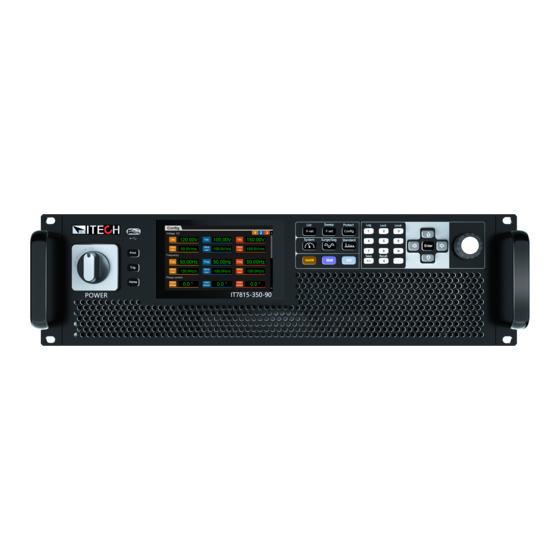
Take IT7815-350-90 for an example, the rated power is 15kVA, rated voltage is 350V and rated current is 90A. 1.2 Front Panel Introduction The front panel of IT7800 is as shown below. Copyright ©ITECH Electronic Co., Ltd. -
Page 12: Keyboard Introduction
5 Number key 6 Up, down, left and right key and enter key 7 Rotary knob 8 Vent hole 1.3 Keyboard Introduction The keyboard introduction of IT7800 series Power Supply is shown as follows. Keys Description Print Used for saving screen images... - Page 13 When you need to keep the present meter status, you can press the keys. Then the present meter status display and will be kept no matter whether output is running. [Shift]+ [7] (Help) Obtain the help information. Copyright ©ITECH Electronic Co., Ltd.
-
Page 14: Push-On Knob
Quick Reference 1.4 Push-on Knob The IT7800 series Power Supply provides a knob on the front panel as shown in the next figure. The functions of the posh-on knob is described as follows. ⚫ Adjust the value setting Select menu item ⚫... -
Page 15: Home-Screen Overview
Used to connect AC power to start instrument. socket 1.6 Home-Screen Overview IT7800 series power supply adopts touch screen design, the users can easily operation by touch screen. The power supply can work in either single-phase mode or three-phase mode. - Page 16 Quick Reference Single Phase Mode The meter interface of IT7800 series power supply is shown as follow. Status bar Voltage setting&meter value Frequency setting&meter value Display area of measuring data Three Phase Mode The meter interface of IT7800 three phase mode is shown as follow.
- Page 17 The AC source is in Surge&Sag function remote mode indicator External Simulation Test Record log Function LIST is running LIST is finished LIST function is waiting for Sweep function is trigger waiting for trigger Copyright ©ITECH Electronic Co., Ltd.
-
Page 18: Optional Accessories
The IT7800 series supports the following optional accessories (sold separately), the details are as below: The interface expansion slot provided on the rear panel of the IT7800 series instrument allows users to flexibly expand according to their needs. Different interface cards can be selected to achieve different functions. - Page 19 2.5m fiber cable. The fiber optic module and cable are the necessary accessories for the parallel connection. Different numbers of fiber optic modules and cables are used in different numbers of parallels. Copyright ©ITECH Electronic Co., Ltd.
-
Page 20: Chapter2 Inspection And Installation
2.2 Instrument Size Introduction The instrument should be installed at well-ventilated and rational-sized space. Please select appropriate space for installation based on the power supply size. IT7815-350-90 model Copyright ©ITECH Electronic Co., Ltd. -
Page 21: Connectiong The Power Cord
Safety agency requirements dictate that there must be a way to physically disconnect the AC mains cable from the unit. A disconnect device, either a Copyright ©ITECH Electronic Co., Ltd. - Page 22 Take the 3kVA instrument for example, the rated AC current of each phase for the single unit is L1/L2:18A, L3:0A, and can support single phase AC input. different model of rated AC current is different, the detailed specification refer to the technical specification. Copyright ©ITECH Electronic Co., Ltd.
- Page 23 It is recommended to follow the suggestion connection diagram as below. Single phase input connecting: Three phase input connecting: When connecting the instrument which rated power is 6kVA or above ⚫ The AC input is three phase and balanced, connecting the power cord as below. Copyright ©ITECH Electronic Co., Ltd.
-
Page 24: Connecting Test Lines ( Optional)
⚫ Always use test lines provided by ITECH to connect the equipment. If test lines from other factories are used, please check that the test line can withstand maximum current. - Page 25 The connection diagram of three phase is shown as follow: ⚫ The connection diagram of split phase is shown as follow: NOTE When the output voltage has DC voltage, the output terminal A is positive, and B is negative. Copyright ©ITECH Electronic Co., Ltd.
- Page 26 To maximize measurement accuracy, the power system provides the remote measurement terminals VS+ and VS- on the rear panel, which can be used to measure the terminal voltage of the DUT. When the power system is used for battery testing in actual applications, the Copyright ©ITECH Electronic Co., Ltd.
- Page 27 The connection diagram of single phase is shown as follow: NOTE When the output voltage has DC voltage, the output terminal L is positive, and N is negative. The connection diagram of three phase is shown as follow: ⚫ Copyright ©ITECH Electronic Co., Ltd.
- Page 28 7. Connect the other end of the red and black cables to the DUT. The positive and negative poles must be properly connected and fastened when wiring. 8. Power on the instrument and turn on the Sense function of the instrument. Copyright ©ITECH Electronic Co., Ltd.
-
Page 29: Chapter3 Getting Started
The disconnect device must be close to the equipment, be easily accessible, and be marked as the disconnect device for this equipment. Copyright ©ITECH Electronic Co., Ltd. -
Page 30: Touch Screen Introduction
Getting Started Power Switch Introduction The POWER switch knob of the IT7800 series power supply is on the left side of the front panel. The user can turn ON the power by 90° clockwise. Turning the POWER Switch On Check that the power cord is connected properly. -
Page 31: Output On/Off Control
The VFD displays the meter value such as voltage, current, power and so on. If the [On/Off] key light is off, indicates that the output is turned off. The VFD displays that the power supply state is OFF. Copyright ©ITECH Electronic Co., Ltd. -
Page 32: Chapter4 Operation And Application
Under the Multi-channel phase, the power supply works as a single phase power supply and have three channels. The multi-channel function of the IT7800 series allows users to test 3 independent DUTs at the same time without adding additional hardware configuration. -
Page 33: Select The Output Mode
Operation and Application 4.2 Select the Output Mode The IT7800 series has four output modes: AC, DC, AC+DC, DC+AC. It not only provides pure AC/DC output, but also can use AC+DC and DC+AC output modes to realize "AC output plus DC bias" And "DC output waveform with ripple", which cover a wider range of applications. -
Page 34: Ac+Dc Mode
DC power supply. If there are strict noise requirements, additional DC noise filters are needed to obtain low noise and good stable DC voltage for testing. Copyright ©ITECH Electronic Co., Ltd. -
Page 35: Dc+Ac Mode
The Vac setting range is 10% of rated voltage. 4.3 Waveform Selection The user can set the output waveform in the config menu of IT7800 series power supply. Eight output waveforms below are available, user can select the waveform in Config->Waveform menu. -
Page 36: Auto-Range Function
4.4 Auto-range Function IT7800 series power supply can achieve the combined output of multiple voltage and current at a fixed power. Single power supply can meet different DUT tests with high voltage low current or high current low voltage, at the same time, because the output of voltage and current is controlled by the limit power, it will show the switching of voltage and current auto ranging. -
Page 37: Current Limit Mode And Power Limit Mode
30V or more is required for 100% current output. 4.6 Current Limit Mode and Power Limit Mode The IT7800 series power supply defaults to constant voltage CV output mode. The output voltage can be set in main interface. - Page 38 • off: Directly off the output after the execution is finished; • Last: Keep the last waveform unchanged after the execution is finished. Normal: return to normal mode after the sweep execution is finished. Copyright ©ITECH Electronic Co., Ltd.
-
Page 39: Power Amplifier
Sweep function. 4.8 Power Amplifier The IT7800 series regenerative grid simulator can be used as a power amplifier to complete power hardware in the loop (PHIL) applications for microgrids, energy storage and new energy vehicles. The digital I/O or a standard suite of analog signal can be input via an external analog interface (optional) and then amplified without distortion to a real power waveshape. -
Page 40: Polyphase Function
Operation and Application 4.10 Polyphase Function IT7800 series power supply to achieve 6 phase& 12 phase power output through digital IO interface. Taking the 6 phase power supply as an example, introduces the application method of polyphase function. Connecting the IO-4 pin Connect the IO-4 pins of two IT7800 power supplies. - Page 41 Angle difference between the first power supply and the input signal power supply is set to 60°, the Angle difference between the second power supply and the input signal power supply is set to 120°, and so on. Copyright ©ITECH Electronic Co., Ltd.
-
Page 42: Chapter5 System-Related Functions
I/O input signal. Set the frequency difference upper Freq limit- limit between the output frequency and the external I/O input signal. Set the output mode when the Exception frequency lock fails: ⚫ Stop: stop output Copyright ©ITECH Electronic Co., Ltd. - Page 43 Set the instruments to parallel operation mode. Parallel mode ⚫ Master: Set the instrument to master mode. Single: Set the instrument to single Parallel mode, i.e., disable the parallel ⚫ operation mode. ⚫ Slave: Set the instrument to slave mode. Copyright ©ITECH Electronic Co., Ltd.
- Page 44 Addr Set the instrument address to a number Select RS-232 communication interface. When insert RS232 config IT-E177 communication board into expansion slot, the menu displays this information. Baud rate Baud rate Databits Data bit: 5/6/7/8 Copyright ©ITECH Electronic Co., Ltd.
- Page 45 ON/OFF TRIG2 ⚫ ⚫ Input ⚫ Output INPUT ⚫ ⚫ OUTPUT Product model Display the instrument model. Serial number Display the serial number. Information Software version Display the control board version. MAC address MAC address Copyright ©ITECH Electronic Co., Ltd.
-
Page 46: Menu Function
2. Press the Up/Down key or turn the knob to select the Touch screen lock and press [Enter]. ⚫ On: enable the touch screen ⚫ Off: disable the touch screen Set the Loop Speed This item can control stability of the loop. When the connected load is capacitive Copyright ©ITECH Electronic Co., Ltd. -
Page 47: Set The Communication Interface
5.1.2 Set the communication interface This menu item is used to set the communication information between instrument and PC. The standard communication interfaces for IT7800 series power supply are USB, LAN and CAN. You can also select the non-standard interface GPIB or RS-232 based on personal requirement. -
Page 48: Configuration Menu Reference
Output voltage Vac: output voltage of AC, range from 0-full Voltage AC scale Slew Rate: Slope , range from 0.001- 5000V/ms Freq: output frequency, range from 16- 2400Hz Frequency Slew Rate: slope, range from 0.001- 5000Hz/ms Copyright ©ITECH Electronic Co., Ltd. - Page 49 AB and AC. Dimming Function The front and back edge of the waveform can by concealed and the phase angle set with Dimmer function to regulate the active power, thus adjusting the lighting intensity. Copyright ©ITECH Electronic Co., Ltd.
-
Page 50: Key Lock Function
You can press the [Shift] +[3] (Local) button to change the AC source from remote to local operation. After you power on the AC source, it defaults in local mode, all buttons are enabled. While in remote mode, most buttons are disabled except [Shift] +[3] Copyright ©ITECH Electronic Co., Ltd. -
Page 51: Save And Recall Operations
You can recall the parameters you saved in the specified memory location as the setting values. Press the composite keys [Shift]+[5] (Recall) to enter the parameter recallinterface. Set the storage location. Press the direction keys to set the storage location, and then, the saved Copyright ©ITECH Electronic Co., Ltd. -
Page 52: Protection Function
Press [Enter] to recall the parameters. 5.6 Protection Function IT7800 series source includes the following protection functions: overcurrent protection (Current RMS protection, Current peak protection), voltage limit protection and over-temperature protection (OTP). -
Page 53: Current Rms Protection
Press the up/down key or rotate the knob to select Current peak protection and press [Enter]. Set the protection peak Level and the delay time in sequence, and press [Enter] to confirm. Clear Peak OCP Protection When peak OCP protection occurs, the instrument responds as follows: Copyright ©ITECH Electronic Co., Ltd. -
Page 54: Set Voltage/Current/Power Limit Range
OPP mode. 5.7 Screen Capture Function IT7800 series power supply has the screen capture function. Insert the USB equipment into the USB interface of the front panel, and press [Print] on the front panel to capture and save the current screen into the USB disk. -
Page 55: Trigger Function
Interface terminal on the rear panel, the power supply will be triggered once. 5.9 Set Parallel Operation Mode The IT7800 series power supply supports multiple instruments to work in parallel mode to provide more power and current output capability. Under the parallel mode, All features are set up from the master unit. - Page 56 2. Set three units in parallel mode with one master and two slaves. 3. Press the composite keys [Shift]+ (System) on the front panel to enter the system menu. 4. Select General menu. Copyright ©ITECH Electronic Co., Ltd.
-
Page 57: Remote Measurement Function
After the instrument is restarted, the screen shows that the instrument is working in single mode. 5.10 Remote Measurement Function The IT7800 series power supply supports two connection methods: Local measurement and Remote sensing. The remote sensing is used for maximizing measurement accuracy. (Refer to 2.4 Connecting Test Lines). -
Page 58: Digital I/O Function
IT7900, the output signal is the level signal provided externally by IT7900, and the pulse signal is the edge signal switched between high and low levels. Typical: 5V Input signal High level signal Range: 1.6V-15V Current: ≤100mA Copyright ©ITECH Electronic Co., Ltd. - Page 59 OFF. If power supply output is ON state before, the ON/OFF button will be lit. When the input signal undoes, the output returns to normal. This function can be used to control the output of the power supply. Copyright ©ITECH Electronic Co., Ltd.
- Page 60 IO-6 can be set to【Trigger1-in】, 【Trigger1-out】, 【Input】,【Output】 【Trigger1-in】: The input trigger signal, the pulse signal sent to the IO-6 pin can be used as the trigger source. Users can select as the trigger source of the Copyright ©ITECH Electronic Co., Ltd.
-
Page 61: Analogue Function (Ext-Program) (Optional)
5.12 Analogue Function (Ext-Program) (Optional) The interface expansion slot provided on the rear panel of the IT7800 series. This function is not standard with the instrument and is optional for users. When the interface card selected by the user is RS232+Analog interface (IT- E177), the analog interface can realize the external analog function. - Page 62 When the voltage setting is controlled through the analog interface, the external voltage (-10V ~ 10V) is connected to program the voltage value between 0 and full scale(AC mode). Copyright ©ITECH Electronic Co., Ltd.
- Page 63 The -10V ~ 10V voltage reading corresponds to the power voltage and current output between negative full range and positive full scale (For AC, 0 to 10V corresponds to 0 to full scale). The wiring diagram is shown in the figure below. Copyright ©ITECH Electronic Co., Ltd.
- Page 64 System-Related Functions Copyright ©ITECH Electronic Co., Ltd.
-
Page 65: Chapter6 Measurement Functions
This chapter describes the characteristics and operations of the basic metering function of IT7800 series source. IT7800 series source has rich functions of basic metering of electric energy and can accurately measure the parameters such as Vrms, Irms, Ipeak, Idc, CF, PF. -
Page 66: Oscilloscope Mode
DC current 6.2 Oscilloscope Mode IT7800 series source has the function of displaying the waveform based on sampling data. The user can select to display or hide the voltage and current waveform of the input unit. Only the necessary waveform is displayed, which can facilitate observation. - Page 67 In the Normal mode, the displayed waveform will be updated in the case of Copyright ©ITECH Electronic Co., Ltd.
-
Page 68: Harmonic Measurement
⚫ Both: Post and Raw, record two data file. 6.3 Harmonic measurement IT7800 series source can display harmonic parameters in the list or bar chart form to make the analysis of test result clear. Press key on the front panel, and the following initial interface of harmonic measurement will appear. - Page 69 Phase A, and displays 0 for the other two phases, as shown in the figure below; under three-phase mode, display effective values for the three phases. Copyright ©ITECH Electronic Co., Ltd.
-
Page 70: Recorder Function
The data recording function allows you to observe and record output status data for a long time. On the recorder interface, you can select a maximum of six data curves to be displayed.See the figure below. Copyright ©ITECH Electronic Co., Ltd. - Page 71 Hold-On/Hold-Off: Pause screen data refresh (for data observation)/ Start dynamically observing the data Auto: Automatically adjusts the scale of the appropriate vertical axis. Time: The time value of each of the horizontal coordinates, unit is s/Div Vernier: Position information of the vernier caliper. Copyright ©ITECH Electronic Co., Ltd.
-
Page 72: Chapter7 Configuration Arbitrary Waveform
Press [Shift]+[V-set](list) on the front panel to enter the List function configuration interface, as shown in the figure below. 888.csv: the list file name to execute. Trig source: select the trigger source Run/Stop: Run/stop the list function. Open: Select the List file to execute. Copyright ©ITECH Electronic Co., Ltd. - Page 73 Save: Save the list file. Config: configure the list file to make it effective. Clear all: delete all of step information Trig source: select trigger source Click (More)… enter to advanced menu of list file. Copyright ©ITECH Electronic Co., Ltd.
-
Page 74: Select/Run List File
If several List files are edited, press Recall to recall the List file to be tested. Detailed operation steps are as below: Press [Shift]+[V-set](list) on the front panel to enter the List function configuration interface. Press [Open], select the saved List01.csv file, and press [Enter] to enter Copyright ©ITECH Electronic Co., Ltd. -
Page 75: Import/Export List File
7.1.3 Import/Export List file Import List file IT7800 series support import list file function, The user can finish the editing of List file in Excel and import it into the software. This function simplifies the List file edit and facilitates user operation. -
Page 76: Setting Of Surge/Sag Configuration
Action This setting is valid when the mode select to Trigger. Imme: Executing the surge/sag immediately Angle: Executing the surge/sag at specific angle. Trig source Select the trigger source when the mode select to Trigger. Copyright ©ITECH Electronic Co., Ltd. -
Page 77: Self-Defined Waveform Function
List operation. The new waveform file, after saving, will be added after the original waveform file. The user can self-define five waveform files at maximum. 7.3.1 THD The distorted waveform can simulate voltage harmonic wave in the circuit. The Copyright ©ITECH Electronic Co., Ltd. - Page 78 User THD wave: THD wave of user defined. “+” Create a new THD wave. “-“ Delete the seleted THD wave. “ ” Edit the THD wave. Press the “+” or “ ” enter to the edit interface. Thd profile: THD file name Copyright ©ITECH Electronic Co., Ltd.
-
Page 79: User-Defined Waveform
Back: return back upper menu. THD=: Total distortion rate calculated based on the user Thd configuration. 7.3.2 User-defined waveform “+” create a new wave. “-” delete the wave file. “ ” edit the wave file. Edit interface: Copyright ©ITECH Electronic Co., Ltd. - Page 80 Origin Symmetry: To select the waveform data type, you can select 512 origin symm/512 origin asymm /1024 points Open: import waveform data. Save: Save the user-define wave. Delete: select a row and click Delete. Clean: delete all of data Back: return back upper menu. Copyright ©ITECH Electronic Co., Ltd.
-
Page 81: Chapter8 Technical Specifications
16~500 Range High 16~2.4k Resolution 0.01 0.01% 16Hz~500Hz Accuracy 0.1% 500.01Hz~ 2.4kHz waveform 50/60Hz up to 50 order synthesizer Phase Range ° 0~360 Resolution ° Voltage setting Range 1phase -495~495 Resolution 0.01 <0.1%+0.1% F.S Accuracy Copyright ©ITECH Electronic Co., Ltd. - Page 82 <0.4% +0.4% F.S. DC,16~500Hz Accuracy <0.4% +(0.8%*kHz) F.S 500.01Hz~ 2.4kHz Harmonic Max. 50/60Hz up to 50 order measurement Others Efficiency Protection OVP, OCP, OPP, OTP, FAN, Sense Working 0℃- 50℃ Programming response time Remote Sense Compensation Copyright ©ITECH Electronic Co., Ltd.
-
Page 83: It7805-350-30U
The dynamic response time test condition is: DC high-speed mode, and the capacitance of the DUT to be less than 10uF All the above parameters are subject to change without prior notice from ITECH IT7805-350-30U Input parameters... -
Page 84: It7806-350-90
When loopSpeed Low is low,it can better complied DUT’s characteristics; When LoopSpeed is High,the dynamic response *5The dynamic response time test condition is: DC high-speed mode, and the capacitance of the DUT to be less than 10uF All the above parameters are subject to change without prior notice from ITECH. IT7806-350-90 Input parameters... - Page 85 -495~495 Range reverse -990~990 Resolution 0.01 <0.1%+0.1% F.S Accuracy Temperature < 100ppm/℃ F.S coefficient Current setting multichannel/reverse -30~30 Range DC Output 1phase -90~90 Resolution 0.01 <0.3%+0.3% F.S Accuracy Temperature < 200ppm/℃ F.S coefficient Max. power Copyright ©ITECH Electronic Co., Ltd.
- Page 86 The dynamic response time test condition is: DC high-speed mode, and the capacitance of the DUT to be less than 10uF All the above parameters are subject to change without prior notice from ITECH. Copyright ©ITECH Electronic Co., Ltd.
-
Page 87: It7809-350-90
Accuracy 0.1% 500.01Hz~2.4kHz waveform 50/60Hz up to 50 orders synthesizer Phase Range ° 0~360 Resolution ° Voltage setting 1phase/multichannel -495~495 Range reverse -990~990 Resolution 0.01 <0.1%+0.1% F.S Accuracy Temperature < 100ppm/℃ F.S coefficient Current setting Copyright ©ITECH Electronic Co., Ltd. - Page 88 The dynamic response time test condition is: DC high-speed mode, and the capacitance of the DUT to be less than 10uF All the above parameters are subject to change without prior notice from ITECH. Copyright ©ITECH Electronic Co., Ltd.
-
Page 89: It7812-350-90
0.01% 16Hz~500Hz Accuracy 0.1% 500.01Hz~2.4kHz waveform 50/60Hz up to 50 orders synthesizer Phase Range ° 0~360 Resolution ° Voltage setting 1phase/multichannel -495~495 Range reverse -990~990 Resolution 0.01 Accuracy <0.1%+0.1% F.S Temperature < 100ppm/℃ F.S coefficient Copyright ©ITECH Electronic Co., Ltd. - Page 90 (0.8%*kHz) F.S Harmonic Max. 50/60Hz up to orders measurement Others Efficiency Protection OVP, OCP, OPP, OTP, FAN,ECP,Sense Working 0℃-50℃ Programming response time Remote Sense Compensatio Voltage Communicatio Built-in USB/CAN/LAN/Digital IO interface, optional GPIB / Analog&RS232 interface Copyright ©ITECH Electronic Co., Ltd.
-
Page 91: It7815-350-90
The dynamic response time test condition is: DC high-speed mode, and the capacitance of the DUT to be less than 10uF All the above parameters are subject to change without prior notice from ITECH. IT7815-350-90 Input parameters... - Page 92 500.01Hz~2.4kHz Harmonic Max. 50/60 up to 50 orders measurement Others Efficiency Protection OVP, OCP, OPP, OTP, FAN,ECP,Sense Working 0℃-50℃ Programming response time Remote Sense Compensatio Voltage Communicatio Built-in USB/CAN/LAN/Digital IO interface, optional GPIB / Analog&RS232 Copyright ©ITECH Electronic Co., Ltd.
- Page 93 The dynamic response time test condition is: DC high-speed mode, and the capacitance of the DUT to be less than 10uF All the above parameters are subject to change without prior notice from ITECH. Copyright ©ITECH Electronic Co., Ltd.
-
Page 94: Supplemental Characteristics
When loopSpeed Low is low,it can better complied DUT’s characteristics; When LoopSpeed is High,the dynamic response time is faster. All the above parameters are subject to change without prior notice from ITECH. 8.2 Supplemental characteristics Recommended calibration frequency: once a year Cooling style: fans Copyright ©ITECH Electronic Co., Ltd. -
Page 95: Chapter9 Remote Control
4. Select the USB type to Device. 9.2 LAN Interface When the user connect PC through LAN interface, the following is required to use the LAN interface. The LAN interface complies with the LXI standard. Copyright ©ITECH Electronic Co., Ltd. - Page 96 When the instrument and computer are connected to the router, an independent IP address must be assigned for the instrument. Configure LAN Interface Information The configurable parameters of the IT7800 series power supply are described as follows. LAN Config: Mode: IP Address seting method, user can selectautomatically configure the ⚫...
-
Page 97: Can Interface
Select the baud rate from the following options: 5k/10k/20k/40k/50k/80k/100k/125k/200k/250k/400k /500k/600k/800k/1000k The operation steps are as follows. 1. Press the composite keys [Shift]+ (System) on the front panel to en- ter the system menu. 2. Select Communication and press [Enter]. Copyright ©ITECH Electronic Co., Ltd. -
Page 98: Gpib Interface (Optional)
Each device on the GPIB (IEEE-488) interface must have a unique whole num- ber address between 1 and 30. Your computer’s GPIB interface card address must not conflict with any instrument on the interface bus. This Copyright ©ITECH Electronic Co., Ltd. -
Page 99: Interface (Optional)
When using the RS-232 interface for communication, connect the pin 1, pin 2, and pin 3 of the IT-E177 to the PC. The pin description is as follows: Pins Description TXD, transmit data RXD, receive data Copyright ©ITECH Electronic Co., Ltd. -
Page 100: Commonly Used Commands Overview
COM2, etc) of PC. 9.6 Commonly Used Commands Overview The IT7800 series AC/DC power supply can be connected with the remote control device through the communication interface to realize the remote operation instrument by sending SCPI commands. This series of power supplies provides a detailed commands reference IT7800 Programming Guide. -
Page 101: Demo Software Introduction
//To clear the protection status -> OUTPut:PROTection:CLEar 9.7 Demo Software Introduction IT7800 series AC/DC power supply provides the following computer control software, convenient for users to achieve different test control.The standard version of the software can be downloaded from the official website, and the optional version of the software needs to be purchased separately. -
Page 102: Appendix
Appendix Specifications of Red and Black Test Lines ITECH provides you with optional red and black test lines, the user can choose the company's test line for testing. For specifications of ITECH test lines and maximum current values, refer to the table below. - Page 103 Contact US Thank you for purchasing ITECH products. If you have any doubt about this product, please contact us as follow. 1. Please refer to the user’s manual in website. www.itechate.com 2. Visit ITECH website...
Need help?
Do you have a question about the IT7800 Series and is the answer not in the manual?
Questions and answers