Table of Contents
Advertisement
Quick Links
P712 OWNER'S MANUAL CONTENTS
1. INTRODUCTION..................................................................................................
2. IMPORTANT SAFETY PRECAUTIONS...............................................................
3. LIST OF PARTS...................................................................................................
STEP 1 Cover Support Plate and the Connector Installation............................
STEP 2 Connector and the Seat Frame Installation..........................................
STEP 3 Weight Stack Installation......................................................................
STEP 4 CAM Installation...................................................................................
STEP 5 Cable Installation...................................................................................
STEP 6 Handle Installation................................................................................
STEP 7 Arm Cushion Installation.......................................................................
STEP 8 Seat Bottom Installation........................................................................
STEP 9 Apply the Weight Stack Sticker..............................................................
STEP 10 Front Cover and the Rear Cover Installation .......................................
STEP 11 Top Covers Installation...........................................................................
STEP 13 Cable Adjustment..................................................................................
STEP 14 Stack Fork Inspections..........................................................................
5. OPERATION INSTRUCTION.................................................................................
6. MAINTENANCE.....................................................................................................
Maintenance Machine Maintenance......................................................................
Maintenance Schedule..........................................................................................
Maintenance Task List...........................................................................................
Maintenance One-year Maintenance Log..............................................................
7. CONSIGNES DE SECURITE IMPORTANTES.....................................................
'
'
.......................................................................
1
2
3
8
12
13
17
20
23
24
25
26
27
28
29
30
31
32
33
33
34
35
36
37
Advertisement
Table of Contents

Related Manuals for SportsArt Fitness P712


Summary of Contents for SportsArt Fitness P712
-
Page 1: Table Of Contents
P712 OWNER’S MANUAL CONTENTS 1. INTRODUCTION....................2. IMPORTANT SAFETY PRECAUTIONS............... 3. LIST OF PARTS....................4. ASSEMBLING THE PRODUCT STEP 1 Cover Support Plate and the Connector Installation......STEP 2 Connector and the Seat Frame Installation.......... STEP 3 Weight Stack Installation.............. -
Page 2: Introduction
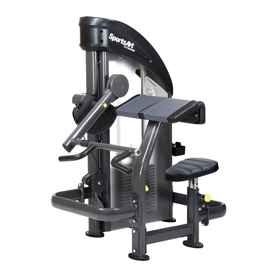
1. INTRODUCTION Congratulations on the purchase of a high quality SportsArt product, the P712 Biceps Curl machine. Constructed of high quality materials and designed for years of reliable performance, this product was made for full commercial use. Before this product is assembled or operated, we recommend that you familiarize yourself with this manual. -
Page 3: Important Safety Precautions
2. IMPORTANT SAFETY PRECAUTIONS This product was designed and built for optimum safety. However certain precautions apply during the use of this product. Please note the following safety precautions: .Please read the entire manual before assembly and operation. Make sure the product is installed and operated as instructed in this manual. -
Page 4: List Of Parts
3. LIST OF PARTS Box A... - Page 5 Box B Box C...
- Page 6 Box A - Main Frame Components Name Qty No. Description Weight stack top right cover Cover support plate A Weight stack top left cover Cover Main frame Pulley cover Cover support plate B-2 Pulley Rear cover Cover support plate B-1 Front cover Storage tray Bracket...
- Page 7 Components on the Product Specification Name Notes For∮50 Connector Hex head screw M10*P1.5*L130 Spring washer Washer D16*d10.2*t1.0 Nylon hex lock nut Hex head screw M10*P1.5*L30 Spring washer Washer D16*d10.2*t1.0 Nylon hex lock nut Hex head screw M10*P1.5*L75 Spring washer Washer D16*d10.2*t1.0 Connector C W60*L156*t5...
- Page 8 Components on the Product Specification Notes Name Mushroom top inner hex screw M8*P1.25*L25 Spring washer Mushroom top inner hex screw M8*P1.25*L25 Spring washer Bevelled head inner hex screw M8*P1.25*L20 Nylon hex lock nut Plastic round head inner hex screw M6*P1.0*20 Bushing ∮D21.5*10.5 Mushroom top inner hex screw...
-
Page 9: Assembling The Product
4. ASSEMBLE THE PRODUCT Follow instructions below to assemble this product. Note that in this manual the words “left” and “right” are used to refer to the product and its parts. As such, these designations correspond to the “left” and “right” sides of a person in position to exercise on this product. - Page 10 *Loosen and remove the screws (30) (31) (32) and the connecting plates from the components (A22) (A27) (A28) as shown. Carefully set each piece aside.
- Page 11 (a). Insert the screw sockets (10) into place in the main frame (A3) as shown and then use the screws (11) (12) to secure the brackets (A16) (A17) in place. (Note: The bracket (A16) must be secured to the top of maim frame as shown.)
- Page 12 (b). Use the screws (13) to secure the cover support plates (A10) to the straight frame of the main frame (A3) and then secure the cover support plates (A4) (A5) to the both side of the curved frame as shown. (Note: The cover support plates must be secured outside of the bracket (A16) (A17).)
-
Page 13: Step 2 Connector And The Seat Frame Installation
STEP 2 Connector and the Seat Frame Installation (a). Use the connector B (A28) to connect the main frame (A3) and secure the screws (30) as shown, and then use the screws (31) to secure the connector B (A28) into the place in the seat frame (A24) as shown. (b). -
Page 14: Step 3 Weight Stack Installation
STEP 3 Weight Stack Installation... - Page 15 (a). Hold the upper stack carriage set (33) and then cut the zip tie. Gently lower the upper stack carriage set (33) into place as shown. (b). Remove the screws (34) and then set the guide rod (35) downward into place as shown.
- Page 16 (d). Loosen and remove the screws (36) from the stack fork (A7) and insert the weight stack rod (A8) into the central mounting position of the upper stack carriage set (33). Use the screws (36) to secure the stack fork (A7) into place of the upper stack carriage set (33) as shown.
- Page 17 (f). Tilt the guide rods (35) back into place and lift them up to their mounting position, and then secure the assembly with the screws (34).
-
Page 18: Step 4 Cam Installation
STEP 4 CAM Installation... - Page 19 (a). Loosen and remove the screw (37) and the cap (38) from the CAM (A20) and the screws (39) from the CAM support plate (A26). (b). Use the screws (39) to secure the CAM support plate (A26) into the place in the CAM (A20) as shown.
- Page 20 (d). Screw the axle cover (38) in place with the screw (37) and then apply the round sticker (15) as shown. (Note: The stopper must be rested below the tube as shown.) (e). Loosen and remove the screws (40) from the CAM mounting area. (f).
-
Page 21: Step 5 Cable Installation
STEP 5 Cable Installation (a). Insert the cable nut as indicated by the arrows onto the weight stack rod (A8) at least 15-20mm deep as shown. (b). Take out the stack fork (A7) and lift the upper stack carriage set (33) up. (c). - Page 22 (a). Loosen and remove the screws (41) (43) (45), the cable set block (42) and the CAM stop plate (44) from the main frame. (b). Install the pulley (A13) and insert the cable goes through the pulley (A13) as indicated by the arrows, and then screw the pulley cover (A12) in place with the screw (41).
- Page 23 (d). After completing the cable installation, hold the upper stack carriage set (33), and then take out the stack fork (A7). Gently lower the upper stack carriage set (33). (Note: Please make sure that the cable is running in the grove of the pulley. Rotate the CAM to check for cable interference and its tightness.
-
Page 24: Step 6 Handle Installation
STEP 6 Handle Installation (a). Loosen and remove the screws (46) from the handle (A21). (b). Place the stem of the handle (A21) on the right and insert it into the handle mount onto the rotator. From the bottom side, secure the screws (46) on the handle. -
Page 25: Step 7 Arm Cushion Installation
STEP 7 Arm Cushion Installation (a). First, remove the screws (47) from the arm cushion (A23). (b). Set the arm cushion (A23) on the arm cushion frame (A22), and then align holes and secure the assembly with the screws (47). -
Page 26: Step 8 Seat Bottom Installation
STEP 8 Seat Bottom Installation (a). First, remove the screws (48) (49) from the seat bottom (A25) and the seat frame (A24). (b). Use the screws (49) to secure the seat bottom plate to the seat frame (A24) as shown. (c). -
Page 27: Step 9 Apply The Weight Stack Sticker
STEP 9 Apply the Weight Stack Sticker Note: Before applying the weight plate stickers, please wipe the area clean, and clean your hands before proceeding to the next step. (a). Align and tape the cardboard to the upper left corner of the weight plate (A30). (b). -
Page 28: Step 10 Front Cover And The Rear Cover Installation
STEP 10 Front Cover and the Rear Cover Installation (a). Use the screws (11) to secure the cover bracket (A9) in place on the main frame (A3) as shown. (b). Slide the front cover (A14) (A15) from the top down into the cover support plates' grooves. -
Page 29: Step 11 Top Covers Installation
STEP 11 Top Covers Installation * Secure the weight stack top right cover (A1) and the top left cover (A2) with the screws (14). (Note: During assembling, place the bracket of the top covers inside of the cover support plates (A4) (A5) as shown.) -
Page 30: Step 12 Storage Tray Installation
STEP 12 Storage Tray Installation (a). Loosen and remove the screws (51) (52) from the storage tray (A6) and the main frame. (b). Hold the storage tray (A6) in place and secure it with the bracket and the screws (51) (52) as shown. -
Page 31: Step 13 Cable Adjustment
STEP 13 Cable Adjustment * Insert the stack fork into the gap under the lowest weight plate, and then adjust the large nut at area C. Adjust until the upper stack carriage set moves slightly. To adjust the cable, first insert the (Z) rod and loosen the (Y) nut, and then adjust the (X) nut. -
Page 32: Step 14 Stack Fork Inspections
STEP 14 Stack Fork Inspections * Please follow operating instructions on the product sticker to test operation and confirm that the equipment is working properly. * Insert the stack fork to make sure that every weight plate can be engaged easily. * Insert the stack fork at the heaviest weight setting at which you can safely operate the equipment. -
Page 33: Operation Instruction
5. OPERATION INSTRUCTION Seat bottom height positioning can be adjusted. Simply, put out the related knob, make the adjustment, and release the knob to secure the desired position. -
Page 34: Maintenance
6. MAINTENANCE This section covers maintenance topics and includes a maintenance schedule, task list, and log. Maintenance Machine Maintenance 1. Apply lubricant to the guide rods every week. Procedure: (a). Put some lubricant on a clean, lint-free cloth. Rub the lubricated cloth on the guide rods. -
Page 35: Maintenance Schedule
Maintenance Schedule (P712) Maintenance Schedule Area Week Month Quarter Year Clean Exterior Inspect for looseness and Screws secure if necessary. Check for proper equipment Test operation. Seat bottom/ Use damped cloth to clean. Arm cushion Check for damage or wear. -
Page 36: Maintenance Task List
Maintenance Task List Like cars, fitness products require maintenance. Regular maintenance extends product life, and failure to maintain products can void the manufacturer's warranty. Copy the maintenance log sheet, and record maintenance work for each fitness product. Daily tasks 1. Use a clean, lint-free towel to wipe down the product exterior. 2. -
Page 37: Maintenance One-Year Maintenance Log
Maintenance One-Year Maintenance Log Facility : Supervisor: Product Model Number : Serial Number: Start Date: End Date: Daily Tasks Weeks 1-7 Weeks 8-14 Weeks 15-21 Weeks 22-28 Completed Daily Tasks Weeks 29-35 Weeks 36-42 Weeks 43-49 Weeks 50-52 Completed Weekly Tasks Weeks 1-7 Weeks 8-14 Weeks 15-21... -
Page 38: Consignes De Securite Importantes
‘ ‘ 7. CONSIGNES DE SECURITE IMPORTANTES Le produit SportsArt a été conçu et fabriqué afin d'assurer une sécurité optimale. Cependant certaines précautions s'appliquent chaque fois que vous utilisez votre produit. .Lisez entièrement le manuel avant l'assemblage et l'utilisation. Veuillez aussi noter les consignes de sécurité... - Page 39 ATTENTION Si vous ressentez une douleur ou si vous avez une sensation anormale, ARRÊTEZ VOTRE ENTRAÎNEMENT et consultez immédiatement votre médecin. Entraînez- vous à votre niveau d'exercice recommandé. NE PAS s'entraîner jusqu'à l'épuisement. Avant de commencer un programme d'exercice, vous devriez consulter votre médecin.
Need help?
Do you have a question about the P712 and is the answer not in the manual?
Questions and answers