Table of Contents
Advertisement
Quick Links
Advertisement
Table of Contents

Subscribe to Our Youtube Channel
Related Manuals for SportsArt Fitness A983


Summary of Contents for SportsArt Fitness A983
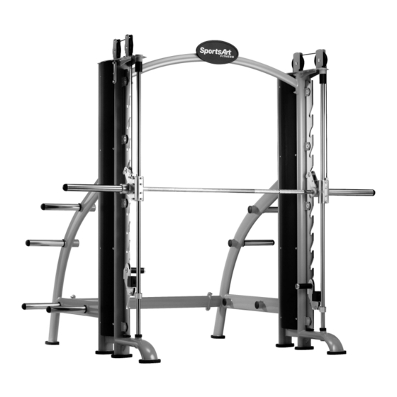
- Page 1 A983 OWNER'S MANUAL ASSEMBLY INSTRUCTIONS MITH ACHINE...
- Page 2 A. Safety Instructions: ˙ Read all cautions/warnings and obtain proper instruction on use of the machines prior to using. Use appropriate positioning and controlled movements. ˙ Assemble and operate the machine on a solid, level surface. DO NOT use outdoors or near water. ˙...
- Page 3 B. Introduction Pulley holder Connector A Pulley Covers Main frame Hook plate Lifting rod Sliding rod Guide bushing Hook Weight plate rod Bullet end cap B Bullet end cap A Set springs Connector B Elevation connector Stack Track Linear bearing sleeve Weight stack Foot pad Safety pad...
- Page 4 C. List of Parts 1.Two main frames 2.One connector A 3.One connector B 4.Two pulley holders 5.Eight weight plate rods 6.One lifting rod 7.Two bullet end caps B 8.Two set springs 9.One L shaped hex key wrench M4 10.One L shaped hex key wrench M5 11.One L shaped hex key wrench M6 12.One L shaped hex key wrench M10 13.One double-end open wrench 8mm*17mm...
- Page 5 1. Pulley holder-Right 11. Weight plate rod *8 2. Elevation connector set-Right 12. Elevation connector set-Left 3. Assembly parts package *2 13. Weight stack *2 4. Main frame *2 14. Cover *4 5. Lifting rod 6. Connector A 7. Rear Frame-Right 8.
- Page 6 D. Assembly Instruction Installation of Rear Frame Step 1: Secure left rear frame onto the left frame as shown. Step 2: Repeat step 1 for right frame assembly. Nuts Flat washer Spring washer Screws...
- Page 7 Installation of Connector A & B Step 1: Secure left and right rear frames with connector B as shown below. Nuts Flat washer Spring washer Screws Screws Spring washer Flat washer Nuts Step 2: Secure left and right main frames with connector A as shown below. Screws Spring washer Fixing plate...
- Page 8 Weight plate rod installation (8 rods as shown) Step 1: Insert the weight plate rod into the rear frame as shown. Step 2: Secure with screws provided. Step 3: Repeat step1-2 for installation of the other 7 weight plate rods.
- Page 9 Installation of lifting rod Step 1: Put the lifting rod horizontally through the gap between the sliding rod and hook plate on both sides. Step 2: Hang the lifting rod onto the hook plate. The recommended height is from the 4 to the 6 shelf.
- Page 10 Step 4: Pull the linear bearing sleeves up and secure the parts with the elevation connectors on both sides as shown below. Flat washer Spring washer Screws Flat washer Spring washer Screws Screws Spring washer Flat washer Flat washer Spring washer Screws...
- Page 11 Step 5: Follow the instructions below to assemble the parts provided: 1.Assemble the plastic part provided onto the lifting rod handlebars. 2.Secure washers and screws. 3.Secure bullet end caps. 4.Secure the set springs.
- Page 12 Installation of cables and weight stacks Step 1: Loosen screws before removing covers. Step 2: Identify pulley assemblies as to left and right. Step 3: Secure pulley assemblies with the frame on both sides.
- Page 13 Step 4: Release the right side weight stack bands. Step 5: Pull the right side weight stack up just above M (the hole on the stack track), then use the tools provided to go through M to hold the stack. (Caution: Be careful not to pinch your fingers and hands.) Step 6: Hang the lifting rod on the highest shelf.
- Page 14 Step 7: Put the cable right through E, F, and G as shown. Step 8: Secure the cable with nuts after the cable goes through H as shown.
- Page 15 Step 9: Remove the tools. Step 10: Repeat steps 4-9 to install the left side. Step 11: Secure covers onto the frame. Step 12: Test if the lifting rod can go up and down smoothly. Note: The length between the left and right side frame should range from 1490-1497 cm as shown.
- Page 16 Test tip for left and right side frame assembly: Step 1. After completing the assembly, please hang the lifting rod on the top shelf. Does the hook fit perfectly in the hook plate? Then hang the lifting rod on the bottom shelf.
- Page 17 Cautions: The guiding sets "A" & "B" should stick to the hook plate while in operation. Improper placement would not only damage the machine, but also lose its intended efficacy of protection.
- Page 18 E.MAINTENANCE SCHEDULE (A983) Maintenance Schedule Exterior Clean. Inspect for looseness. Screws Tighten if needed. Guide rod Wipe clean with a damp cloth. Inspect for wear and Cable breakage.
- Page 19 F.MAINTENANCE TASK LIST (STRENGTH PRODUCTS): Like cars, fitness products require maintenance. Regular maintenance extends product life, and failure to maintain products can void the manufacturer's warranty. Copy the maintenance log sheet, and record maintenance work for each fitness product. Daily tasks 1.
- Page 20 G.MAINTENANCE ONE-YEAR MAINTENANCE LOG: Facility : Supervisor: Product Model Number : Serial Number: Start Date: End Date: Daily Tasks Weeks 8-14 Weeks 1-7 Weeks 15-21 Weeks 22-28 Completed Daily Tasks Weeks 29-35 Weeks 36-42 Weeks 43-49 Weeks 50-52 Completed Weeks 1-7 Weeks 8-14 Weeks 15-21 Weekly Tasks...
Need help?
Do you have a question about the A983 and is the answer not in the manual?
Questions and answers