
Subscribe to Our Youtube Channel
Related Manuals for Beko BEKOKAT CC-1200


Summary of Contents for Beko BEKOKAT CC-1200
- Page 1 EN – English Installation and operation manual ® BEKOKAT CC-1200 Catalytic converter For removing oil from compressed air Version 11 bar...
- Page 2 ® Installation and Operation Manual BEKOKAT Manufacturer: BEKO TECHNOLOGIES GMBH Im Taubental 7 D-41468 Neuss Tel. +49 2131 9880 www.beko-technologies.com Issue date: 07-2018 Version: Document-No.: 11-043 Dear customer ® Thank you for purchasing the BEKOKAT CC-1200 Catalytic Converter. Please follow our instructions and read this installation and operation manual carefully before installing and comissioning the catalytic converter.
-
Page 3: Table Of Contents
® Installation and Operation Manual BEKOKAT Table of contents General ..........................6 1.1 Pictograms and symbols ..................7 1.2 Signal words according to ISO 3864 and ANSI Z.535 ......... 8 1.3 General safety instructions .................. 9 1.4 Special notes for pressurised equipment according to Pressure Directive 2014/68/EU ...................... - Page 4 ® Installation and Operation Manual BEKOKAT 4.3 Bypass System ....................44 4.4 Installation examples ..................45 4.4.1 Compressed air treatment with a BEKOKAT ® catalytic converter ....... 45 4.4.2 BEKOKAT ® with Bypass ..................... 46 4.4.3 BEKOKAT ® with DRYPOINT ®...
- Page 5 ® Installation and Operation Manual BEKOKAT 6.10 RESET for time relay K1T .................. 77 Maintenance ........................78 7.1 Safety instructions ....................78 7.2 Decommissioning for service, maintenance or repair ........80 7.3 Maintenance schedule ..................81 7.4 Recurring inspections ..................82 7.5 ...
-
Page 6: General
This documentation, including all its parts, is protected by copyright. Any use or modification outside the strict limits of the copyright law is prohibited and punishable without the consent of BEKO TECHNOLOGIES GmbH. This applies, in particular, to duplication, reproduction, translation, microfilming and storage and processing in electronic systems. -
Page 7: Pictograms And Symbols
® Installation and Operation Manual BEKOKAT Pictograms and symbols The safety instructions in this operating instructions are intended to prevent hazards. They are located in the operating manual before an action / work / activity is described which can create a hazard. -
Page 8: Signal Words According To Iso 3864 And Ansi Z.535
® Installation and Operation Manual BEKOKAT Environmentally friendly material. The packaging material is recyclable. Dispose of it according to the applicable statutory regulations. Signal words according to ISO 3864 and ANSI Z.535 Imminent danger DANGER Consequences of non-compliance: serious or even fatal injury Potential danger WARNING Consequences of non-compliance: possibly serious or even fatal injury... -
Page 9: General Safety Instructions
® Installation and Operation Manual BEKOKAT General safety instructions NOTE Installation and operation manual Before reading this manual, make sure that it refers to your plant model. This document contains important information and instructions for the safe operation of the plant. Non-compliance with these installation and operating instructions can cause hazards for people and the plant. - Page 10 ® Installation and Operation Manual BEKOKAT DANGER Compressed air! Gases under high pressure Any contact with escaping compressed gas or not secured system parts will create danger of serious injuries or death. Only executeinstallation work and maintenance work in a depressurised status.
- Page 11 ® Installation and Operation Manual BEKOKAT DANGER Electric power Touchable conductive parts can lead to dangerous voltages / mains voltage during installation and maintenance or in case of defects. Hazard resulting in of serious or even fatal injury from electric shock when coming into contact with uninsulated parts or mains voltage.
- Page 12 ® Installation and Operation Manual BEKOKAT WARNING Operation of plant outside limit range If the specified limits are undershot and/or exceeded, then function and operating malfunctions could occur and cause danger for people and material. ® BEKOKAT may only be used in accordance with its intended use and within the permitted limiting values stated on the rating plate as well as in the technical data.
- Page 13 ® Installation and Operation Manual BEKOKAT WARNING Fire Adjust the fire extinguishing measures to the working environment. Never use water in a full jet for safety reasons. Wear a respiratory mask independent of ambient air. DANGER Excessive pressure / temperature ...
- Page 14 If you have any queries regarding the content of this installation and operating manual, please contact BEKO TECHNOLOGIES GMBH. The system must only be operated and serviced according to the information in the operating instructions to ensure safe operation.
-
Page 15: Special Notes For Pressurised Equipment According To Pressure Directive 2014/68/Eu
® Installation and Operation Manual BEKOKAT Special notes for pressurised equipment according to Pressure Directive 2014/68/EU ® Proper utilisation of the BEKOKAT is a fundamental prerequisite for safe operation. The owner and/or operator must therefore always proceed as follows: ®... - Page 16 ® Installation and Operation Manual BEKOKAT Unauthorised interference with the device can cause injury or damage to the pressure equipment. Do not make any unauthorised modifications to the device and use the pressure equipment only for the intended purpose. ...
-
Page 17: Special Safety Instructions
® Installation and Operation Manual BEKOKAT Special safety instructions DANGER Compressed air parameters Exceeding the maximum pressure can cause damage to the plant. Observe the maximum permissible pressure specified on the rating plate! NOTE Endangered functional safety Faulty installation can endanger the functional safety and have a negative effect on maintenance work. -
Page 18: Residual Risk
® Installation and Operation Manual BEKOKAT Residual risk The BEKOKAT ® catalytic converter corresponds to the current specifications of safety technology. Nevertheless, certain residual risks remain: Hazards caused by incorrect transport and storage. Hazards caused by electrical voltage when using improper electrical connection cables or touching live parts with the control box open. -
Page 19: Intended Use
® Installation and Operation Manual BEKOKAT Intended use The BEKOKAT ® is used to remove oil from the compressed air. The compressed air must be free of aggressive, corrosive, caustic, toxic, flammable or oxidising substances. Any other utilisation is thereby considered to be non-intended use. The manufacturer shall not be liable for damage caused by improper use. - Page 20 ® Installation and Operation Manual BEKOKAT WARNING Danger caused by incorrect use The BEKOKAT ® complies with the latest technology and is safe to operate. There are however some residual risks which may result from the system if improperly used and operated by untrained personnel. Improper use includes: ...
-
Page 21: Legal Warranty And Liability For Property Defects
® Installation and Operation Manual BEKOKAT Legal warranty and liability for property defects All warranty claims will be voided if BEKOKAT ® is not utilised in accordance to its intended use or in excess of the specifications stated in the technical data; this particularly includes the following: ... -
Page 22: Transport And Storage
® Installation and Operation Manual BEKOKAT Transport and Storage Safety instructions CAUTION Danger due to improper transport! Incorrect transport or storage may cause damage to the system. The BEKOKAT ® must only be transported and stored by authorised and suitably trained specialist technical personnel. ... - Page 23 ® Installation and Operation Manual BEKOKAT The BEKOKAT ® must be stored in the original packaging in a closed, dry and frost-free room. Ensure that the ambient conditions do not undershoot and/or exceed details information on the type plate. ...
-
Page 24: Transport
Therefore, always inspect the BEKOKAT for possible transport damage after transport and removal of the packaging material. The freight forwarder and BEKO TECHNOLOGIES or the BEKO TECHNOLOGIES representative must be notified immediately of any damage. Always provide suitable lifting equipment for transport and installation. -
Page 25: Requirements For The Site
® Installation and Operation Manual BEKOKAT Requirements for the site The installation location must fulfil the following requirements: The installation will be executed within a building. The BEKOKAT ® must be protected from exposure to moisture. The ambient temperature must not exceed the specifications on the rating plate. ... -
Page 26: Product Information And System Description
® Installation and Operation Manual BEKOKAT Product information and system description Type plate BEKO TECHNOLOGIES GMBH Im Taubental 7 D-41468 Neuss, GERMANY Phone: +49 2131 988-0 www.beko-technologies.com Year of Construction Product name BEKOKAT ® CC-1200 Serial No. Model: 4015280 Inspection... -
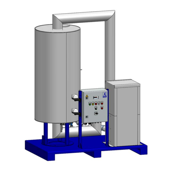
Page 27: Product View
® Installation and Operation Manual BEKOKAT Product view V01 / 11-043 27 / 88... -
Page 28: Function Description Of The Catalytic Converter
® Installation and Operation Manual BEKOKAT Function description of the catalytic converter The BEKOKAT ® catalytic converter has been developed for the treatment of oily compressed air. ® The BEKOKAT catalytic converter can be installed and operated behind compressors of any type (reciprocating compressors, screw compressors, etc.) provided the maximum operating conditions specified are observed. - Page 29 ® Installation and Operation Manual BEKOKAT The air constituents can be in gas, vapour and aerosol form and are converted into carbon ® dioxide (CO ) and water (H O) in the BEKOKAT The incoming oil-saturated air from the compressor normally has a temperature of 10 K above the ambient temperature.
-
Page 30: Set-Up Description
® Installation and Operation Manual BEKOKAT Set-up Description 1 Plate heat exchanger for air heating 2 Catalytic converter reactor (converter) with catalyst agent 3 Temperature Control Unit 4 Heating system 5 Safety temperature monitor F01 6 Safety temperature limiter F02 7 Incline seat valve V1 Compressed air INLET 8 Incline seat valves V2 Compressed air CONDENSATE DRAIN, oil and grease-free 9 Safety Valves X4... -
Page 31: Description Of The Components
® Installation and Operation Manual BEKOKAT Description of the components 3.5.1 Heat exchanger plate (1) The heat exchanger plate is designed as an air-to-air heat exchanger. The cold compressed air entering into the assembly unit is heated by means of emerging from the reactor compressed air at high temperatures accordingly. -
Page 32: Heating System (4)
® Installation and Operation Manual BEKOKAT CAUTION Exceeding or falling below temperatures If the temperature falls below T <60 °C, T> 200 °C, a warning signal sounds and the display flashes. If the set alarm temperatures are exceeding or falling below the set alarm temperatures, valves V1 and V2 are closed at the inlet and ®... -
Page 33: Incline Seat Valves (7/8)
® Installation and Operation Manual BEKOKAT 3.5.5 Incline seat valves (7/8) In order to ensure the safe operation of the assembly unit (even in the unlikely event of an oil breakthrough), the incline seat valves V1 and V2 are installed in the inlet and condensate drain line for automatic shut-off of the compressed air. -
Page 34: Safety Valve (9)
® Installation and Operation Manual BEKOKAT When the incline seat valves V1 and V2 open, then the position indicators of the valves (2) move upwards out of the drive of the valves. 3.5.6 Safety valve (9) Closing valves V1 and V2 can lead to a pressure increase above the permissible 11 bar in the event of a temperature overrun in the system. -
Page 35: Safety Equipment Against Temperature Overruns (5/6)
® Installation and Operation Manual BEKOKAT 3.5.7 Safety equipment against temperature overruns (5/6) The reactor tank has been calculated and tested for a maximum operating temperature of + 300 °C. There are 2 safety thermostats installed on the outer wall of the container. The temperature monitor TW (5) is installed in the upper part of the reactor on the tank wall and opens when a set limit value of + 260 °C is exceeded In this situation, the indicator light H2 turns yellow and the alarm F01 is displayed. - Page 36 ® Installation and Operation Manual BEKOKAT The safety temperature limiter STW (6) is installed at the bottom of the reactor on the tank wall and opens when a set limit of + 300 °C is exceeded. In this case, the H3 indicator lights red and alarm F02 is displayed. After falling below the limit value, the reset is carried out by means of automatic RESET STW F02.
- Page 37 ® Installation and Operation Manual BEKOKAT The current supply to the heaters is interrupted as soon as the set limit of 235°C is reached. It does not matter whether the exceeded temperature was detected in the upper or lower area of the container.
-
Page 38: Technical Data
® Installation and Operation Manual BEKOKAT Technical data ® Technical data BEKOKAT ® Name BEKOKAT CC-1200 Model BEKOKAT ® catalytic converter Compressed air Fluid group 2 according to DGRL 2014/68/EU Up to 100% saturated, free of liquid water or Medium condensate Free of aggressive, corrosive, caustic, toxic, flammable or combustion supporting materials... - Page 39 ® Installation and Operation Manual BEKOKAT 1) At inlet temperatures above + 45 °C, temperatures> + 60 °C may occur at the outlet of ® the BEKOKAT . Please pay attention to the corresponding design of the following components. Technical data BEKOKAT ®...
-
Page 40: Applied Eu Directives And Harmonised Standards
Electrical equipment for furnaces and related equipment - Part 1: Provisions for application planning and construction The declaration of conformity is enclosed separately with the assembly unit or can be requested from BEKO Technologies GmbH. 40 / 88 V01 / 11-043... -
Page 41: Installation
® Installation and Operation Manual BEKOKAT Installation Safety instructions CAUTION Quality of compressed air The compressed air must be free of aggressive, corrosive, caustic, toxic, flammable or oxidising substances. Compressed air up to max. 100% saturated, free of liquid water or condensate. - Page 42 ® Installation and Operation Manual BEKOKAT NOTE Endangered functional safety Faulty installation can endanger the functional safety and have a negative effect on maintenance work. The clear width of the pipe connection must be at least as large as ®...
-
Page 43: Fundamental Requirements For The Installation
® Installation and Operation Manual BEKOKAT Fundamental requirements for the installation Set up the converter so that the system is easily accessible from the sides and from the top. Ensure a suitable base (sufficiently stable and level) during the setting up process. The blow-off direction of the safety valve must be away from traffic routes. -
Page 44: Bypass System
® Installation and Operation Manual BEKOKAT Bypass System The bypass system should be equipped with an automatic bypass valve and installed as follows: ® BEKOKAT ® ® CLEARPOINT particle filter as afterfilter with BEKOMAT ® ® CLEARPOINT ultra-fine filter as bypass filter with BEKOMAT ®... -
Page 45: Installation Examples
® Installation and Operation Manual BEKOKAT Installation examples ® 4.4.1 Compressed air treatment with a BEKOKAT catalytic converter Compressed air compressor (oil lubricated) ® Water separator with condensate arrester BEKOMAT Compressed air vessel ® Condensate arrester BEKOMAT for boiler drainage Universal filter (G) with BEKOMAT ®... -
Page 46: Bekokat ® With Bypass
® Installation and Operation Manual BEKOKAT 4.4.2 BEKOKAT ® with Bypass ® BEKOKAT CC-1200 Bypass with automatic valve Prefilter CLEARPOINT M018SWT Activated carbon filter CLEARPOINT M018AWM NOTE Installation Please note that the activated carbon filter in the bypass only has a service life of approx. -
Page 47: Bekokat ® With Drypoint ® Refrigeration Dryer And Metpoint ® Ocv
® Installation and Operation Manual BEKOKAT 4.4.3 BEKOKAT ® with DRYPOINT ® refrigeration dryer and METPOINT ® ® In general, the integration of the BEKOKAT into your system is recommended as a complete unit with the corresponding drying of the compressed air and the monitoring of ®... -
Page 48: Installation Of Compressed Air Connection
® Installation and Operation Manual BEKOKAT Installation of compressed air connection The compressed air connection of the BEKOKAT ® is located on the valves for inlet and condensate drain (see illustration). The connection is designed as a cylindrical internal thread Rp 2 1/2 " in accordance to DIN EN 10226-1. -
Page 49: Electrical Installation
® Installation and Operation Manual BEKOKAT Electrical installation 4.6.1 Safety instructions DANGER Electric power Touchable conductive parts can lead to dangerous voltages / mains voltage during installation and maintenance or in case of defects. Hazard resulting in of serious or even fatal injury from electric shock when coming into contact with uninsulated parts or mains voltage. - Page 50 ® Installation and Operation Manual BEKOKAT DANGER Operation without earth connection If there is a missing earth connection (protective earth), there is a danger that mains voltage components might become energised in case of errors. These will pose a risk of serious or even fatal injury. Earth connection takes place in this assembly unit via the mains supply line.
- Page 51 ® Installation and Operation Manual BEKOKAT DANGER Lack of EMERGENCY-STOP Switch According to DIN EN 50156-1, installation of an EMERGENCY STOP switch / EMERGENCY STOP device is required. It is the responsibility of the operator to install an EMERGENCY STOP button. ...
-
Page 52: 4.6.2 Electrical Connections
® Installation and Operation Manual BEKOKAT 4.6.2 Electrical connections ® On the lower side of the control box of the BEKOKAT are the cable glands for the electrical and signal connections. Here, the power supply lines and the potential-free alarm contact for the operating message are connected. -
Page 53: 4.6.3 Terminals For Electrical Connections
® Installation and Operation Manual BEKOKAT 4.6.3 Terminals for electrical connections All electrical connections are screw terminals. Open the control box, feed the cables through the screw connections into the control box and close the wiring according to the circuit diagram. Then firmly tighten the cable glands. -
Page 54: 4.6.4 Emergency Stop Switch / Emergency Stop Device
® Installation and Operation Manual BEKOKAT 4.6.4 EMERGENCY STOP switch / EMERGENCY STOP device Install an EMERGENCY STOP switch. In accordance with DIN EN 50156-1, emergency shut-down devices must meet the following requirements: They must be located in an easily accessible, safe place outside the room in which ®... -
Page 55: Commissioning
® Installation and Operation Manual BEKOKAT Commissioning Safety instructions DANGER Compressed air! Gases under high pressure Any contact with escaping compressed gas or not secured system parts will create danger of serious injuries or death. Only executeinstallation work and maintenance work in a depressurised status. - Page 56 ® Installation and Operation Manual BEKOKAT WARNING Hot surface Risk of injury to people property damage - risk of fire! Before carrying out any work on BEKOKAT ® , allow the system to cool down! Secure and mark the accessible places. WARNING Smoke Detection ...
-
Page 57: Inspection Before Commissioning
® Installation and Operation Manual BEKOKAT Inspection before commissioning The relevant country-specific regulations must be observed with regard to testing prior to commissioning. Implement a risk assessment in accordance with the applicable national guidelines. Safety-related technical inspections must be executed in accordance with national regulations. -
Page 58: Operation
® Installation and Operation Manual BEKOKAT Operation NOTE Safe operation The assembly unit must only be operated and serviced according to the information in the operating instructions to ensure safe operation. In addition to these instructions, always comply with the required statutory regulations for the application cases for system operation and company safety regulations as well as accident prevention regulations. -
Page 59: Electric Control
® Installation and Operation Manual BEKOKAT 5.3.1 Electric control Designation Description Display Main switch Start switch Temperature control unit Converter in operation "Green" indicator light ALARM with AUTO-RESET "Yellow" indicator light Temperature monitor TW ALARM with AUTO-RESET "RED" indicator light Safety Temperature Monitor STW Reactor heating phase "White"... -
Page 60: Settings
® Installation and Operation Manual BEKOKAT 5.3.2 Settings Designation Function On/off control, Setpoint switching and/or coupling FUNCTION KEY 1 to an output relay. After mains interruption the Default setting status remains stored. Pressing this key enlarges the parameter or KEY OPEN parameter value or scrolls through the parameter list. -
Page 61: Initial Commissioning
® Installation and Operation Manual BEKOKAT Initial commissioning After installation has been completed, proceed as follows for commissioning of the ® BEKOKAT Ensure that the pipework system is free of impurities. Inspect the compliance with the safety instructions relating to the quality of the compressed air. - Page 62 ® Installation and Operation Manual BEKOKAT 10th After a heating phase of about 21 hours, the target temperature of + 150 °C is set in the catalytic bed. The white indicator goes out and the green "Reactor ON" (H1) indicator comes on. The compressed air supply is automatically opened via the solenoid valve Y1.
-
Page 63: Notes On The Reactor Temperature During Commissioning
® Installation and Operation Manual BEKOKAT Notes on the reactor temperature during commissioning During commissioning of the BEKOKAT ® , the reactor temperature may rise above + 200 °C. ® This condition usually occurs when the commissioning of the BEKOKAT takes place in stand- by mode, i.e. - Page 64 ® Installation and Operation Manual BEKOKAT CAUTION Reactor temperature> + 200 °C Rise in reactor temperature to> + 200 °C during commissioning The increase of the reactor temperature to> + 200 °C during commissioning is not a malfunction. If the reactor temperature does not drop despite flowing through with compressed air, then it is a malfunction incident and the system must be shut down and checked in any case.
-
Page 65: Notes On The Operation Of The Bekokat
+ 160 °C. The BEKOKAT ® works fully automatically during operation. If a heating system fails, please contact the BEKO customer service. If faults occur during operation, please inform the responsible service technician. V01 / 11-043 65 / 88... -
Page 66: Notes On Reactor Temperature During Operation
In these cases, a change in the reactor set point temperature is possible to minimise the thermal load on the system and energy consumption. The setpoint can be reduced in increments of 5 K to approx. + 140 °C (see chapter 5.3.2). Please consult the BEKO TECHNOLOGIES service. DANGER Reactor temperature> + 200 °C shown on the display reactor temperature>... -
Page 67: Re-Commissioning After Shut Down
® Installation and Operation Manual BEKOKAT Re-commissioning after shut down If the BEKOKAT ® is only put back into operation after a long downtime, proceed as with initial commissioning. ® Check, particularly after maintenance or repair, if the BEKOKAT is fully piped and electrically connected. -
Page 68: Troubleshooting And Remedying Malfunctions
® Installation and Operation Manual BEKOKAT Troubleshooting and remedying malfunctions Safety instructions WARNING Hot surface Risk of injury to people property damage - risk of fire! ® Before carrying out any work on BEKOKAT , allow the system to cool down! ... -
Page 69: Reactor Temperature> + 200 °C
® Installation and Operation Manual BEKOKAT Reactor temperature> + 200 °C Malfunction image The reactor temperature rises during operation above T> + 200 °C. Close valves V1 / V2. The compressed air supply is interrupted. As soon as the valves close, the potential-free alarm contact is activated, signalling the fault by means of an external display (warning signal, indicator light, etc.). -
Page 70: Reactor Temperature> + 60 °C
® Installation and Operation Manual BEKOKAT Reactor temperature> + 60 °C Malfunction image The reactor temperature drops below T <+ 60 °C during operation. Close valves V1 / V2 as complete catalysis can not be ensured. The compressed air supply is interrupted. As soon as the valves close, the potential-free alarm contact is activated, signalling the fault by means of an external display (warning signal, indicator light, etc.). -
Page 71: Safety Temperature Monitor (Tw) Activated
® Installation and Operation Manual BEKOKAT Safety temperature monitor (TW) activated Malfunction image The safety temperature monitor (TW) of the heating system of the reactor responds, the temperature at the container tank wall in the upper range is T> + 260 °C. Cause Measure The setpoint of the reactor temperature (in... -
Page 72: Safety Temperature Monitor (Stw) Activated
® Installation and Operation Manual BEKOKAT Safety temperature monitor (STW) activated Malfunction image The safety temperature monitor (STW) of the heating system of the reactor responds, the temperature at the container tank wall in the lower area is T> + 300 °C. Cause Measure The setpoint of the reactor temperature (in... -
Page 73: Short-Term Power Failure
® Installation and Operation Manual BEKOKAT Short-term power failure Malfunction image Close valves V1 / V2. The current supply is interrupted. No alarm is displayed. Cause Measure Interruption of the voltage supply. The valves close automatically. When the power is restored, the time of approx. -
Page 74: Error Display
Cause Measure Error in the temperature sensor Check temperature sensor. Replace temperature sensor if necessary. Please contact the BEKO TECHNOLOGIES service. Capillary break in the thermostat Check thermostat. Replace temperature sensor if necessary. Please contact the BEKO TECHNOLOGIES service. -
Page 75: Defective Contactor Or Defective Relay Module
Defective contactor or defective relay module Malfunction image Indicator "H6" lights up Cause Measure Power contactor K1.1 or K1.2 blocked Check contactor and replace if necessary. Please contact the BEKO TECHNOLOGIES service. Relay module K1.1A or K1.2A blocked Check relay module replace necessary. -
Page 76: Defective Fuse
Cause Measure Fuse F3 defective Check fuse and replace if necessary. Please contact the BEKO TECHNOLOGIES service. NOTE Skilled technical personnel All function tests, operation, installation, configuration and maintenance of the device must be carried out by authorised skilled personnel. -
Page 77: Reset For Time Relay K1T
There is a contactor K3A in the e-box (see E-plan attached). At a reactor temperature of> + 130 °C ... + 150 °C it is possible, in consultation with the service technician of BEKO TECHNOLOGIES, to actuate the RESET key of the K3A and thus to bridge the time relay. -
Page 78: Maintenance
® Installation and Operation Manual BEKOKAT Maintenance Safety instructions NOTE Maintenance works All maintenance work on the BEKOKAT ® may only be carried out with the catalytic converter switched off, depressurised and voltage-free. All function tests, operation, installation, configuration maintenance of the device must be carried out by authorised skilled personnel. - Page 79 ® Installation and Operation Manual BEKOKAT DANGER Electric power Touchable conductive parts can lead to dangerous voltages / mains voltage during installation and maintenance or in case of defects. Hazard resulting in of serious or even fatal injury from electric shock when coming into contact with uninsulated parts or mains voltage.
-
Page 80: Decommissioning For Service, Maintenance Or Repair
® Installation and Operation Manual BEKOKAT Decommissioning for service, maintenance or repair Always proceed as follows to decommission the plant for servicing, maintenance or repairs: ® Turn off the BEKOKAT master switch. 2nd Open the bypass-line (not included). ® Close the shut-off valves in front of and behind the BEKOKAT ®... -
Page 81: Maintenance Schedule
® Installation and Operation Manual BEKOKAT Maintenance schedule Carefully perform the maintenance according to the following points. Posit Monthl Annuall Activity Weekly Check display of SET and ACTUAL temperature. Inspect operating pressure. Inspect the volume flow rate. Implement a general visual inspection. Pay attention to unusual occurrences, damage... -
Page 82: Recurring Inspections
The annual maintenance of the BEKOKAT ® can only be performed by BEKO TECHNOLOGIES or by authorised skilled technical personnel allocated by the manufacturer. Recurring inspections The owner and/or operator is obliged to specify deadlines for the recurring inspections and, depending on the classification in the compressed air equipment category in accordance with the Pressure Equipment Directive, have these executed by an approved inspection body. -
Page 83: Exchange Of Catalyst Agent
The replacement of the catalyst granulate can only be carried out by BEKO TECHNOLOGIES or by authorised skilled technical personnel authorised by the manufacturer. The utilised catalyst agent is not subject to mandatory labelling in accordance to the Hazardous Substances Regulation. -
Page 84: Disposal
If BEKOKAT ® is not returned to BEKO TECHNOLOGIES GmbH for disposal, the components must be disposed of in accordance with the waste code (see Chapter 7.6). WARNING... -
Page 85: Appendix
® Installation and Operation Manual BEKOKAT Appendix The electrical plan is attached separately in the E-box. The declaration of conformity will be sent separately with the system documentation and is not an integral part of this delivery. V01 / 11-043 85 / 88... - Page 86 ® Installation and Operation Manual BEKOKAT 86 / 88 V01 / 11-043...
- Page 87 ® Installation and Operation Manual BEKOKAT V01 / 11-043 87 / 88...
-
Page 88: Service Addresses
Tel. +86 147 1537 0081 (China) tim.chan@beko-technologies.com Italia / Italy Polska / Poland ⽇本 / Japan BEKO TECHNOLOGIES S.r.l BEKO TECHNOLOGIES Sp. z o.o. BEKO TECHNOLOGIES K.K Via Peano 86/88 Ul. Pańska 73 KEIHIN THINK Building 8 Floor I - 10040 Leinì (TO)
Need help?
Do you have a question about the BEKOKAT CC-1200 and is the answer not in the manual?
Questions and answers