Table of Contents
Advertisement
Quick Links
Advertisement
Table of Contents

Related Manuals for Kübler SAEJ1939


Summary of Contents for Kübler SAEJ1939
- Page 1 R67059.0002 - 3 Inclinometer IN88 Manual...
-
Page 2: Table Of Contents
Table of Contents Kübler Group Table of Contents Document ........................General Information......................Target Group......................Symbols used / Classification of the Warnings and Safety instructions....Product Description ....................... Technical Data ......................Interface Description SAE J1939 ................Supported Standards and Protocols ............... Installation ........................ - Page 3 Kübler Group Table of Contents Process Data Description ..................5.5.1 Angle Longitudinal - IN88_Slope_Long ............ 5.5.2 Angle Lateral - IN88_Slope_Lat ..............5.5.3 Temperature - IN88_Temperature ............5.5.4 Overflow - IN88_Overflow ................. 26 5.5.5 Position - IN88_BackFront ................ 27 5.5.6 Orientation - IN88_Orientation ..............5.5.7 Error - IN88_Error ..................
-
Page 4: Document
1 Document Kübler Group 1 Document This document is the English translation of the original German version. Publisher Kübler Group, Fritz Kübler GmbH Schubertstraße 47 78054 Villingen-Schwenningen Germany www.kuebler.com Issue date 02/2021 Language version German is the original language © Copyright 2021, Kübler Group, Fritz Kübler GmbH Text sources... -
Page 5: General Information
Kübler Group 2 General Information 2 General Information Please read this document carefully before working with the product, mounting it or starting it up. 2.1 Target Group The device may only be planned, mounted, commissioned and serviced by persons having the following qualifications and fulfilling the following conditions: •... - Page 6 2 General Information Kübler Group NOTICE Classification: Additional information relating to the operation of the product, and hints and recommendations for efficient and trouble-free operation. 6 - EN HB SAE J1939 - IN88 - R67059.0002 - 03...
-
Page 7: Product Description
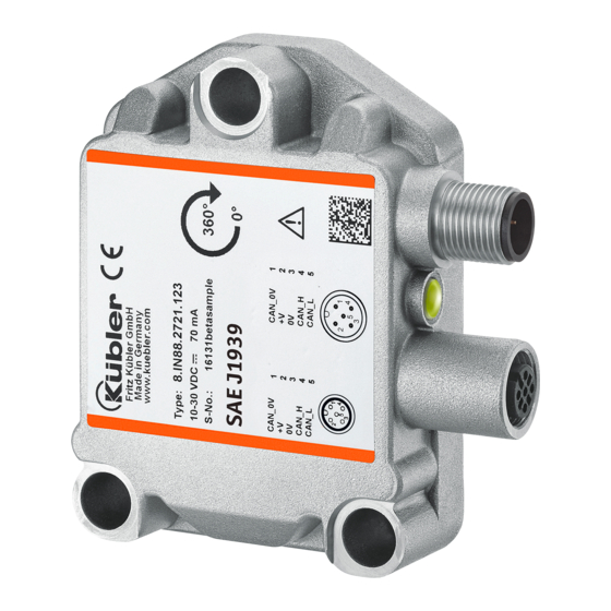
Kübler Group 3 Product Description 3 Product Description 3.1 Technical Data Operating, storage and -40 °C … +85 °C transport temperature range Supply voltage and current consumption 10 … 30 VDC 70 mA at 10 VDC 30 mA at 24 VDC 2 6 mA at 30 VDC 2-axis sensor: Measuring range per axis ±... - Page 8 3 Product Description Kübler Group IMG-ID: 118862859 Messages with a length exceeding 8 bytes are too large to suit in a single CAN data frame. So they must be divided in single packets by the transmitter to be then transmitted each in a CAN message.
-
Page 9: Supported Standards And Protocols
Kübler Group 3 Product Description IMG-ID: 118869643 3.3 Supported Standards and Protocols SAE J1939 with two PGs: • Configuration-receive PG (via CMDT transport protocol) • Position and status transmit PG (without transport protocol) The configuration PG allows performing node number allocation and CAN bit rate configuration directly via the CANbus. -
Page 10: Installation
4 Installation Kübler Group 4 Installation 4.1 Electrical Installation 4.1.1 General Information for the Connection ATTENTION Destruction of the device Before connecting or disconnecting the signal cable, always discon- nect the power supply and secure it against switching on again. NOTICE General safety instructions Make sure that the whole plant remains switched off during the elec-... -
Page 11: Connection Color Coding
Kübler Group 4 Installation EMC acc. to Criterion A Criterion B EN 61326-1 The device operates trouble-free, During a failure, a user data transmission proceeds disturbed transmission of the without disturbance, internally user data is allowed, internally stored data and configurations re- stored data and main preserved configurations remain preserved... -
Page 12: Connection Legend
4 Installation Kübler Group ATTENTION Destruction of the electronics When confectioning the sensor cable, always take care to ensure sufficient ESD protection. 4.1.4 Connection Legend Supply voltage +V DC Ground GND (0V) CAN_H: Positive CAN Signal (Dominant High) CAN_L: Negated CAN-Signal (Dominant Low) CAN_GND: CAN-Ground Connector housing (cable shield is applied on the connector housing), protective... -
Page 13: Electrical Features
Kübler Group 4 Installation NOTICE Connect the shield to the inclinometer housing • If possible, mount all cables with traction relief. • Check the maximum supply voltage on the device. 4.1.6 Electrical Features Display LEDs Interface SAE J1939 (CAN) Bus connection 1x M12 or 2x M12 Supply voltage 10 …... -
Page 14: Axes Orientation
4 Installation Kübler Group 4.2.2 Axes Orientation 1 dimensional - Rotation angle 2 dimensional - Orientation angle Z axis: "Longitudinal" (long) 0 … 360° X axis: "Longitudinal" (long) ±85° Y axis: "Lateral" (lat) ±85° 14 - EN HB SAE J1939 - IN88 - R67059.0002 - 03... -
Page 15: Commissioning And Operation
Kübler Group 5 Commissioning and Operation 5 Commissioning and Operation 5.1 Function and Status LED A multicolored LED signals the bus, operating and error status of the sensor. Green = BUS status Blue = BUS internal ERR display Red = BUS ERR display Display Meaning... -
Page 16: Changing The Parameters
5 Commissioning and Operation Kübler Group Signal name Standard value Resolution 100 (for 1-axis variant) 10 (for 2-axes variant) LongOperatingPar 0x02 (Scaling ON, Inversion OFF) LatOperatingPar 0x02 (Scaling ON, Inversion OFF) SensorCycleTime 100 (100 ms) BitRate 0 (250 kbps) CANBusTermination 1 (ON) J1939 address 0x20 (dec. -
Page 17: Protocol Features
Kübler Group 5 Commissioning and Operation • As specified in the J1939 protocol specification, the sensor waits 250 ms for a response to the address claim (e. g. in case its address is already occupied). • The sensor waits additional 250 ms for the setting of the internal measured values in order to avoid possible strong fluctuations of the measured values at the beginning (independent of CFG_Filter_Config). -
Page 18: Layout Of The Configuration Data Pg
5 Commissioning and Operation Kübler Group NOTICE PG number determination Upon customer request, other PG numbers can be set during sensor production, according to a special agreement with Kübler. The configuration data is - as specified in document SAE J1939/21 – transmitted via J1939 CMDT transfer. -
Page 19: Layout Of The Process Data Pg
Kübler Group 5 Commissioning and Operation NOTICE The following signals are not used for the 2-axes sensor: - INCLIN_CFG_LatOperatingPar - INCLIN_CFG_LatPresetActivate - INCLIN_CFG_LatPresetValue Please fill their values up with zeros. 5.3.3 Layout of the Process Data PG The process data is structured in blocks, as shown in the figure. The inclinometer transmits the process data on PGN 0xFFAB, which results in CAN-ID 0x18FFAB20 (Extended). -
Page 20: Configuration Parameters Description
5 Commissioning and Operation Kübler Group 5.4 Configuration Parameters Description 5.4.1 Cycle Time - INCLIN_CFG_TxCycleTime This signal allows setting in milliseconds the cycle time with which the process data (measured values) of the sensor is transmitted on the bus as a CAN frame. A value 0xFFFF retains the value stored so far in the sensor unchanged. -
Page 21: Resolution - Inclin_Cfg_Resolution
Kübler Group 5 Commissioning and Operation 5.4.5 Resolution - INCLIN_CFG_Resolution This signal sets the resolution of the inclinometer for all axes. Parameter "INCLIN_CFG_Resolution" influences measuring axes long16 and lateral16. Value Axis(axes) Value range of axis Value range of axes resolution IN88_SlopeLong for the IN88_SlopeLong and 1-axis sensor... -
Page 22: Preset Activation X Axis - Inclin_Slopelongpresetactivate
5 Commissioning and Operation Kübler Group 5.4.7 Preset Activation X Axis - INCLIN_SlopeLongPresetActivate If "INCLIN_SlopeLongPresetActivate" is set to 1, the preset function is triggered once immedi- ately upon receipt of the configuration PG and the value contained in "INCLIN_SlopeLongPre- setValue" is used for triggering the preset function. For all other values of "INCLIN_SlopeLongPresetActivate", "INCLIN_SlopeLongPresetValue"... -
Page 23: Preset Activation Y Axis - Inclin_Slopelatpresetactivate
Kübler Group 5 Commissioning and Operation • 0x01: Scaling off, Inversion on • 0x02: Scaling on, Inversion off • 0x03: Scaling on, Inversion on Scaling If scaling is enabled, the measured value is calculated first. The sensor thus takes into account a possibly set preset value when calculating the measured value. -
Page 24: Filter Setting - Inclin_Cfg_Filterconfig
5 Commissioning and Operation Kübler Group Recommendation: set this signal to 0 for the 1-axis variant. NOTICE Taking the preset into account The preset is only triggered when INCLIN_SlopeLatPresetActivate is set to 1. 5.4.12 Filter setting - INCLIN_CFG_FilterConfig This signal allows setting a low-pass filter. The starting point of the stop band frequency of the filter can be modified, or the filter can be totally disabled. -
Page 25: Process Data Description
Kübler Group 5 Commissioning and Operation 5.5 Process Data Description 5.5.1 Angle Longitudinal - IN88_Slope_Long 1-axes variant The inclinometer returns the value measured by the Z axis LONGITUDINAL16. The measured value depends on the settings of the configuration signals and on the sensor type. These values influence the calculation and the result. -
Page 26: Temperature - In88_Temperature
5 Commissioning and Operation Kübler Group 2-axes variant The inclinometer returns the value measured by the X axis LATERAL16. The measured value depends on the settings of the configuration signals and on the sensor type. These values influ- ence the calculation and the result. Byte 0 Byte 1 …... -
Page 27: Position - In88_Backfront
Kübler Group 5 Commissioning and Operation Value Meaning Sensor positioned within the valid measuring range > -85.00° & <+85.00° Sensor positioned outside of the positive measuring range > +85.00° Sensor positioned outside of the negative measuring range < -85.00° 5.5.5 Position - IN88_BackFront Returns the position of the sensor. -
Page 28: Error - In88_Error
5 Commissioning and Operation Kübler Group 2-axes variant For the 2-axes sensor, the quadrants refer to the 4 axis directions: +X, -X, +Y, -Y. IMG-ID: 9007199377711755 Value Meaning Tilting in the +Y direction Tilting in the -Y direction Tilting in the +X direction Tilting in the -X direction 5.5.7 Error - IN88_Error Returns the internal error status of the sensor. -
Page 29: Examples
Kübler Group 5 Commissioning and Operation NOTICE Behavior in case of connection loss. When resuming the connection with the sensor,it may happen that the sensor transmits a message that has not been transmitted yet be- cause of the loss of the connection. This is a normal behavior with CAN networks, but it may lead to an error in the control. - Page 30 5 Commissioning and Operation Kübler Group A CMDT connection must be set up first. The requesting control device has address 0x01 and the sensor has address 0x20. The parameters coded in the transmitted packet are: • Control byte: 0x10 • Message size: 0x10 •...
-
Page 31: Example: Resetting To Factory Settings
Kübler Group 5 Commissioning and Operation At the end of the transmission, the sensor confirms the successful transmission: Byte Byte Byte Byte Byte Byte Byte Byte Receipt EoMA, CAN-ID: 0x18EC0520 The receipt of the confirmation completes the configuration of the sensor. 5.6.2 Example: Resetting to Factory Settings In this example, the sensor is set to the default settings. - Page 32 5 Commissioning and Operation Kübler Group • Control byte: 0x10 • Message size: 0x10 • Total number of packets: 3 • Maximum number of packets: 0xFF • PG number: 0xEF00 • Source address: 0x01 • Destination address: 0x20 For this purpose, the following RTS packet must be transmitted to the sensor and the CTS an- swer from the sensor must be waited for: Byte Byte...
-
Page 33: Disposal
Kübler Group 6 Disposal 6 Disposal 6.1 Disposal Always dispose of unusable or irreparable devices in an environmentally sound manner, ac- cording to the country-specific provisions and in compliance with the waste disposal regulations in force. We will be glad to help you dispose of the devices, see chapter Contacts [} 34]. NOTICE Environmental damage in case of incorrect disposal Electrical waste, electronic components, lubricants and other auxili-... -
Page 34: Contact
7 Contact Kübler Group 7 Contact You want to contact us: Technical advice Kübler's worldwide applications team is available on site all over the world for technical advice, analysis or installation support. International support (English-speaking) +49 7720 3903 952 support@kuebler.com Kübler Germany +49 7720 3903 849 Kübler France +33 3 89 53 45 45 Kübler Italy... -
Page 35: Annex
Kübler Group 8 Annex 8 Annex 8.1 Angle calculation 8.1.1 1-axis inclinometer Euler angles In this setting, the output angle value is to be interpreted as an Euler angle. The "Euler angle Z" corresponds to the angle [°] by which the sensor has been rotated around the Z axis. NOTICE Comply with the maximum Z axis deflection. -
Page 36: Sensor Filter
8 Annex Kübler Group Indicating the two orientation angles describes the inclination of the coordinate system of the sensor with respect to the gravitational direction. The first value output corresponds to a rotation around the Y axis of the sensor and is called "Orientation angle Y". This value corresponds to the angle [°] formed by the gravity vector with the YZ plane of the sensor. - Page 37 Kübler Group 8 Annex Functioning The second index (j) is used for differentiation in case of several subsystems. A subsystem is described by equations, see below. The device uses 4 2nd order subsystems, resulting in an 8th order Butterworth filter filter. Xn is here the input signal, Yn is the filter output and simultaneously the input of another sub- system.
-
Page 38: Decimal / Hexadecimal Conversion Table
8 Annex Kübler Group 8.3 Decimal / Hexadecimal conversion table 38 - EN HB SAE J1939 - IN88 - R67059.0002 - 03... - Page 39 Kübler Group 8 Annex HB SAE J1939 - IN88 - R67059.0002 - 03 EN - 39...
-
Page 40: Glossary
Glossary Kübler Group Glossary PELV Broadcast Announce Message Protective Extra Low Voltage. Func- tional extra-low voltage with electrically safe isolation Commanded Address Parameter Group Controller Area Network Parameter Group Number Configuration Request To Send CMDT Connection Mode Data Transfer Clear To Send Diag Diagnostic Electromagnetic compatibility... - Page 41 Kübler Group Fritz Kübler GmbH Schubertstr. 47 D-78054 Villingen-Schwenningen Germany Phone +49 7720 3903-0 Fax +49 7720 21564 info@kuebler.com www.kuebler.com...
Need help?
Do you have a question about the SAEJ1939 and is the answer not in the manual?
Questions and answers