
Related Manuals for Kübler MWE20


Summary of Contents for Kübler MWE20
- Page 1 R60089.0009 - 03 Betriebsanleitung MWE20 / MWE21 Operation Manual Instructions d'utilisation...
- Page 2 R60089.0009 - 03...
- Page 3 ±5 mm 3 Nm SW10 [±0.2"] [26.6 lb-in] R60089.0009 - 03...
- Page 4 30° 1,0 Nm [8.85 lb-in] 1,0 Nm [8.85 lb-in] R60089.0009 - 03...
- Page 5 R60089.0009 - 03...
-
Page 6: Table Of Contents
Inbetriebnahme und Bedienung ......Inhaltsverzeichnis Instandhaltung............Dokument..............Reinigung des Messsystems ......Allgemeine Hinweise ..........Demontage ........... Verwendete Symbole / Klassifizierung der Wiedermontage ..........Warn- und Sicherheitshinweise ....Entsorgung ............. Vorbemerkung ..........Zielgruppe............. Kontakt ..............Transport / Einlagerung ........ Mitgeltende Dokumente........ Produktbeschreibung .......... -
Page 7: Dokument................................................................ 7 6 Instandhaltung
1 Dokument 2 Allgemeine Hinweise Dies ist die Originalbetriebsanleitung, Ausgangssprache Lesen Sie dieses Dokument sorgfältig, bevor Sie Deutsch. mit dem Produkt arbeiten, es montieren oder in Be- trieb nehmen. Herausgeber Kübler Group, Fritz Kübler GmbH Schubertstraße 47 Diese Betriebsanleitung leitet das technische Personal des 78054 Villingen-Schwenningen Maschinen- und Anlagenherstellers bzw. -
Page 8: Vorbemerkung .............................................. 8 7 Entsorgung
HINWEIS WARNUNG Klassifizierung: Klassifizierung: Dieses Symbol in Zusammenhang mit dem Signalwort WAR- Ergänzende Informationen zur Bedienung des Produktes so- NUNG warnt vor einer möglicherweise drohenden Gefahr für wie Tipps und Empfehlungen für einen effizienten und stö- das Leben und die Gesundheit von Personen. rungsfreien Betrieb. -
Page 9: Mitgeltende Dokumente
Die Lagerung muss trocken, staubfrei und gemäß den techni- Eine integrierte Feder in der Mechanik gewährleistet die für schen Daten erfolgen, siehe Kapitel eine zuverlässige Messwerterfassung notwendige Anpress- Technische Daten [} 10]. kraft des Messrades auf der Messgutoberfläche. Das System ist durch seine kompakte Bauweise auch für engste Ein- bauräume geeignet und lässt sich horizontal, vertikal oder 2.5 Mitgeltende Dokumente über Kopf schnell und einfach installieren. -
Page 10: Technische Daten
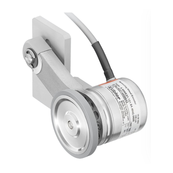
HINWEIS Konfiguration beachten Die Leistungsmerkmale und die mechanische Ausführung 8.MWE21.121.24.40B2.2000 des Produktes sind abhängig von der gewählten Konfigurati- on (gemäß Bestellschlüssel). 3.5.1 Messradsystem Mechanische Kennwerte Federarm IMG-ID: 45035996473336331 Arbeitstemperatur -20°C ... +70°C 1 Seriennummer 7 Hinweis Betriebsanlei- [-4°F … +158°F] tung beachten Schockfestigkeit gemäß 1000 m/s , 6 ms 2 Typ / Bestellschlüssel... -
Page 11: Installation
– RoHS: Regulations S.I. 2012/3032 4.1.1 Allgemeine Hinweise für die Montage Die Konformitätserklärung und alle Zertifikate zum Produkt HINWEIS finden Sie auf der Homepage. Werkzeuge www.kuebler.com/de/docu-finder Verwenden Sie für die Montage nur einem Qualitätssystem 4 Installation unterliegende, sowie geprüfte und kalibrierte Werkzeuge. 4.1 Mechanische Installation Schrauben und Schraubverbindungen ACHTUNG... - Page 12 Das Messradsystem wird wie im Datenblatt beschrieben aus- HINWEIS geliefert, d.h. es gibt eine definierte Ausrichtung vom Drehge- ber und der dazugehörigen Anschlusstechnik. Entspricht die- Messradauswahl se Ausrichtung nicht den Anforderungen innerhalb der Appli- Wählen Sie die Oberfläche des Messrads passend zu Ihrer kation, kann Folgendes bei der Montage adaptiert werden, Applikation aus.
-
Page 13: Änderung Der Befestigungsmöglichkeiten
h) Entfernen Sie den Innensechskantschlüssel. (4) Anpresskraft in Bezug zum Federweg i) Prüfen Sie die Kraft, die der Federarm ausübt, indem Sie 4.1.3 Änderung der Befestigungsmöglichkeiten das Messrad anheben. Beachten Sie dabei den maxima- len Federweg (5[} 3]). Um die Änderung durchzuführen, können Sie folgende Vor- j) Schieben Sie die Schutzkappe wieder auf den Federarm bereitungen treffen: auf bis diese einrastet (6[} 3]). -
Page 14: Inbetriebnahme Und Bedienung
• Beschichteten Schrauben Siehe Kapitel Kontakt [} 16]. • Klebstoffsicherungen Vor den Arbeiten • Schnorrscheiben • Schalten Sie die Energieversorgung ab und sichern Sie die- Als Manipulationsschutz wird eine zusätzliche Markierung der se gegen Wiedereinschalten. Befestigungsschrauben mit Sicherungslack oder ähnlichem • Trennen Sie anschließend die Energieversorgungsleitungen empfohlen. - Page 15 • Alle beschriebenen Montageschritte des Kapitels Installation [} 11] können umgesetzt werden. 7 Entsorgung Entsorgen Sie unbrauchbare oder irreparable Geräte immer umweltgerecht gemäß den länderspezifischen Vorgaben und gültigen Abfallbeseitigungsvorschriften. Gerne sind wir Ihnen bei der Entsorgung der Geräte behilflich. Siehe Kapitel Kontakt [} 16]. HINWEIS Umweltschäden bei falscher Entsorgung Elektroschrott, Elektronikkomponenten sowie Schmierstoffe...
-
Page 16: 8 Kontakt
Reparatur-Service / RMA-Formular 8 Kontakt Für Rücksendungen verpacken Sie das Produkt bitte ausrei- Sie wollen mit uns in Kontakt treten: chend und legen das ausgefüllte „Formblatt für Rücksendun- Technische Beratung gen“ bei. Für eine technische Beratung, Analyse oder Unterstützung www.kuebler.com/rma bei der Installation ist Kübler mit seinem weltweit agierenden Schicken Sie Ihre Rücksendung, unter Angabe der RMA-Re- Applikationsteam direkt vor Ort. - Page 17 Commissioning and Operation ......Table of Contents Maintenance............Document..............Cleaning the Measuring System....General Information ..........Disassembly ..........Symbols used / Classification of the Warn- Reassembly ..........ings and Safety instructions......Disposal ..............Preliminary Remark ........Target Group ..........Contact ..............Transport / Storage........
-
Page 18: Document................................................................ 18 6 Maintenance
1 Document 2 General Information This is the English translation of the original operation manual Please read this document carefully before working in German language. with the product, mounting it or starting it up. Publisher Kübler Group, Fritz Kübler GmbH Schubertstraße 47 These operating instructions guide the technical personnel of 78054 Villingen-Schwenningen... -
Page 19: Preliminary Remark ...................................... 19 7 Disposal
2.3 Target Group CAUTION The device may only be planned, mounted, commissioned Classification: and serviced by persons having the following qualifications This symbol, together with the signal word CAUTION , warns and fulfilling the following conditions: against a potential danger for the health of persons. •... -
Page 20: Product Description
3.4 Type plate www.kuebler.com/de/docu-finder Example of a type plate on the measuring wheel system: 3 Product Description 3.1 Function of a measuring wheel system A measuring wheel system is the ideal solution for reliable 8.MWE21.121.24.40B2.2000 speed, position and distance measurement in applications with linear movement. -
Page 21: Technical Data
3.5 Technical Data The technical data of the encoder can be found in the relev- ant operation manual/data sheet. NOTICE 3.5.2 Approvals Technical Data The product meets the following criteria: All technical data, as well as the mechanical and electrical •... -
Page 22: Installation
Screws and screwed connections 4 Installation Unless otherwise specified, a friction coefficient of 0.14 is re- 4.1 Mechanical Installation quired for all screwed connections. Unless otherwise spe- cified, a strength class of 8.8 (metric) or grade 5 (imperial) is required for all screws. ATTENTION The screws must be secured against loosening as described Damage to the device due to transport or storage... - Page 23 – Mounting bracket (order no. 8.0000.7000.0065) b) Mount the spring arm fastening screw on the mounting bracket / alternatively in the bore provided by the customer – Alternatively: bore (Ø 6,3 mm [1/4“]) provided by the (2[} 2]). customer • Materials (optional) c) Place the serrated washer and the hexagon nut on the –...
-
Page 24: Changing The Fastening Possibilities
4.1.2.3 Measuring Wheel Pressure Force b) The encoder can be mounted in 30° steps, paying atten- tion to the encoder cable outlet (B[} 4]). c) At the desired position, tighten the three M3 screws (C[} 4]). Mounting the measuring wheel: a) Place the measuring wheel on the encoder shaft and push it entirely towards the encoder until the stop (D[} 4]). -
Page 25: Commissioning And Operation
6.1 Cleaning the Measuring System 5 Commissioning and Operation If the measuring wheel becomes soiled in adverse environ- mental conditions, it can be cleaned according to the needs DANGER with a detergent suitable for the material. Use a lint-free cloth. Risk of injury due to rotating shafts 6.2 Disassembly Hair and loose clothing can be caught by rotating shafts. - Page 26 NOTICE Environmental damage in case of incorrect disposal Electrical waste, electronic components, lubricants and other auxiliary materials are subject to hazardous waste treatment. Problem substances may only be disposed of by licensed specialist companies. Dispose of disassembled device components as follows: •...
-
Page 27: 19 8 Contact
Repair service / RMA form 8 Contact In case of returns, please package the product sufficiently Sie wollen mit uns in Kontakt treten: and attach the completed "Returns form". Technical advice www.kuebler.com/rma Kübler's worldwide applications team is available on site all Send your return, stating the RMA reference, to the following over the world for technical advice, analysis or installation address:... - Page 28 Mise en service et utilisation......... Sommaire Maintenance............Document..............Nettoyage du système de mesure ....Informations générales.......... Démontage ........... Symboles utilisés / Classification des aver- Remontage ........... tissements et consignes de sécurité..... Elimination .............. Remarque préliminaire ......... Groupe cible ..........Contact ..............Transport / Entreposage.......
-
Page 29: Document................................................................ 29 6 Maintenance
1 Document 2 Informations générales Traduction française des instructions d'utilisation originales Lisez attentivement ce document avant de travailler en langue allemande. avec le produit, de le monter ou de la mettre en service. Editeur Kübler Group, Fritz Kübler GmbH Schubertstraße 47 Ces instructions d'utilisation guident le personnel technique 78054 Villingen-Schwenningen du constructeur et de l'exploitant de la machine ou de l'instal-... -
Page 30: Remarque Préliminaire ................................. 30 7 Elimination
2.3 Groupe cible ATTENTION L'appareil ne peut être utilisé dans un projet, monté, mis en Classification : service et entretenu que par des personnes disposant des qualifications et répondant aux conditions suivantes : Ce symbole, accompagné du mot ATTENTION, indique un risque potentiel pour la santé... -
Page 31: Description Du Produit
L’ensemble des documents comme les déclarations de • Sous l'eau. conformité originales ou les certificats correspondants • Dans des zones accessibles au public. peuvent être téléchargés depuis notre site Internet : • En dehors des spécifications de la fiche technique. www.kuebler.com/fr/docu-finder 3.4 Plaque signalétique 3 Description du produit... -
Page 32: Caractéristiques Techniques
3.5 Caractéristiques techniques Vous trouverez les caractéristiques technique du codeur dans les instructions d'utilisation/dans la fiche technique cor- respondantes. AVIS Caractéristiques techniques 3.5.2 Homologations Toutes les données techniques, ainsi que les caractéristiques Ce produit répond aux critères suivants : mécaniques et électriques, se trouvent dans les fiches tech- •... -
Page 33: Installation
Vis et liaisons vissées 4 Installation Sauf indication contraire, un coefficient de friction de 0,14 est 4.1 Installation mécanique requis pour toutes les liaisons vissées. Sauf indication contraire, une classe de résistance de 8,8 (métrique) ou de Grade 5 (impérial) est requise pour les vis. PRUDENCE Les vis doivent être protégées contre le desserrage comme Dommages à... - Page 34 – Equerre de fixation (Réf. de commande b) Monter la vis de fixation du bras à ressort sur l'équerre de 8.0000.7000.0065) fixation / en alternative dans le perçage du client (2[} 2]). – En alternative : perçage réalisé par le client (Ø 6,3 mm c) Placer la rondelle éventail et l'écrou hexagonal sur la vis [1/4“]) de fixation du bras à...
-
Page 35: Modification Des Possibilités De Montage
4.1.2.3 Force d'appui de la roue de mesure c) Lorsqu'il est dans la position souhaitée, serrer les trois vis M3 (C[} 4]). Montage de la roue de mesure : a) Enfiler la roue de mesure sur l'arbre du codeur et la pous- ser jusqu'en butée sur le codeur (D[} 4]). -
Page 36: Mise En Service Et Utilisation
• Déconnecter ensuite physiquement les lignes d'alimentation 5 Mise en service et utilisation en énergie. • Enlever les consommables et les produits auxiliaires, ainsi DANGER que les matériaux à traiter encore présents, du système de mesure. Risque de blessure par des arbres en rotation Les arbres en rotation peuvent happer les cheveux et les vê- 6.1 Nettoyage du système de mesure tements flottants. - Page 37 7 Elimination Toujours éliminer les appareils inutilisables ou irréparables de manière respectueuse de l'environnement, conformément aux dispositions nationales spécifiques et aux prescriptions en vigueur en matière d'élimination des déchets. Nous serons heureux de vous aider pour l'élimination des appareils. Voir chapitre Contact [} 38]. AVIS Dommages à...
-
Page 38: 30 8 Contact
Service Réparation / Formulaire RMA 8 Contact Pour les retours, merci d'emballer le produit de manière suffi- Vous voulez entrer en contact avec nous : sante et de joindre le « Formulaire de retour » rempli. Conseil technique www.kuebler.com/rma L'équipe d'application Kübler est à vos côtés sur site dans le Envoyer votre retour, en indiquant la référence RMA, à... - Page 39 Notizen / Notes...
- Page 40 Kübler Group Fritz Kübler GmbH Schubertstr. 47 D-78054 Villingen-Schwenningen Germany Phone +49 7720 3903-0 Fax +49 7720 21564 info@kuebler.com www.kuebler.com...
Need help?
Do you have a question about the MWE20 and is the answer not in the manual?
Questions and answers