Table of Contents
Advertisement
Quick Links
Advertisement
Table of Contents

Related Manuals for Kübler IN81


Summary of Contents for Kübler IN81
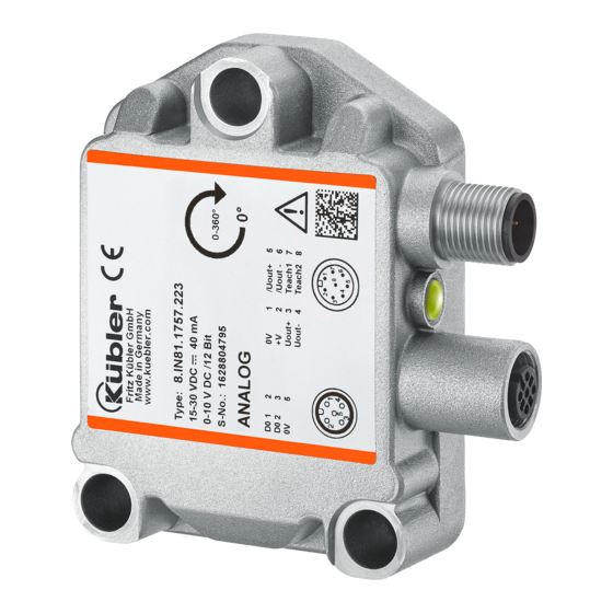
- Page 1 Manual Inclinometer IN81 Inclinometer 1-dimensional Inclinometer 2-dimensional...
- Page 2 Publisher Kübler Group, Fritz Kübler GmbH Schubertstr. 47 78054 Villingen-Schwenningen Germany www.kuebler.com Application support Phone +49 7720 3903-952 +49 7720 21564 support@kuebler.com Document no. R67029.0002 Document title Manual Language version EN - German is the original version Issue date 17.03.2017, Index 1 Copyright ©2016, Kübler Group, Fritz Kübler GmbH Legal information...
-
Page 3: Table Of Contents
1 Technical details and characteristics Table of contents Table of contents 1. Technical details and characteristics ................4 1.1 Working temperature range ....................4 1.2 Supply voltage and current consumption ................4 1.3 Load at the output / max. output current ................4 1.4 Hardware characteristics ...................... - Page 4 1 Technical details and characteristics 10. Scaling behavior of the analog measuring range of the 1-dimensional inclinometer . 29 R67029.0002 EN - 3...
-
Page 5: Technical Details And Characteristics
1 Technical details and characteristics Technical details and characteristics Working temperature range -40 … +85°C Supply voltage and current consumption Output: 4 … 20 mA: 10 … 30 VDC max. 30,0 mA 0 … 10 V: 15 … 30 VDC max. 30,0 mA 0 …... -
Page 6: Hardware Characteristics
1 Technical details and characteristics Hardware characteristics 2-dimensional sensor: Measuring range per axis max. ± 85° 1-dimensional sensor: Measuring range per axis max. ± 180° (0 … 360°) Analog output resolution (D/A) 4096 steps (12 bits) Internal cycle 20 ms Settling time 1 ms Table 1... -
Page 7: Orientation
1 Technical details and characteristics Orientation 1-dimensional 0 … 360° Figure 1 2-dimensional ±85° Figure 2 R67029.0002 EN - 6... -
Page 8: Electrical Installation - Supply Voltage
2 Electrical installation – Supply voltage Electrical installation – Supply voltage This chapter contains information about the electrical installation, configuration and commissioning of the inclinometer IN81 analog U/I. Figure 3 Electrical installation Switch off the plant! NOTICE Make sure that the whole plant remains switched off during the electrical installation. -
Page 9: Terminal Assignment
2 Electrical installation – Supply voltage Terminal assignment 1-dimensional Table 2 2-dimensional Table 3 R67029.0002 EN - 8... - Page 10 2 Electrical installation – Supply voltage Supply voltage +V DC Supply voltage GND (0V) Uout+ X X-axis voltage output Uout- X GND for X-axis voltage output Uout+ Y Y-axis voltage output Uout- Y GND for Y-axis voltage output Uout+ Voltage output, 1-axis version Uout- GND for voltage output, 1-axis version Uout +...
-
Page 11: Function And Status Led
3 Function and status LED Function and status LED The device is equipped with a RGB LED for displaying status and error messages LED display in normal operation Display RGB LED Meaning Addition LED off Device is not powered Green constantly Normal operation constantly... -
Page 12: Led Display In Programming Mode
3 Function and status LED LED display in programming mode Display RGB LED Meaning Addition Orange » Violet » Blue You are in the programming in repeating sequences mode » Green » Blue in a The device is reset to factory single sequence setting Orange... -
Page 13: Led Display In Scaling Mode: Switching Outputs (Optional!)
3 Function and status LED LED display in scaling mode: Switching outputs (OPTIONAL!) Display RGB LED Meaning Addition Green » Violet You selected measuring axis 1 in repeating order to set its switching output sequences » Violet You selected measuring axis 2 in Only available for repeating inclinometers with 2... -
Page 14: Standard Function
4 Standard function Standard function 1-dimensional inclinometer The single-axis inclinometer is factory-equipped with a measuring range of 0 … 360°. According to the selected output type, a linear output signal is emitted by the analog outputs. • Analog output 1: o increasing measurement signal for positive direction of movement. -
Page 15: 2-Dimensional Inclinometer
4 Standard function Example for a measuring range of 0 … 180°: Figure 5 2-dimensional inclinometer The 2-dimensional inclinometer is factory-set with a measuring range of +/-85°. Depending on the analog output type (4 … 20mA / 0 … 10V/…), a linearly increasing measurement signal is emitted for every measuring axis. -
Page 16: User Settings Overview
5 User settings overview User settings overview Normal operation T1 + T2 > 2 sek. PRESET PROG-Mode 1-dimensional 2-dimensional T1 + T2 >10 sek. 500ms AXIS 1 AXIS 1 AXIS 2 1000ms 50/50 50/50 T2 > 2 sek. RESET T1 > 2 sek. 6x100ms 6x100ms 6x100ms... -
Page 17: User Settings
6 User settings User settings The inclinometer can be adapted to the customer application by means of two teach inputs. The following functions are available to the user. They can be operated through the two teach inputs: • Preset function (set a new reference point) •... -
Page 18: Scaling The Analog Measuring Range
6 User settings 2-dimensional inclinometer Preset axis X (not available for measuring range +/- 85º!) Action RGB LED Description Initial state: Device The device is in normal operation and in factory setting. in normal operation, The X-axis is located in the measuring range of +/- 15°. constantly on axis X <= +/-15°... - Page 19 6 User settings 1-dimensional inclinometer Scale the measuring range within 0 … 360º Action RGB LED Description The device is in normal operation and in factory setting. Initial state: Device in normal constantly on operation Apply +V at teach inputs 1 & 2 for > 1sec. The device is switched to programming mode.
- Page 20 6 User settings 2-dimensional inclinometer Measuring range X axis within +/- 85º Action RGB LED Description The device is in normal operation and in factory setting. Initial state: Device in normal constantly on operation Apply +V at teach inputs 1 & 2 for > 1sec. The device is switched to programming mode.
- Page 21 6 User settings Measuring range Y axis within +/- 85º Action RGB LED Description The device is in normal operation and in factory setting. Initial state: Device in normal constantly on operation Apply +V at teach inputs 1 & 2 for > 1sec. The device is switched to programming mode.
-
Page 22: Setting The Switching Outputs
6 User settings Setting the switching outputs 1-dimensional inclinometer Setting the switching outputs 1 & 2 within 0 … 360º Action RGB LED Description The device is in normal operation and in factory setting. Initial state: Device in normal operation, constantly on axis Y <= +/-15°... - Page 23 6 User settings Apply +V at teach input 1 for > 1sec. The switching position for switching output 2 is saved. = > 1 Sec. The LED flashes 6 x green after successful saving of the switching position. In case of an error, the LED flashes 6 x red. The defined switching positions cannot be saved.
-
Page 24: Setting Of The Sensor Filter
6 User settings Apply +V at teach input 2 for > 1sec. The switching position for switching output 2 is saved. The LED flashes 6 x green after successful saving of the = > 1 Sec. switching position. In case of an error, the LED flashes 6 x in red. The defined switching positions cannot be saved. -
Page 25: Resetting To Factory Settings
6 User settings Filter level decrement Apply +V at teach input 2 for > 1sec. Filter level is decreased by -1. = > 1 Sec. The input is confirmed by 6 x Green flashing of the LED. Save filter level Apply +V at teach inputs 1 &... -
Page 26: Sensor Filter
7 Sensor filter Sensor filter Filter description 1st order: In electronics, low-pass filters are filters that let pass signal portions with frequencies lower than their limit frequency almost without attenuation and attenuate signal portions with higher frequencies. Pass Permissible area for area transfer characteristic Transition... - Page 27 7 Sensor filter Functioning The second index (j) is used for differentiation in case of several subsystems. A subsystem is described by equations, see below. The device uses 4 2nd order subsystems, resulting in an 8th order Butterworth filter. Figure 9 is here the input signal, Y is the filter output and simultaneously the input of another subsystem.
-
Page 28: Preset Function Restriction For The 2-Dimensional Inclinometer
8 Preset function restriction for the 2-dimensional inclinometer Preset function restriction for the 2- dimensional inclinometer Due to the limitation of the max. measuring range to +/- 85.00°, no preset function is available for a measuring range of > +/-70.00°. If a measuring range <... -
Page 29: Timeout In Programming Mode
9 Timeout in programming mode Timeout in programming mode If the inclinometer is switched to programming mode by actuating teach inputs 1 & 2 but no further function is selected, the inclinometer returns automatically to normal operation after 60 seconds. The inclinometer can also be switched back to normal operation by switching the supply voltage off and on again. - Page 30 10 Scaling behavior of the analog measuring range of the 1-dimensional inclinometer 10. Scaling behavior of the analog measuring range of the 1-dimensional inclinometer In the 1-dimensional inclinometer, the direction of movement of the measuring axis during the scaling process of a new analog measuring range is crucial. The lowest analog measurement value is always assigned to the defined starting position (example 0 …...
- Page 31 Kübler Group Fritz Kübler GmbH Schubertstr. 47 78054 Villingen-Schwenningen Germany Phone: +49 7720 3903-0 Fax: +49 7720 21564 info@kuebler.com www.kuebler.com...
Need help?
Do you have a question about the IN81 and is the answer not in the manual?
Questions and answers