
Related Manuals for Kübler IN88


Summary of Contents for Kübler IN88
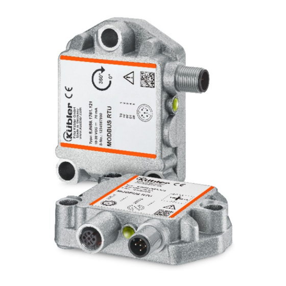
- Page 1 R67910.0002 Index 1 Manual Inclinometer IN88 Inclinometer 1-dimensional Inclinometer 2-dimensional...
- Page 2 Phone +49 7720 3903-952 +49 7720 21564 support@kuebler.com Document no. R67910.0002 Document title Manual – IN88 Modbus Language version English (ENG) - German is the original version Issue date 23.02.2017, R67910.0002 - Index 1 Copyright © 2018, Kübler Group, Fritz Kübler GmbH...
-
Page 3: Table Of Contents
Table of Contents Table of Contents Table of Contents List of Abbreviations 1. Contents ..........................1 2. Identification and maintenance functionality ..............2 3. Technical details and characteristics ................3 3.1 Working temperature range ....................3 3.2 Supply voltage and current consumption ................3 3.3 Hardware characteristics ...................... - Page 4 Table of Contents 9. Write Holding Register ..................... 18 10. Supported Modbus Function Codes in Project .............. 20 10.1 Function 03 Read Holding Registers General Description ........20 10.2 FUNCTION 16 (10 HEX) PRESET MULTIPLE REGISTERS ........20 11. Function code 03 ......................22 13.
-
Page 5: List Of Abbreviations
List of Abbreviations List of Abbreviations Abbreviation Meaning Cyclical Redundancy Check CRLF Carriage Return – Line Feed Error Hexadecimal Longitudinal Redundancy Check Protocol Data Unit Remote Terminal Unit R67910.0001... -
Page 6: Contents
1 Contents Contents This manual contains information about the IN88 inclinometers on the following topics: • Firmware and device file versions • Technical details and inclinometer characteristics • Supply voltage and current consumption • Hardware characteristics • Supported Standards and Protocols •... -
Page 7: Identification And Maintenance Functionality
2 Identification and maintenance functionality Identification and maintenance functionality • Hardware installation Electrical installation • Status LEDs • Quick Start Guide • Modbus implementation • Troubleshooting • Release information This manual does not contain information about the installation. You will find these in separate installation instructions. -
Page 8: Technical Details And Characteristics
3 Technical details and characteristics Technical details and characteristics Working temperature range -40…+85°C Supply voltage and current consumption Output: 10…30 VDC 70 mA at 10 VDC 30 mA at 24 VDC 26 mA at 30 VDC Hardware characteristics 2-axes sensor Measuring range per axis +/- 85.00°... -
Page 9: Orientation
3 Technical details and characteristics Orientation 1-dimensional 0 … 360° Figure 1 2-dimensional ±85° Figure 2 R67910.0001 EN - 4... -
Page 10: Operating Modes
3 Technical details and characteristics Operating modes The Polled Mode operating mode can be selected. Moreover, scaling, preset values and many other additional parameters can be programmed via the Modbus. When switching the appliance on, all parameters are loaded from a flash memory. These parameters have previously been stored in a zero-voltage secure manner. -
Page 11: Electrical Installation - Supply Voltage And Modbus
4 Electrical installation - Supply voltage and Modbus Electrical installation - Supply voltage and Modbus This chapter contains information about the electrical installation, configuration and commissioning of the inclinometer. Switch off the plant! Make sure that the whole plant remains switched off during the electrical installation. -
Page 12: Electrical Inclinometer Features
4 Electrical installation - Supply voltage and Modbus Electrical Inclinometer Features 2-axes sensor: +/- 85.00° Measuring range per axis 1-axis sensor: Measuring range per axis 0 … 359.99° Internal process data cycle 20 ms Output: Modbus Protocol RTU Communication RTU: 9600 …115200 baud, 8 data bits, no parity, 1 stop bit Display: LED’s... -
Page 13: Function And Status Led
5 Function and status LED Function and status LED A 3-color LED signals the operating and error status of the Modbus. The device is equipped with a triple LED for displaying status and error messages Green = Modbus BUS status = Modbus ERR display Blue = Calibration mode in combination with Green and Red... -
Page 14: Quick-Start Guide - General Settings On The Appliance
6 Quick-Start Guide - General settings on the appliance Quick-Start Guide - General settings on the appliance Carry out the electrical installation (voltage supply, bus connection) Function Register Designation Switch the appliance on Set the Modbus parameters using the register table Setting of the required baud rate Register 300... -
Page 15: Register 304
6 Quick-Start Guide - General settings on the appliance Register 304 Node address Default setting: 0x3F (63 decimal). The node number can also be modified with a Modbus software on Register 304. Node number 00 is reserved for broadcast messages and shall not be used by any node. The resulting node numbers are in the range 1...7Fh hexadecimal (1...127 decimal). -
Page 16: Register 310
6 Quick-Start Guide - General settings on the appliance Register 310 Resolution Default setting 0xA (10d) Default setting sensor: = 0.01 ° Resolution Value Definition 1d (01h) 0.001° not supported 10d (0Ah) 0.01° 100d (64h) 0.1° 1000d (3E8h) 1.0° other not supported Parameter "310 Resolution"... -
Page 17: Operating Modes
7 Operating modes Operating modes Figure 7 MODBUS Message RTU Framing In RTU mode, messages start with a silent interval of at least 3.5 character times. Figure 8 This is most easily implemented as a multiple of character times at the baud rate that is being used on the network The first field then transmitted is the device address in the range of 01…0xF7 (247) (248-255 reserved by Modbus). -
Page 18: Rtu Transmission Mode
7 Operating modes The entire message frame must be transmitted as a continuous stream. If a silent interval of more than 1.5 character times occurs before completion of the frame, the receiving device flushes the incomplete message and assumes that the next byte will be the address field of a new message. Similarly, if a new message begins earlier than 3.5 character times following a previous message, the receiving device will consider it a continuation of the previous message. -
Page 19: Lrc Checking
7 Operating modes LRC Checking In ASCII mode, messages include an error–checking field that is based on a Longitudinal Redundancy Checking (LRC) calculation is performed on the message contents, exclusive of the beginning ‘colon’ and terminating CRLF pair characters. It is applied regardless of any parity checking method used for the individual characters of the message. -
Page 20: Data Model
7 Operating modes Data Model MODBUS bases its data model on a series of tables that have distinguishing characteristics. The four primary tables Figure 10 The distinctions between inputs and outputs, and between bit-addressable and word-addressable data items, do not imply any application behavior. Data Addresses in Modbus Messages All data addresses in Modbus messages are referenced to zero. -
Page 21: Read Holding Register
8 Read Holding Register Read Holding Register Read Holding Register Function code 03 Reads the binary contents of holding registers (4XXXX references) in the inclinometer slave. Broadcast is not supported. READ HOLDING REGISTERS FUNCTION CODE 03 Register Data Name Value Default 00001 LOTWINKEL X-ACHSE... - Page 22 8 Read Holding Register 00153 OFFSET X-ACHSE Offset X axis 00154 DIFF.OFFSET X-ACHSE U16 Differential offset 00155 OPERATING Setting Y axis PARAMETER 00156 PRESET Y-ACHSE Preset Y axis 00157 OFFSET Y-ACHSE Offset Y axis 00158 DIFF.OFFSET Y-ACHSE U16 Differential offset 00159 OFFSET EULERWINKEL Offset after preset...
-
Page 23: Write Holding Register
9 Write Holding Register Write Holding Register Write Holding Register Function code 16 [0x10] Description Write values into a sequence of holding registers (4XXXX references). When broadcast, the function presets the same register references in all attached inclinometer slaves. Note The function will override the Inclinometer memory protect state. - Page 24 9 Write Holding Register Slope lateral16 preset value Slope lateral16 offset Differential Slope lateral16 offset Preset Euleraxis (only 0) Delaytime for Transmission Save All Application Parameters 0x1010 Load All Parameters (Factory 0x1011 default) R67910.0001 EN - 19...
-
Page 25: Supported Modbus Function Codes In Project
10 Supported Modbus Function Codes in Project 10. Supported Modbus Function Codes in Project 10.1 Function 03 Read Holding Registers General Description Query The query message specifies the starting register and quantity of registers to be read. Registers are addressed starting at zero: registers 1–16 are addressed as 0–15. Here is an example of a request to read registers 40108–40110 from slave device Figure 11 Response... - Page 26 10 Supported Modbus Function Codes in Project Figure 12 Response The normal response returns the slave address, function code, starting address, and quantity of registers preset. Here is an example of a response to the query shown above. Figure 13 Example: Node ID 3F Read 8 Register starting with register 1 up to register 8 (temperature) Figure 14 R67910.0001...
-
Page 27: Function Code 03
11 Function code 03 11. Function code 03 Function code 03 Read Holding Registers Description Reads the binary contents of holding registers (4X references) in the slave. Broadcast is not supported READ HOLDING REGISTERS FUNCTION CODE 03 REGISTER DATA NAME Value Value 00001... - Page 28 11 Function code 03 00152 PRESET X-ACHSE Preset X axis 00153 OFFSET X-ACHSE Offset X axis 00154 DIFF.OFFSET X-ACHSE Differential offset 00155 OPERATING Setting Y axis PARAMETER 00156 PRESET Y-ACHSE Preset Y axis 00157 OFFSET Y-ACHSE Offset Y axis 00158 DIFF.OFFSET Y-ACHSE Differential offset 00159...
- Page 29 11 Function code 03 Eulerwinkel X-Achse Value Query Register 40003 (16-bit access) Position values depending on the scaling factor set. Eulerwinkel resolution 0.01° 0… 180.0° Eulerwinkel Y-Achse Value Query Register 40004 (16-bit access) Position values depending on the scaling factor set. Eulerwinkel resolution 0.01°...
- Page 30 11 Function code 03 Actual System State Query Register 40023: No errors = 0x0000 Default: Others* see table for details ERRORFREE = 0 INIT_ERR = 1, SENSOR_ERR = 2, EPS_INIT_ERR = 3, EPS_FUNC_ERR = 4 Actual Baud rate State Query Register 40140: Stored values: Actual result of internal baud rate table To be taken into consideration for the corresponding baud rate...
- Page 31 11 Function code 03 Actual Bus Termination State Query Register 40145: Bus termination off = 1 12. Bus termination on = 2 Actual Digital Filter State Query Register 40146: Filter active default Filter disabled 0 Update Rate: immediately Actual Filter Parameter Register 40147 (32-bit access Butterworth) Filter Coeff values: 0.1 ….10.0 Default:...
-
Page 32: Function Code 16
13 Function code 16 13. Function code 16 Function code 16 (10 Hex) WRITE Multiple Registers Write Holding Register Function code 16 [0x10] Register Value Format Content Default Baud rate 19200 baud (2) Parity 1=none, 2 = even, 3 =odd Stopbit 1=1 Stop bit, 3=2 Stop bits... -
Page 33: Register 300: Baud Rate
13 Function code 16 Save All App Parameters 0x1010 Load All Bus Parameters 0x1011 (Factory default) All Holding Register in green needs a power off/on cycle All input values for communication and other functionality will be checked on plausibility. Other values as defined are not allowed and will be cause an error message = UNSIGNED, Ixx = SIGNED,Fxx = FLOAT = Variable... -
Page 34: Register 301: Parity Setting
13 Function code 16 A new baud rate is only taken into consideration at the following booting (Reset/Power-on) of the device. All other settings in the register table remain retained. Example: Node ID 3F Change baud rate for 115200 Figure 15 13.2 Register 301: Parity setting This register allows modifying the parity setting by software. -
Page 35: Register 305: Modbus Bus Termination Off/On
13 Function code 16 Node number 0 is reserved and shall not be used by any node. The resulting node numbers are in the range 1...7Fh hexadecimal or (1…127). A new node number is only taken over at the following booting (reset/power-on). All other settings in the register table remain retained. -
Page 36: Register 307: Filter Coefficient
13 Function code 16 13.7 Register 307: Filter coefficient Value Hexadecimal Value Standard setting: Filter operating frequency b Value 5.0 3D CC CC CD Possible settings: 3E 99 99 9A 0.1, 0.3, 0.5, 1.0, 2.0, 5.0, 10.0 Hz 3F 00 00 00 Other values are set by default to 5.0Hz. -
Page 37: Register 361: Load Factory Default Parameters
13 Function code 16 Figure 19 13.9 Register 361: Load Factory default Parameters This parameter loads the standard bus parameters permanently in the Flash memory. Only targeted loading with parameter "load" (hexadecimal 0x1011) will load the comprehensive standard Modbus parameters and simultaneously save them as default.. Values range: "load"... -
Page 38: Register 311: Slope Long16 Operating Parameter
13 Function code 16 13.10 Register 311: Slope long16 Operating parameter This register allows switching on and off the scaling with Offset/Preset of registers 6012h-6014h and the measurement value inversion of Slope long16 in Register 6010h. Bit 1 Bit 0 Figure 21 Scaling: If scaling is switched on, the measured value is calculated as follows:... -
Page 39: Register 313: Slope Long16 Offset
13 Function code 16 Measured value calculation: Figure 24 Example: The measured value is to be set to +45.00 °. The resolution in register 300 is set to 0.01° = 10d: 2-axes sensor: Values range: 0 ... +/-85.00°. Example: +45.00° = 4500 (SIGNED16) 1-axis sensor: Values range: 0 …... -
Page 40: Register 314: Differential Slope Long16 Offset
13 Function code 16 13.13 Register 314: Differential Slope long16 offset Register 314 allows shifting the measuring range with an offset regardless of registers 312 Preset and 313 Offset. To that purpose, a signed 16-bit angular value, depending on the resolution set in register 310, can be transferred in register 314. -
Page 41: Register 316: Slope Lateral16 Preset Value
13 Function code 16 If scaling is switched off, the measured value corresponds to the physically measured value. Inversion: If inversion is switched on, the measured value is output inverted. 13.15 Register 316: Slope lateral16 preset value Register 316 allows setting the measured value to a desired angle value (PRESET). The desired angle value is transmitted as a signed 16-bit value, taking into consideration the resolution set previously. -
Page 42: Register 317: Slope Lateral16 Offset
13 Function code 16 13.16 Register 317: Slope lateral16 offset Register 317 allows transferring directly an angle offset that will be used with the measured value in the calculation. The angle offset is transferred with a signed 16 bit value, depending on the resolution set in register 300. -
Page 43: Register 261: Transmission Delay Time
13 Function code 16 13.19 Register 261: Transmission Delay time This register allows modifying by software a time delay of the emitter after receiving a message. As a standard, this value is set to 1. The value is therefore multiplied by n. Example: Input 5 Baud rate = 19200 Delay = 5* 2.2ms = 11ms... -
Page 44: Sensor Filter
14 Sensor filter 14. Sensor filter Filter description 1st order: In electronics, low-pass filters are filters that let pass signal portions with frequencies lower than their limit frequency almost without attenuation and attenuate signal portions with higher frequencies. Setting possibilities: Filter on/off Filter operating frequency b: defines the starting point of the stop band... - Page 45 14 Sensor filter Functioning The second index (j) is used for differentiation in case of several subsystems. A subsystem is described by equations, see below. The device uses 4 2nd order subsystems, resulting in an 8th order Butterworth filter. Figure 34 is here the input signal, Y is the filter output and simultaneously the input of another subsystem.
-
Page 46: Hex) Report Slave Id
15 (11 Hex) Report Slave ID 15. (11 Hex) Report Slave ID 17 (11 Hex) Report Slave ID Description Returns a description of the type of inclinometer present at the slave address and other information specific to the slave device. Broadcast is not supported. Response The format of a normal response is shown below. -
Page 47: Unsupported Modbus Function Codes
16 UNSUPPORTED MODBUS FUNCTION CODES 16. UNSUPPORTED MODBUS FUNCTION CODES Not part of the implementation are following function codes: 1. Read Coil Status 2. Read Input Status 3. Read Input Registers 4. Force Single Coil 5. Preset Single Register 6. Read Exception Status 7. -
Page 48: Modbus Exception Codes
17 MODBUS EXCEPTION CODES 17. MODBUS EXCEPTION CODES Code Name Meaning 01 ILLEGAL FUNCTION o The function code received in the query is not an allowable action for the slave. If a Poll Program Complete command was issued, this code indicates that no program function preceded it. -
Page 49: Angle Calculations
18 Angle calculations 18. Angle calculations 18.1 2-axes inclinometer Orientation angles Indicating the two orientation angles describes the inclination of the coordinates system of the sensor with respect to the gravitational direction. The first value output corresponds to a rotation around the y-axis of the sensor and is called "Orientation angle X". -
Page 50: Schubertstr
Kübler Group Fritz Kübler GmbH Schubertstr. 47 78054 Villingen-Schwenningen Germany Phone: +49 7720 3903-0 Fax: +49 7720 21564 info@kuebler.com www.kuebler.com...
Need help?
Do you have a question about the IN88 and is the answer not in the manual?
Questions and answers