
Related Manuals for Kübler Ants LEB01


Summary of Contents for Kübler Ants LEB01
- Page 1 R67911.0002 - Index 3 Manual Shaft copying system Ants LEB01 Absolute positioning CANopen ® LIFT © CiA...
- Page 2 All contents included in this manual are protected by the terms of use and copyrights of Fritz Kuebler GmbH. Any reproduction, modification, usage or publication in other electronic and printed media as well as in the internet requires prior written authorization by Fritz Kuebler GmbH. EN - page 2 (Ants LEB01, R67911.0002 3)
-
Page 3: Table Of Contents
7.4.4 Storage LSS data 7.4.5 Permanent data storage 7.4.6 Setting the heartbeat interval 7.4.7 Setting position-interval Electric installation Maintenance 10. Possible errors 11. Ordering information & spare parts 12. Disposal and recycling 13. Specifications EN - page 3 (Ants LEB01, R67911.0002 3) -
Page 4: General Information
The Ants LEB01 can provide the absolute position for shaft height up to 392 m and a speed up to 5 m/s with a precision of 1 mm at any time – even after power failure, without new referencing. -
Page 5: Safety Guidelines
(including local) regulations must be observed, particularly in respect of protective measures and proper earthing. 1.6 Intended use The Ants LEB01 has exclusively been developed for the following purpose of use: The measurement system Ants LEB01 is used for the determination of absolute car position. -
Page 6: Scope Of Delivery
1x band 2x suspension device 1x encoder 2x sliding jaw (1x inside unit, 1x enclosed) 1x aluminum rail 1x carabiner-hook 4x clamping plates 4x M10 screw-nut 4x M10 screw 1x fastening angle 1x connecting screw 1x plain washer 1x spring EN - page 6 (Ants LEB01, R67911.0002 3) -
Page 7: Dimensions Of The Encoder
2. Dimensions of the encoder Dimensions in mm [inch] 3. Assembling of the band Use the clamping plates to fix one suspension device on the elevator rail above the highest station. Connect suspension device and band by the carabiner hook. The correct adjustment is essential for the proper function of the device! The upper end of the 16 bit band can be identified by 15 big holes placed directly next to each other. EN - page 7 (Ants LEB01, R67911.0002 3) - Page 8 Now hook the spring into the bottom end of the band. Fix the second suspension device at a distance of 30-60 mm to the bottom end of the spring and tight the band by hooking in the spring. EN - page 8 (Ants LEB01, R67911.0002 3)
-
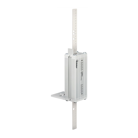
Page 9: Assembling Of The Encoder
Initially connect fastening angle and encoder with the connecting screw. For further improvements do not tighten the screw. Fig. 2: Pay attention to the right position which depends on the already installed measurement tape. EN - page 9 (Ants LEB01, R67911.0002 3) - Page 10 Fig. 3: Put the band into the encoder through the lateral opening. Check the right orientation of the holes with the aid of the marking on the encoder. Fig. 4: Push the sliding jaw with the designated tapekerf into the lateral opening. EN - page 10 (Ants LEB01, R67911.0002 3)
- Page 11 Fig. 5: Insert the aluminum rail from top to bottom as far as it can go into the allocated insertion slide-in. Fig. 6: Put the fastening angle on the car roof and re-adjust, if necessary. EN - page 11 (Ants LEB01, R67911.0002 3)
- Page 12 Fig. 7: Screw the fastening angle and retighten the connecting screw. EN - page 12 (Ants LEB01, R67911.0002 3)
-
Page 13: Direction Of The Band
A slight curvature of the measurement tape has no impact on the result, attention only has to be paid on the aluminum rail which has to be inserted from top to bottom. EN - page 13 (Ants LEB01, R67911.0002 3) - Page 14 In addition, the tape must be fed straight through the encoder in order to prevent premature wear of the sliding jaws. Incorrect assembly can have a negative effect on the service life or lead to malfunctions or failure of the measuring system. EN - page 14 (Ants LEB01, R67911.0002 3)
-
Page 15: Ssi
6.3 Protocol description One single position data needs to be pulled out by the SSI Master through 52 clocks: 1-25: MSB first absolut position in Graycode, data low (PFB), 27-51: second transmission (same as 1-25), data low (PFB) For costumer specific adjustments please contact the manufacturer. EN - page 15 (Ants LEB01, R67911.0002 3) -
Page 16: Canopen Lift (Ds-417)
ID HEX DATA_HEX Operational PRE-Operational STOP-Modus 7.4 Programming When programming, there must always be a band in the sensor. 7.4.1 Layer Setting Services (LSS) The Ants LEB01 has to be put into STOP mode. Change into LSS configuration mode: Master Slave: ID HEX DATA_HEX LSS-Mode EN - page 16 (Ants LEB01, R67911.0002 3) -
Page 17: Setting Baud Rate
7.4.2 Setting baud rate The Ants LEB01 has to be put into pre-operational mode or operational mode. Master Slave: ID HEX DATA_HEX new baudrate XX = 1->800kB2->500kBit, 3->250kBit, 4->125kBit, 6->50kBit,7->20kBit Slave Master: ID HEX DATA_HEX new baudrate ok For storage and changes please follow instructions in „LSS-Save“. -
Page 18: Permanent Data Storage
DATA_HEX 580+NodeID 500ms ok 7.4.7 Setting position-interval To receive position data, the Ants LEB01 has to be put into operational mode. The Ants LEB01 has to be put into pre-operational mode or operational mode. Master Slave: ID HEX DATA_HEX... -
Page 19: Electric Installation
Please note the respective wiring diagram depending on the model. Please note further that our product is already equipped with a terminating resistor. 9. Maintenance Generally the Ants LEB01 does not demand high maintenance requirements. In the course of routine servicing, proceed as follows: • Make sure the band is correctly directed between the sliding jaws (see “Direction of the band”) -
Page 20: Disposal And Recycling
5 m/s Connection: Cable 5 m, open end Operating temperature: -5°C ... +70°C Storage temperature: -10°C ... +70°C Supply voltage: 10 ... 30 VDC +/- 10% Interfaces: CANopen Lift, SSI, further on request EN - page 20 (Ants LEB01, R67911.0002 3) - Page 21 EN - page 21 (Ants LEB01, R67911.0002 3)
- Page 22 Kübler Group Fritz Kübler GmbH Schubertstr. 47 78054 Villingen-Schwenningen Germany Phone: +49 7720 3903-0 Fax: +49 7720 21564 info@kuebler.com www.kuebler.com...
Need help?
Do you have a question about the Ants LEB01 and is the answer not in the manual?
Questions and answers