
Subscribe to Our Youtube Channel
Related Manuals for Magnetrol STI Kotron 822


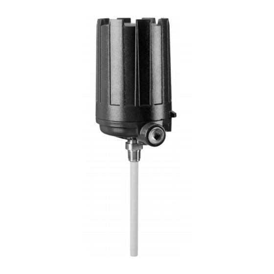
Summary of Contents for Magnetrol STI Kotron 822
- Page 1 Kotron Sentinel ® Models 822, 832 and 842 Software Ver. 2.0D Integral Mount Software Ver. 2.0C Remote Mount Installation and Operating Manual Capacitance Point Level Switches...
- Page 2 Notes do not normally contain described in this manual at any time without notice. actions. They follow the procedural steps to which Magnetrol makes no warranty with respect to the accuracy they refer. of the information in this manual.
-
Page 3: Table Of Contents
Kotron Sentinel Models 822, 832 and 842 RF Point Level Switches Table of Contents 1.0 Complete Installation 2.4 Calibration – Multi Point........16 1.1 Unpacking ............1 2.4.1 Program Path 1 – Configuration ....16 1.2 Electrostatic Discharge (ESD) Handling Procedure...1 2.4.2 Program Path 3 – Probe Calibration..17 1.3 Before You Begin ...........2 2.4.2.1 Probe Calibration Tips.......18 1.3.1 Site Preparation ..........2... -
Page 4: Complete Installation
• Record the model and serial numbers for future reference when ordering parts. Electrostatic Discharge (ESD) Handling Procedure Magnetrol’s electronic instruments are manufactured to the highest quality standards. These instruments use electronic components that may be damaged by static electricity pre- sent in most work environments. -
Page 5: Before You Begin
Before You Begin 1.3.1 Site Preparation Each Kotron Model 822, 832 and 842 switch is built to match the specific physical specifications of the required installation. Make sure the probe connection is correct for the threaded or flanged mounting on the vessel or tank where the switch will be placed. -
Page 6: Mounting
Mounting The Model 822, 832 or 842 switch can be mounted to a tank using a variety of process connections. Generally, either a threaded or flanged connection is used. For infor- mation about the sizes and types of connections available, see Probe Brochure 50-125. -
Page 7: Horizontal Mounting
1.4.1 Horizontal Mounting Alarm (narrow differential) applications only Horizontally mounted probes provide a high degree of sen- sitivity for use with non-conductive liquids as only approx- imately 0.5 inches (12 mm) of level change is required to completely cover (or uncover) the probe. Figure 1 Recommended Horizontal Mounting Horizontally mounted probes should be installed so that... -
Page 8: Probe Installation
The end of a flexible probe MUST be kept taut by attaching the anchor end at the bottom of the vessel or by using a Magnetrol supplied probe weight. Caution: Do not discard the Mylar ®... - Page 9 To install a probe: 1. Attach the weight or anchor assembly to the end of the probe. Insert the probe through the vessel’s mounting connection, and feed the cable into the CLAMP vessel. Do not allow the probe to scrape against the SET SCREW connection threads.
-
Page 10: Installing A Remote Unit
Installing a Remote Unit NOTE: Units with remote electronics are provided with the Main Amplifier and a preamplifier. Probe connections are made to the preamplifier. Refer to Section 1.5, Probe Installation for details in installing the probe. 3871 1.6.1 Main Amplifier Remote amplifier assemblies are normally shipped from + (Red) –... -
Page 11: Wiring
Wiring WARNING! Explosion hazard. Do not disconnect equipment unless power has been switched off or the area is known to be safe. 1.7.1 Relay Wiring The recommended connection of power and control circuits is 16 AWG or 18 AWG stranded wire. To improve external noise immunity, electrical snubbers are provided on the relay contacts. -
Page 12: Relay Wiring Chart
5. Replace housing cover. 6. Apply power to the unit, and proceed with calibration of instrument as described in Section 2.0, Calibration beginning on page 10. NOTE: Be certain to route all power and control wires through conduit outlet only and run probe wire up through center hole in ampli- fier housing base. -
Page 13: Calibration
The keys and their functions are shown below. Upon power up, the LED will display the following mes- sage: Magnetrol Int’l followed by a series of walk- ing M’s (multi-point) or S’s (single point), based on the calibration configuration selected. This is the normal RUN mode. -
Page 14: Program Paths
The microprocessor-based Sentinel offers all operator func- tions and setup procedures from the three tactile-feedback keys described above. Due to the number of user program- mable features included in the unit, the calibration flow chart is extensive. The flow chart is modular, however, it can be divided into five subsections or program paths which are connected to a home base, or normal operating mode, RUN (walking M or S). -
Page 15: Calibration-Single Point
Calibration—Single Point 2.3.1 Program Path 1 — Configuration The SING (single point) program is for single point alarm applications and allows for proper calibration without level change. The MULT (multi-point) program is for all pump (wide differential) control, multiple relay applications, and single point applications where an adjustable set point is needed. -
Page 16: Program Path 2 - Single Point
2.3.2 Program Path 2 — Single Point The single point program is for single point, alarm only applications and allows for proper calibration without level change. The following procedures must be followed if SING (single point) has been selected in Program Path 1 CNFG (configuration). - Page 17 3. If not, using the arrow keys, toggle DOWN between the INS (insulated) and the BARE (bare) probe selections. 4. When the appropriate selection is displayed, press to store the value and to display TDLO. NOTE: Choice of MDIA/COND and PRBE/BARE disarms the shorted probe diagnostic check.
- Page 18 FALT STEP 7: (Fault) 1. FALT (fault) refers to the choice of the alarm relay to DNRG (de-energize) or IGNR (ignore) upon diagnosing a fault. FALT STEP 7 DNRG NOTE: The dedicated diagnostic Relay 1 will always de-energize IGNR when a fault is detected. When FALT is displayed, press to display DNRG.
-
Page 19: Calibration-Multi Point
Calibration—Multi Point 2.4.1 Program Path 1 — Configuration The SING (single point) program is for single point alarm applications and allows for proper calibration without level change. The MULT (multi-point) program is for all pump (wide differential) control, multiple relay applications, and single point applications where an adjustable set point is needed. -
Page 20: Program Path 3 - Probe Calibration
2.4.2 Program Path 3 — Probe Calibration NOTES: 1. The media level must be moved to accomplish this procedure. The PRLO and PRHI points may be entered in any order; they can easily be changed in the future when the process level is at a much higher or lower point. -
Page 21: Probe Calibration Tips
The display will read PRLO once again. 6. Press the arrow key to leave the CAL mode and return to the RUN mode, MAGNETROL INTL M M M. Probe calibration is complete. Proceed to Section 2.4.3, Program Path 4 — Multi-Point. -
Page 22: Error Messages In Prlo/Hi Menus
5. Return to CNFG and repeat the above procedure now choose MULT from the MODE menu. Press . Unit reads MAGNETROL INTL M M M…. 6. All of the original data has now been cleared. 7. Begin Probe Calibration procedure again from the start of Program Path 3 (page 17). -
Page 23: Program Path 4 - Multi-Point
2.4.3 Program Path 4 — Multi-Point The following procedure must be follower if MULT (multi-point) has been selected in Program Path 1 CNFG (configuration). Probe calibration, Program Path 2, must also be accomplished for the Multi-Point program to operate. These two procedures, Multi-Point and Probe DISP XXXX Calibration, can be done in any order. - Page 24 RLY1 STEP 3: (Relay 1) 1. With displayed, press to display FALT. In RLY1 this setting, the RLY1 is used as a dedicated, diagnostic alarm. No other relay parameters (i.e., LVLO, TDHI) are offered. The relay will now de-energize when a diagnostic problem is encountered.
-
Page 25: Program Path 5 - Service
The Service program path is designed to aid the customer in troubleshooting the Sentinel; it should be accessed only with the assistance from Magnetrol factory personnel. Only the TEST mode section may be utilized without SERV factory assistance. - Page 26 STEP 3: (Hexadecimal) Press . Display will show a hexadecimal number related to capacitance in 0.25 pF increments. to exit HEX and return to SRVC. Press Press again to display VERS. Using the arrow key, press two times to DOWN display AVG.
-
Page 27: Advanced Calibration
Advanced Calibration Use these procedures in conjunction with standard calibra- tion procedures already observed. 2.5.1 Calibration with No Level Change 1. Single Point: Accomplished in Section 2.3.2, Program Path 2 — Single Point procedure. 2.5.2 Tank Commissioning Initial calibration in water (conductive medium) with final use in a non-conducive medium. -
Page 28: Reference Information
The LED display defaults to Noise from relay (and related equipment) Install filtering device 9i.e., MOVs) across Magnetrol Intl when a relay trips. is causing problems with microprocessor. relay terminals and supply voltage input. The S or M stops walking across LED The 8-pin header between the two circuit Consult factory. -
Page 29: Specifications
Specifications 3.2.1 Electrical Supply voltage 120 VAC, 50/60 Hz (+10/-15%) 240 VAC, 50/60 Hz (+10/-15%) 24 VDC (±10%) Power consumption 15 VA nominal Humidity 99% non-condensing (electronics) Electrostatic discharge protection Per IEC specification 801-2 Response time 70 ms to approximately 2 seconds, depending upon probe capacitance and averaging value Ambient temperature -40°... -
Page 30: Agency Approvals
Agency Approvals Agency Approved Model Protection Method Area Classification Class I Div. 1, Groups C & D 8X2-1X02-G0X Explosion proof 8X2-1X03-G0X Class II Div. 1, Groups E, F & G with rigid insulated probe NEMA 4X, IP65 8X2-1X05-G0X Explosion proof Electronics: Class I Div. -
Page 31: Intrinsic Safety
Intrinsic Safety 50-621 Kotron Sentinel Models 822, 832 and 842 RF Point Level Switches... - Page 32 Intrinsic Safety (cont.) Amplifier Amplifier Potted Potted intrinsically safe intrinsically safe module module Potted preamplifier module – Terminal + Terminal + Terminal – Terminal To Remote – Pre-amplifier + Front View Front View Power Amplifier supply/relays Power Amplifier supply/relays Potted intrinsically safe Potted module...
-
Page 33: Specifications
Specifications 3.5.1 Dimensional inches (mm) 4.63 (118) Dia. Rotation Rotation clearance 3.00 clearance (76) 2.75 (70) 3.75 3/4" NPT (95) Optional 4.11 mounting plugged (104) flange plugged 2.37 (60) 2 Holes .38 (10) Dia. 3.00 2.00 (76) (51) 1/2" NPT or 3/4"... - Page 34 inches (mm) Rotation Rotation clearance clearance .50 (13) .50 (13) .625 (16) .625 (16) Figure 20 Figure 21 Integral Mount with Standard Rigid Probe Integral Mount with Flexible Probe (shown with Carbon Steel Housing) (shown with Cast Iron Housing) 4.63 (118) Dia.
- Page 35 Ž Probe/amplifier connecting cable to be shielded, twisted-pair, 22-gauge NEMA 4X/7/9 1" NPT stranded conductors. Magnetrol P/N 009-7146-001 2500 feet (760 m); max- Dual conduit imum 800 feet (240 m) maximum for intrinsically safe models. 50-621 Kotron Sentinel Models 822, 832 and 842 RF Point Level Switches...
-
Page 36: Parts
Parts 3.6.1 Replacement Description Part Number Non-hazardous Z30-2409-001 Integral Hazardous Z30-2409-001 Amplifier I.S. circuitry Z30-2410-001 Non-hazardous Z30-2410-002 PC board Remote Hazardous Z30-2410-002 I.S. circuitry Z30-2410-001 Note: Refer to model number digit 7 for proper amplifier PC board Power supply/relay board: Model 822 Model 832 Model 842... -
Page 37: Model Numbers
Model Numbers RELAYS Relays 3 Relays (lead/lag) 4 Relays (lead/lag) INPUT POWER 120 VAC 240 VAC 24 VDC MOUNTING Integral NEMA 4X Remote NEMA 4X Integral NEMA 4X/7/9 Remote NEMA 4X/7/9 Integral NEMA 4X/7/9 w/intrinsically safe probe circuit Remote NEMA 4X/7/9 w/intrinsically safe probe circuit HOUSINGS NEMA 4X, aluminum base with carbon steel cover, ⁄... - Page 38 NOTES 50-621 Kotron Sentinel Models 822, 832 and 842 RF Point Level Switches...
- Page 39 NOTES 50-621 Kotron Sentinel Models 822, 832 and 842 RF Point Level Switches...
- Page 40 No claims for misapplication, labor, direct or consequen- tial damage will be allowed. 5300 Belmont Road • Downers Grove, Illinois 60515-4499 • 630-969-4000 • Fax 630-969-9489 • www.magnetrol.com 145 Jardin Drive, Units 1 & 2 • Concord, Ontario Canada L4K 1X7 • 905-738-9600 • Fax 905-738-1306 Heikensstraat 6 •...
Need help?
Do you have a question about the STI Kotron 822 and is the answer not in the manual?
Questions and answers