Sign In
Upload
Download
Table of Contents
Contents
Add to my manuals
Delete from my manuals
Share
URL of this page:
HTML Link:
Bookmark this page
Add
Manual will be automatically added to "My Manuals"
Print this page
×
Bookmark added
×
Added to my manuals
Manuals
Brands
Magnetrol Manuals
Switch
TD1 Series
Installation and operating manual
Magnetrol TD1 Series Installation And Operating Manual
Thermal dispersion flow/level/interface switch
Hide thumbs
1
2
Table Of Contents
3
4
5
6
7
8
9
10
11
12
13
14
15
16
17
18
19
20
21
22
23
24
25
26
27
28
29
30
31
32
page
of
32
Go
/
32
Contents
Table of Contents
Troubleshooting
Bookmarks
Table of Contents
Table of Contents
1 Installation
Unpacking
Electrostatic Discharge (ESD) Handling Procedure
Mounting
Wiring
Relay Connections
Remote Electronics Wiring (TD2 Only)
Ma Output Wiring (TD2 Only)
Setup
Switch Settings
LED Operation
LED Initialization
Time Delay (TD2 Only)
Calibration
Adjustment Procedure for LEVEL Applications
Unable to Change Level
Low Flow/No Flow
Adjustment Procedure for HIGH FLOW Detection
Unable to Change Flow Rate
Advanced Calibration Procedure (TD2)
Quick Start
3 Reference Information
Description
Theory of Operation
Fault Detection
Resistance Values
Troubleshooting
Maintenance
Cleaning
Probe Replacement
Integral Electronics
Remote Electronics (TD2)
Agency Approvals
Replacement Parts
Model TD1
Model TD2
Specifications
Performance
Probe
Physical
Model Numbers
Model TD1
Model TD2
Standard Probe
High Temperature Probe
Low Flow Body
Mini Sensor
Connecting Cable
Advertisement
Quick Links
1
Wiring
2
Switch Settings
3
Calibration
4
Model Td2
Download this manual
Installation and Operating Manual
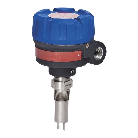
Model TD1
with twin-tip probe
Model TD2
with spherical probe
with low flow body
Thermatel
Model TD1/TD2
Thermal Dispersion
Flow/Level/Interface
Switch
Model TD2
®
Table of
Contents
Previous
Page
Next
Page
1
2
3
4
5
Advertisement
Table of Contents
Need help?
Do you have a question about the TD1 Series and is the answer not in the manual?
Ask a question
Questions and answers
Related Manuals for Magnetrol TD1 Series
Switch Magnetrol T20 Installation And Operating Manual
Liquid level switches (24 pages)
Switch Magnetrol T20 Instruction Manual And Replacement Parts List
Top mounting liquid level switches (12 pages)
Switch Magnetrol Thermatel TD1 Installation And Operating Manual
Thermal dispersion flow, level, interface switch (28 pages)
Switch Magnetrol Thermatel TD1 Installation And Operating Manual
Thermal dispersion flow/level/interface switch (32 pages)
Switch Magnetrol TK1 Operating Manual
Side-mounted liquid level float switch (13 pages)
Switch Magnetrol TD2 Series Installation And Operating Manual
Thermal dispersion flow/level/interface switch (32 pages)
Switch Magnetrol TD2-0 Series Installation And Operating Manual
Thermal dispersion flow/level/interface switch (32 pages)
Switch Magnetrol Thermatel TD2 Installation And Operating Manual
Thermal dispersion flow/level/interface switch (32 pages)
Switch Magnetrol AMETEK T62 Installation And Operating Manual
Liquid level switches (17 pages)
Switch Magnetrol Echotel 910 Installation And Operating Manual
Ultrasonic liquid level switches (12 pages)
Switch Magnetrol F10 Instruction Manual And Parts List
Vane type flow switches (9 pages)
Switch Magnetrol C29 Installation And Operating Manual
Float actuated liquid level switches (24 pages)
Switch Magnetrol Echotel 961 Installation And Operating Manual
Ultrasonic single and dual point level switches (17 pages)
Switch Magnetrol Echotel 961 Installation And Operating Manual
Loop powered ultrasonic single and dual point level switches (13 pages)
Switch Magnetrol ECHOTEL 910 Installation And Operating Manual
(8 pages)
Switch Magnetrol ECHOTEL 940 Installation And Operating Manual
(9 pages)
This manual is also suitable for:
Td2 series
Td2-0 series
Td2-h0 series
Td2-d0 series
T-d-c series
T-h-c series
...
Show all
Td2-d0-c series
Td1-2d00-0 series
Table of Contents
Print
Rename the bookmark
Delete bookmark?
Delete from my manuals?
Login
Sign In
OR
Sign in with Facebook
Sign in with Google
Upload manual
Upload from disk
Upload from URL


Need help?
Do you have a question about the TD1 Series and is the answer not in the manual?
Questions and answers