Table of Contents
Advertisement
Advertisement
Table of Contents

Related Manuals for Magnetrol T20


Summary of Contents for Magnetrol T20
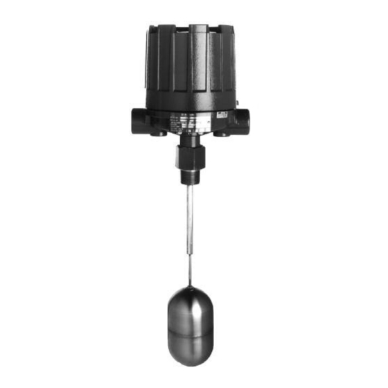
- Page 1 Top Mounting T20 and T21 Installation and Operating Manual iquid evel Switches...
- Page 2 MAGNETROL will repair or replace the control at no may result in minor or moderate injury. cost to the purchaser (or owner) other than transportation.
-
Page 3: Table Of Contents
2.3 Mounting ..............5 5.3.1 Physical.............15 2.4 Wiring..............6 5.4 Replacement Parts ..........16 3.0 Switch Differential djustment ........8 5.4.1 Model T20 Parts Identification....16 5.4.1.1 Model T20........17 4.0 Preventive Maintenance 5.4.1.2 Mounting flanges ......17 4.1 What to do............10 5.4.1.3 Switch and housing reference ..17 4.1.1 Keep control clean ........10... -
Page 4: Introduction
Introduction T20 and T21 level switches are float operated units designed for top mounting to a tank or vessel by means of threaded or flanged pipe connections. T20 standard units are equipped with a single switch mechanism for high or low level alarm or control applications. -
Page 5: Critical Alarm Function
Caution: This instrument is intended for use in Installation Category II, Pollution Degree 2. Adjust the process connection as required to bring control to a vertical position. MAGNETROL controls must be mounted within three degrees of vertical in all directions. A three degree slant is noticeable by eye, but installation should be checked with a spirit level on top and/or sides of float stem or enclosing tube. -
Page 6: Wiring
Wiring Caution: All Top Mounting units are shipped from the factory with the enclosing tube tightened and the switch housing set screw locked to the enclosing tube. Failure to loosen the set screw prior to repositioning the supply and output connections may cause the enclosing tube to loosen, resulting in possible leakage of the process liquid or vapor. - Page 7 6. Dress wiring to ensure no interference or contact with the switch actuation arm, or replacement of switch housing cover. NOTE: Observe all applicable electrical codes and proper wiring procedures. Prevent moisture seepage into the enclosure by installing approved seal-drain fittings in the conduit run leading into the unit.
-
Page 8: Switch Differential Djustment
Switch Differential Adjustment The standard differential of the single float Model T20 may be field adjusted. Adjustment may be necessary if a wider differential needs to be set to overcome switch chatter caused by the process. The differential, or the amount of level travel between switch-on and switch-off, may be adjusted by reposition- ing the lower jam nuts on the float stem. - Page 9 7. With switch housing and enclosing tube removed, jam nuts and attraction sleeve are accessible. Measure position of upper jam nuts from stem end; then loosen and remove upper jam nuts, guide washer, and attraction sleeve. 8. Loosen and adjust lower jam nuts to desired position. Make certain jam nuts are retightened securely.
-
Page 10: Preventive Maintenance
Preventive Maintenance Periodic inspections are a necessary means to keep your level control in good working order. This control is a safe- ty device to protect the valuable equipment it serves. Therefore, a systematic program of “preventive mainte- nance” must be implemented when the control is placed into service. -
Page 11: Inspect Entire Unit Periodically
5. On units with pneumatic switches, air (or gas) lines sub- jected to vibration, may eventually crack or become loose at connections causing leakage. Check lines and connec- tions carefully and repair or replace, if necessary. NOTE: As a matter of good practice, spare switches should be kept on hand at all times. -
Page 12: Reference Information
Reference Information Troubleshooting Usually the first indication of improper operation is failure of the controlled equipment to function, (i.e.: pump will not start (or stop), signal lamps fail to light, etc.) When these symptoms occur, whether at time of installation or during routine service thereafter, check the following potential external causes first. -
Page 13: Check Complete Unit
5.1.2 Check complete unit 1. Reconnect power supply and carefully actuate switch mechanism manually (using a non-conductive tool) to determine whether controlled equipment will operate. Caution: With electrical power on, care should be taken to avoid contact with switch leads and connections at terminal block. -
Page 14: Agency Approvals
6. Check float to be certain it is buoyant in the liquid (tank or vessel must have adequate liquid level). If float is deter- mined to be filled with liquid, or it is collapsed, it must be replaced immediately. Do not attempt to repair a float. If all components in the control are in operating condition, the trouble must be (and should be) located external to the control. -
Page 15: Specifications
⁄ " NPT single entry Pneumatics (119) (127) (214) 10.12 ➀ All housings rotatable 360°. (257) ➁ Pneumatic switches available with Series T20 units only. 1.81 (45) Ref. Distance to upper actuating level (4" min.) Actuating level Distance To Maximum... -
Page 16: Replacement Parts
Replacement Parts 5.4.1 Model T20 Parts Identification Item Description Housing cover Housing base Switch mechanism Attraction sleeve Jam nuts Guide washer(s) Float stem Float Adaptor bushing/guide tube assembly Enclosing tube gasket Enclosing tube Mounting flange 44-604 Top Mounting Liquid Level Switches... -
Page 17: Model T20
5.4.1.1 Model T20 T20-1 T20-4 Housing cover See below Housing base See below Switch mechanism See below Stem kit: includes items 4, 5, 6, & 7 Consult factory Float: 3.00" ¥ 5.00" Z07-1202-003 3.50" ¥ 6.00" Z07-1202-009 4.00" Z07-1102-008 4.50"... -
Page 18: Model T21 Parts Identification
Replacement Parts 5.4.2 Model T21 Parts Identification Item Description Housing cover Housing base Switch mechanism Upper attraction sleeve Jam nuts Guide washer(s) Upper stem assembly Lower float Lower attraction sleeve, stop tube, and washers Retaining rings Upper float and tube assembly Adaptor bushing Enclosing tube gasket Enclosing tube... -
Page 19: Model T21
5.4.2.1 Model T21 T21-1 T21-4 Housing cover See below Housing base See below Switch mechanism See below Float stem kit: includes items 4, 5, 6, & 7 Consult factory Lower float: 3" ¥ 5" Z07-1201-003 Z07-1202-003 4.00" Z07-1101-015 Z07-1102-008 4.50" Z07-1102-009 Upper float and tube assembly kit: includes items 9, 10, &... -
Page 20: Model Numbers
(26) ➀ Flanges are ANSI standard threaded onto 1" NPT bushing. Forged steel flanges have standard raised face. ➁ Not available with Model T20-4. ➂ Available only in cast iron. ➃ Process temperature based on +100° F (+38° C) ambient. - Page 21 ELECTRIC SWITCH MECHANISM AND ENCLOSURE T20-1 Models T20-4 Models Process ➃ TYPE 4X/7/9 Aluminum Enclosure ➄≈ Temperature Switch Contacts Range Description ATEX ATEX Points Class I, Div 1 Class I, Div 1 Class I, Div 1 Class I, Div 1...
-
Page 22: Model T21
Model Numbers 5.5.2 Model T21 IMPORTANT: Actuating level(s), in either the rising or falling state, and specific gravity must be provided upon placement of order. MODEL NUMBER CODE AND MATERIALS OF CONSTRUCTION Model No. Set Points Tank Connection Float and Trim Sleeve T21-1 Carbon steel... - Page 23 ELECTRIC SWITCH MECHANISM AND ENCLOSURE Process ➃ T21-1 Models T21-4 Models TYPE 4X/7/9 Aluminum Enclosure ➄≈ Temperature Switch Contacts Range Description ATEX ATEX Points Class I, Div 1 Class I, Div 1 Class I, Div 1 Class I, Div 1 Ex II 2 G EEx Ex II 2 G EEx °F (°C)
- Page 24 705 Enterprise Street • Aurora, Illinois 60504-8149 • 630-969-4000 • Fax 630-969-9489 info@magnetrol.com • www.magnetrol.com Copyright © 2015 Magnetrol International, Incorporated. All rights reserved. Printed in the USA. BULLETIN: 44-604.17 EFFECTIVE: January 2015 Magnetrol and Magnetrol logotype are registered trademarks of Magnetrol International.
Need help?
Do you have a question about the T20 and is the answer not in the manual?
Questions and answers