
Subscribe to Our Youtube Channel
Related Manuals for Magnetrol Thermatel TD1


Summary of Contents for Magnetrol Thermatel TD1
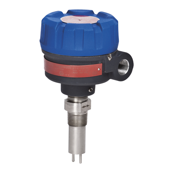
- Page 1 Thermatel ® Model TD1/TD2 Installation and Operating Manual Thermal ispersion Flow/Level/Interface Switch Model TD2 with spherical probe Model TD1 with twin-tip probe Model TD2 with low flow body...
- Page 2 MAGNETROL will repair or replace the control at no cost to the purchaser (or owner) other than transportation. W RNINGS...
-
Page 3: Table Of Contents
Thermatel Model T 1/T 2 ® Thermal ispersion Flow/Level Switch Table of ontents 1.0 Quick Start 3.7 Agency Approvals............20 2.0 Installation 3.7.1 Specific Conditions of Use......21 2.1 Unpacking ..............4 3.8 Replacement Parts...........22 2.2 Electrostatic Discharge (ESD) Handling Procedure...4 3.8.1 Model TD1 ..........22 2.3 Mounting..............5 3.8.2 Model TD2 ..........23 2.4 Wiring ..............6... -
Page 4: Quick Start
Report any discrepancies to the factory. Check and record the serial number for future reference when ordering parts. Serial Number Electrostatic Discharge (ESD) Handling Procedure Magnetrol electronic instruments are manufactured to ® the highest quality standards. These instruments utilize electronic components which may be damaged by static electricity present in most work environments. -
Page 5: Mounting
Flow orientation is marked on the wrench flats or on the top of the flange for reference. 3. For flow switches calibrated by MAGNETROL, install the Figure 3 probe near the centerline of the pipe. If not calibrated by... -
Page 6: Wiring
Wiring The wiring connections for the power and relay are suitable for 12–24 AWG wire. Caution: OBSERVE ALL APPLICABLE ELECTRICAL CODES AND PROPER WIRING PROCEDURES. 1. Make sure the power source is turned off. 2. Unscrew and remove housing cover. 3. -
Page 7: Relay Connections
2.4.1 Relay Connections TD1/TD2: DPDT 8 amp at 120–250 VAC 8 amp at 28.8 VDC, 0.5 amp at 125 VDC resistive The TD1 transmitter shall be connected to a safety extra low-voltage circuit (SELV) with a Um 28.8 V. TD2 with Hermetically sealed relay: DPDT 1 amp at 28 VDC, 0.2 amp at 125 VDC resistive The switch may be configured so that the relay either energizes or de-energizes when the set point is reached. -
Page 8: Remote Electronics Wiring (Td2 Only)
1 through 6. The cable shield should be connected to the TD2 Electronics green ground screw in the sensor housing. If the cable is supplied by MAGNETROL, then this connection is pre-wired at the circuit board. The user only needs to connect the wiring at the terminal connection on the sensor enclosure. -
Page 9: Setup
FAULT switch position of the TD2 is shown in Figure 10. ALARM The switch settings are set at MAGNETROL during setup. Changes in the positions may be required in the MODEL TD1 field depending upon the application. There is a tag wired Figure 9 onto the switch which indicates the default settings. -
Page 10: Led Operation
2.5.2 LED Operation TD1 – Two LEDs (Green & Red) • Green LED glows when power is on. • Red LED, glows when an alarm condition exists. The LED operation is independent of relay operation. • The red LED will blink rapidly if the switch detects a fault. It will blink slowly during initial power-on. -
Page 11: Calibration
Calibrating the switch in a different media may change the set point. If the device was factory calibrated by MAGNETROL, then there is no need to perform an additional calibration. NOTE: Set the switches (Section 2.5.1) to the desired position before performing the calibration. - Page 12 5a. High Level Applications a. Set fail-safe switch to the “HL” position (switch up High Level Adjustment b. Turn alarm potentiometer counterclockwise until red (High Level Fail-safe) LED turns on. c. Turn alarm potentiometer clockwise until red LED turns off. d.
-
Page 13: Unable To Change Level
2.6.1.1 Unable to Change Level Typical Switch Settings: • Low Level: Follow the procedures in Step 5b, steps a–e on (See page 9 for detail settings) page 12. Any change in media will cause a low level alarm indication. POWER •... -
Page 14: Adjustment Procedure For High Flow Detection
2.6.3 Adjustment Procedure – HIGH FLOW Detection 1. Place Fail-safe in the “HL” position ( 2. Increase the flow rate to desired alarm point. Allow 3 minutes for the sensor to stabilize. 3. Rotate alarm potentiometer counterclockwise until the red LED turns on. -
Page 15: Advanced Calibration Procedure (Td2)
Zone 0 service. 3.0 Reference Information Description THERMATEL TD1/TD2 switches are used for flow, level, and interface detection and control. Level detection is accomplished by sensing changes in the heat transfer char- acteristics of the media. Flow detection is accomplished by sensing changes in heat transfer caused by the flowing media. -
Page 16: Fault Detection
Each element of the sensor is a miniature RTD (Resistance Temperature Detector). One element measures the tem- perature of the process, providing a reference temperature. The second RTD is self-heated to establish a temperature differential above the reference temperature. The cooling effect on the heated RTD, caused by the presence of flow or level, decreases the differential temperature between the two RTDs. -
Page 17: Troubleshooting
Troubleshooting The TD1/TD2 switches have various settings to handle a wide variety of flow and level applications. If the switch is not performing properly, check the switch settings on page 9 or the following: Symptom Application Action Unable to adjust set point Air Flow Detection Ensure that the probe is extended into the flow to obtain alarm... -
Page 18: Maintenance
Maintenance 3.6.1 Cleaning The probe may be cleaned by soaking, spraying solvents or detergent and water onto the sensor tubes, or by ultrasonic cleaning. Lime deposits may be safely removed by soaking in 20% hydrochloric acid. Warming to +150 °F (+66 °C) is permissible to speed this process. -
Page 19: Remote Electronics (Td2)
Installation of replacement probe (Refer to Figures 15 & 16). 1. The probe’s leads have been separated at the factory. One set of leads is marked with a “1,” the second set is unmarked. Connect leads from RTD #1: TD1 – Connect between terminals 1 and 3. Unmarked Wires TD2 –... -
Page 20: Agency Approvals
Hastelloy C, Monel, or 1mm thick stainless steel.) Zone 1 Service TXX-XXXX-XGX Ex d Flame Proof BR-Ex d IIC T5/T4 IP66 TDX-XXXX-XCX Russian Authorisation Standards TDX-XXXX-XGX Consult MAGNETROL for details. CCOE TDX-XXXX-XCX Hazardous Approvals - India TDX-XXXX-XGX Consult MAGNETROL for details. TDX-XXXX-XCX Hazardous Approvals - Korea TDX-XXXX-XGX Consult MAGNETROL for details. -
Page 21: Specific Conditions Of Use
The following approval standards are applicable: FM3600:2018, FM3611:2018, FM3615:2018, FM3810:2018, ANSI/UL60079-0:2019, ANSI/UL 60079-1:2015, ANSI/UL 60079-11:2014, ANSI/UL 60079-26:2017, ANSI/UL 61010-1:2012, ANSI/ISA 60079-11:2014, ANSI/ISA 60079-26:2014, ANSI/NEMA 250:1991, ANSI/IEC 60529:2004, CSA-C22.2 No. 0.4:2017, CSA-C22.2 No. 0.5:2016, CSA-C22.2 No. 25:R2014, CSA-C22.2 No. 30:R2016, CSA- C22.2 No. 94:R2011, CSA-C22.2 No. 213:2016, CSA-C22.2 No. -
Page 22: Replacement Parts
Replacement Parts 3.8.1 Model TD1 Model TD1 Item Description Part Number 089-6607-XXX Aluminum Cover Consult Factory O-ring 012-2201-237 Electronic module with bracket 089-7250-001 Probe See Probe Model Number 54-610 Thermatel ® Model TD1/TD2 Flow Level Switch... -
Page 23: Model Td2
Remote (8th digit = 1) AC (4th digit = 7) 089-7250-010 089-7250-012 DC (4th digit = 8) 089-7250-011 089-7250-013 NOTE: Contact MAGNETROL for Modules for Hygienic Enclosure (digit 10 = 4 or 5). 54-610 Thermatel ® Model TD1/TD2 Flow Level Switch... -
Page 24: Specifications
3.9 Specifications 3.9.1 Performance Supply Voltage TD1 19.2 to 28.8 VDC TD2 19.2 to 28.8 VDC or 100 to 264 VAC , 50–60 Hz Power Consumption TD1: 3.5 Watts at 24 VDC 4.5 Watts at 28.8 VDC TD2: 4 Watts at 24 VDC 4.5 Watts at 28.8 VDC 5 Watts at 100 to 264 VAC Power to Probe... - Page 25 Pressure/Temperature Rating (DEPENDENT ON PROCESS CONNECTION) Process / Temperature Rating Probe Style Insertion Length +100 °F (+38 °C) +250 °F (+121 °C) +400 °F (+204 °C) +850 °F (+454 °C) 3000 psig 2460 psig 2140 psig 2" (5 cm) — (206 bar) (169 bar) (147 bar)
-
Page 26: Physical
3.9.3 Physical – inches (mm) 4.00 4.00 (102) (102) Without Window 4.13 4.43 (113) (105) With Window 4.85 (123) 1.8 (46) Typical 1.8 (46) Typical Insertion Insertion Insertion length length length BSP(G) Threads Threads .875 .875 (23) Dia. (23) Dia. Model TD1 Model TD2 Integral Electronics with Twin Tip Probe... -
Page 27: Model Numbers
3.10 Model Numbers 3.10.1 Model TD1 AGENCY APPROVAL General Purpose, FM/CSA Explosion Proof ATEX/IECEx Ex d + ib, Zone 0 – Flameproof ENCLOSURE TYPE Aluminum A356 – ⁄ " NPT Aluminum A356 – M20 3.10.2 Model TD2 POWER AC Power DC Power RELAY OUTPUT DPDT Relay... -
Page 28: Standard Probe
3.10.3 Standard Probe MODEL Probe length in inches Probe length in centimeters TIP STYLE ➀ ➀ Available only with stainless Spherical tip max. +250 °F (+121 °C) ➀ steel construction Spherical tip – with 6" (15 cm) heat extension max. +400 °F (+204 °C) Twin tip max. -
Page 29: High Temperature Probe
3.10.4 High Temperature Probe MODEL Probe length in inches Probe length in centimeters TIP STYLE High temperature/high pressure twin tip max. +850 °F (+450 °C)/max. 6000 psi (413 bar) MATERIAL OF CONSTRUCTION 316/316L stainless steel Hastelloy ® 316/316L stainless steel with 1 mm probe thickness (Available only with TMH probes) Hastelloy C, NACE 316/316L stainless steel, ASME B31.3 (CRN Available) 316/316L stainless steel, ASME B31.3 and NACE (CRN Available) -
Page 30: Low Flow Body
3.10.5 Low Flow Body MODEL Low Flow Body MATERIAL OF CONSTRUCTION 316/316L stainless steel PROCESS CONNECTION SIZE/TYPE ⁄ " NPT Thread (CRN Available) ⁄ " NPT Thread (CRN Available) ⁄ ⁄ " BSP) Thread ⁄ ⁄ " BSP) Thread SENSITVITY Standard High Sensitivity ➀... -
Page 31: Connecting Cable
3.10.7 Connecting Cable (General Purpose, FM/CSA) CONNECTING CABLE IN FEET 10 feet minimum to 500 feet maximum length Example: 12 feet = code 012 CONNECTING CABLE IN METERS 3 meters minimum to 152 meters maximum length Example: 3 meters = code 003 54-610 Thermatel ®... - Page 32 705 Enterprise Street • Aurora, Illinois 60504-8149 • 630.969.4000 info@magnetrol.com • magnetrol.com Copyright © 2020 Magnetrol International, Incorporated Magnetrol, Magnetrol logotype and Thermatel are registered trademarks of Magnetrol International, Incorporated. CS logotype is a registered trademark of Canadian Standards ssociation. BULLETIN: 54-610.12 Hastelloy®...
Need help?
Do you have a question about the Thermatel TD1 and is the answer not in the manual?
Questions and answers