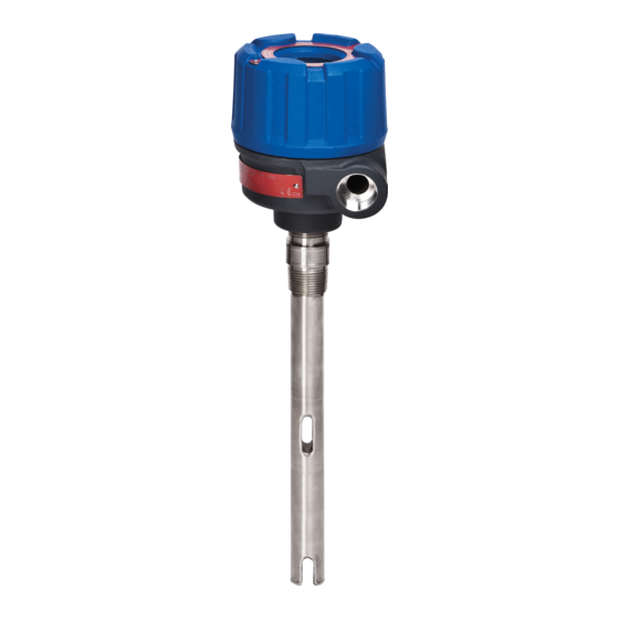
Magnetrol Echotel 961 Installation And Operating Manual
Ultrasonic
single and
dual point
level switches
Hide thumbs
Also See for Echotel 961:
- Installation and operating manual (17 pages) ,
- Functional safety manual (16 pages) ,
- Sil safety manual (24 pages)

Subscribe to Our Youtube Channel
Related Manuals for Magnetrol Echotel 961


Summary of Contents for Magnetrol Echotel 961
- Page 1 Model 961/962 Installation and Operating Manual Ultrasonic Single and Dual Point Level Switches Model 961 Model 962...
- Page 2 In this manual, a warning indicates MAGNETROL will repair or replace the control at no an imminently hazardous situation which, if not cost to the purchaser (or owner) other than transportation.
-
Page 3: Table Of Contents
Echotel Model 961 & 962 ® Ultrasonic Single and Dual Point Liquid Level Switches Table of Contents 1.0 Introduction ..............4 2.5.3.3 Malfunction Test Push Button ....17 1.1 Principle of Operation ..........4 2.5.3.4 High/Low DIP Switch ......18 2.0 Installation ..............4 2.5.3.5 PC/LC DIP Switch .......18 2.1 Unpacking ..............4 2.5.3.6 LC and Hi/Lo DIP Switch Configuration 18 2.2 ESD Handling Procedure..........5... -
Page 4: Introduction
Introduction ECHOTEL Model 961 and 962 ultrasonic level switches utilize pulsed signal technology to detect high, low, or dual point level in a broad range of liquid media applications. Model 961 is a single point level switch. Model 962 is a dual point switch used as a level controller or to control pumps in an auto-fill or auto-empty mode. -
Page 5: Esd Handling Procedure
Electrostatic Discharge (ESD) Handling Procedure MAGNETROL electronic instruments are manufactured to the highest quality standards. These instruments use electronic components that may be damaged by static electricity present in most work environments. The following steps are recommended to reduce the risk of component failure due to electrostatic discharge. -
Page 6: Wiring
Wiring Wiring for Model 961/962 level switches is different for all four versions. These switches are available as 4-wire, line- powered units with 5-amp relays, or as 2-wire loop-pow- ered units with mA current shift output. Determine which version you have from the table below and proceed to the proper wiring section. -
Page 7: Model 961 Remote Transducer Housing Wiring
2.4.1.1 Model 961 Remote Transducer Housing Wiring Remote mount Model 961 units have a “1” as the 8th digit (961-XXXX-1XX) of the model number. The 037-3316-XXX cabling is connected at the factory on the electronics end, and secured with a cable tie. The other end of the cabling is connected by the user inside the remote transducer housing at a terminal block marked as 1 2 3 4 on a blue label. -
Page 8: Model 961 Loop-Powered Wiring
2.4.2 Model 961 Loop-powered Wiring For intrinsically safe installations, refer to the Agency Drawing in Section 3.6.1. Loop wiring connections are suitable for 12–24 AWG wire. Caution: OBSERVE ALL APPLICABLE ELECTRICAL CODES AND PROPER WIRING PROCEDURES. MODEL 961 TIME 1. Make sure the power source is turned off. DELAY FAULT LOOP... -
Page 9: Model 962 Line-Powered Wiring
Ground FORCE FORCE FAULT CHANGE Shield: 1, 3 Signal: 2, 4 037-3316-xxx Cabling Electronics Module Remote Transducer Housing Figure 9 Model 961 Loop-Powered Remote Transducer Wiring 2.4.3 Model 962 Line-powered Wiring Power and relay wiring connections are suitable for 12– Lower Gap Upper Gap SPDT Relay... -
Page 10: Model 962 Remote Transducer Housing Wiring
2.4.3.1 Model 962 Remote Transducer Housing Wiring Remote mount Model 962 units have a “1” in the 8th digit (962-XXXX-1XX) of the model number. The 037-3317-XXX cabling is connected at the factory on the electronics end, and secured with a cable tie. The other end of the cabling is connected by the user inside the remote transducer housing at terminal blocks marked as 1 2 3 4 5 6 7 8 on a blue label. -
Page 11: Model 962 Loop-Powered Wiring
2.4.4 Model 962 Loop-powered Wiring For intrinsically safe installations, refer to the Agency Drawing in Section 3.6.1. Loop wiring connections are suitable for 12–24 AWG wire. Caution: OBSERVE ALL APPLICABLE ELECTRICAL CODES AND PROPER WIRING PROCEDURES. MODEL 962 1. Make sure the power source is turned off. TIME DELAY FAULT... -
Page 12: Configuration
Ground Shield: 1, 3, 5, 7 Signal: 2, 4, 6, 8 037-3317-xxx Cabling Model 962 Remote Transducer Wiring Figure 13 Model 962 Loop-Powered Remote Transducer Wiring Model 962 Loop-powered Remote Mount Wiring Transducer Electronics Transducer Cable Wire Housing TB Housing TB & Marker Marker Position... -
Page 13: Time Delay Potentiometer
2.5.1.1 Time Delay Potentiometer The time delay potentiometer is typically used in applica- tions where turbulence or splashing may cause false level alarms. This is a 25-turn pot with a factory default setting of 0.5 seconds. If desired, this pot may be turned clockwise to increase the response time from the standard 0.5 seconds to a maximum of 10 seconds. -
Page 14: High/Low Dip Switch
2.5.1.4 High/Low DIP Switch i/Lo Dip Switch is used to select whether the Model 961 will be used as a high level fail-safe (HLFS) switch or a low level fail-safe (LLFS) switch. In the i position the DPDT process level relay will de-energize (alarm condition) when the gap becomes wet. -
Page 15: Model 961 Loop-Powered Configuration
2.5.2 Model 961 Loop-powered Configuration Model 961 loop-powered units have the following config- uration options: • TIME DELAY potentiometer for 0.5 to 10 second signal averaging • LOOP TEST push button for testing the 8/16 mA loop MODEL 961 TIME output DELAY FAULT... -
Page 16: High/Low Dip Switch
2.5.2.4 High/Low DIP Switch The Hi/Lo DIP switch is used to select whether the 961 will be used as high level fail-safe switch or low level fail-safe switch. Normal process level operation produces an 8 mA value, and 16 mA is produced when the unit is in a level alarm state. -
Page 17: Model 962 Line-Powered Configuration
2.5.3 Model 962 Line-powered Configuration Model 962 line-powered units have the following configu- ration options: • TIME DELAY potentiometer for 0.5 to 10 second signal averaging • LEVEL TEST push button for testing of the SPDT process level relays MALF RELAY LOWER UPPER TIME... -
Page 18: High/Low Dip Switch
2.5.3.4 High/Low DIP Switch The Hi/Lo DIP switch is used to select whether the 962 will be used as a high level fail-safe (HLFS) switch or low level fail-safe (LLFS) switch. The setting of the Hi/Lo DIP also affects how the PC/LC DIP switch configures the unit. -
Page 19: Pc And Hi/Lo Dip Switch Configuration
2.5.3.7 PC and Hi/Lo DIP Switch Configuration Tables Pump Control (DIP switch set to PC) Auto-empty Pump Control Sequence Lower Gap Upper Gap Level Hi/Lo DIP Condition Switch Relay Relay energized energized energized energized de-energized de-energized de-energized de-energized energized energized NOTE: During a fault condition all three relays de-energize Pump Control (DIP switch set to PC) Auto-fill Pump Control Sequence... -
Page 20: Model 962 Loop-Powered Configuration
2.5.4 Model 962 Loop-powered Configuration Model 962 loop-powered units have the following config- uration options: • TIME DELAY potentiometer for 0.5 to 10 second signal MODEL 962 averaging TIME DELAY FAULT LOOP • LOOP TEST push button for testing the 8/12/16 mA TEST TEST Hi 22... -
Page 21: High/Low Dip Switch
2.5.4.4 High/Low DIP Switch The Hi/Lo DIP switch is used to select whether the 962 will be used as high level fail-safe switch or low level fail- safe switch. Normal process level operation produces an 8 mA value, and 16 mA is produced when the unit is in a level alarm state. -
Page 22: Reference Information
Reference Information Electronics Specifications 3.1.1 Model 961/962 with Relay Output Supply Voltage 12 to 35 VDC, or 100 to 265 VAC, 50/60 Hz Relay Outputs 961: One DPDT level relay and one SPDT malfunction relay 962: Two SPDT level relays and one SPDT malfunction relay Relay Ratings DPDT: 5 amps @ 120 VAC, 250 VAC, and 30 VDC, 0.15 amp @ 125 VDC... -
Page 23: Physical Specifications
hysical Specifications Housing Material Cast aluminum 356-T6, or cast 316 stainless steel Cable Entry ⁄ " NPT, or M20 Gross Weight 961/962 Electronics: 2.2 lbs. (1.0 kg) 2" (5 cm) Transducer: 0.6 lbs. (0.3 kg) Transducer Specifications 3.4.1 Model 9A1/9M1 Single Point Maximum Pressure ¡... -
Page 24: Dimensional Specifications
Dimensional Specifications Inches (mm) 4.00 5.24 (102) (133) 4.00 (102) 4.43 (113) 5.75 4.43 (113) (146) 2.35 (60) Typical 1.05 (26) 1.8 (46) Typical Typical Actuation length Actuation length Actuation length for Tri-Clamp fitting for ANSI flange for NPT connection 0.25 (6) 0.25 (6) 0.25 (6) - Page 25 Dimensional Specifications Inches (mm) 4.00 (102) 4.00 (102) 3.95 (100) 4.43 (113) 1.8 (46) Typical 2.75 2 Holes (70) .38 (10) dia. Actuation length for NPT connection 3.00 2.00 (76) (51) 0.25 (6) 3.50 (89) ∅ .875 (22) Model 961/962 with Remote Electronics Remote Transducer with NPT Connection 4.00...
-
Page 26: Agency Approvals
gency pprovals AGENCY APPROVED MODELS PROTECTION METHOD AREA CLASSIFICATION FM & CSA 96X-X0A0-X10 Explosion Proof Class I, Div. 1,Groups B, C, & D 96X-X0A0-X11 Class II, Div. 1, Groups E, F, & G 96X-X0A0-X12 Class III, Type 4X, IP 66, T6 96X-X0A0-X13 96X-X0A1-X10 96X-X0A1-X11... -
Page 27: Agency (Fm/Csa) Drawing And Entity Parameters
3.6.1 Agency (FM/CSA) Drawing and Entity Parameters 51-646 chotel ® Model 961 & 962 Ultrasonic Level Switches... -
Page 28: Troubleshooting
3.7 Troubleshooting Caution: In hazardous areas, do not remove the housing cover until power is disconnected and the atmosphere is determined to be safe. The Model 961/962 has a unique diagnostics feature to assist in troubleshooting should a failure occur. A micro- processor in the electronics continuously monitors all self- test data. - Page 29 Two flashes of the LED indicates an issue with the elec- tronics module. Contact the factory for a replacement electronics module. See Section 3.8 for spare electronics module part numbers. Environmental noise is the issue if the diagnostic LED flashes three times. Common sources of environmental noise are conducted electrical noise from a VFD (variable frequency drive), radiated electrical interference from a two-way radio transceiver, or mechanical vibration from...
-
Page 30: Replacement Parts
Replacement Parts Model 961/962 Common Parts Item Description Part Number Cast Aluminum Cover without Window 089-6607-005 Cast Aluminum Cover with Window 036-4410-010 Cast 316 SS Cover without Window 089-6607-006 Deep Drawn SS Hygienic Cover without Window 036-5702-003 Deep Drawn SS Hygienic Cover with Window 036-5702-002 O-Ring with Cast Aluminum or 316 SS Housing 012-2201-237... - Page 31 Model 961/962 Model 961/962 Remote Transducer 51-646 Echotel ® Model 961 & 962 Ultrasonic Level Switches...
-
Page 32: Model Number
3.9 Model Number 3.9.1 961/962 Electronics BASIC MODEL NUMBER Single-point electronics Dual-point electronics INPUT POWER 12 to 35 VDC line-powered 12 to 35 VDC loop-powered 100 to 265 VAC line-powered OUTPUT SIGNAL mA current shift (available with Input Power code 5) 5 amp gold flash relays (available with Input Power codes 2 or 7) HOUSING COVER Standard housing cover... -
Page 33: Model 961 Single Point Transducer
3.9.2 Model 961 Single Point Transducer TRANSDUCER UNIT OF LENGTH English (length in inches) Metric (length in centimeters) MATERIALS OF CONSTRUCTION 316/316L stainless steel 316/316L stainless steel, NACE construction 316/316L stainless steel, ASME B31.1 &B31.3 construction – CRN Available 316/316L stainless steel, ASME B31.1, B31.3 & NACE construction – CRN Available 316/316L with 20 Ra hygienic finish (use only with Process Connection codes 3T, 4T, or VV) Hastelloy C-276 Monel... -
Page 34: Model 962 Dual Point Transducer
3.9.3 Model 962 Dual Point Transducer TRANSDUCER UNIT OF LENGTH English (length in inches) Metric (length in centimeters) MATERIALS OF CONSTRUCTION 316/316L stainless steel 316/316L stainless steel, ASME B31.1, B31.3 & NACE construction – CRN Available 316/316L stainless steel, NACE construction 316/316L stainless steel, ASME B31.1 &B31.3 construction –... -
Page 35: Connecting Cable
3.9.4 Connecting Cable ELECTRONICS MODEL Remote cable for Model 961 Remote cable for Model 962 CONNECTING CABLE LENGTH (FEET) Maximum Length: 150 feet Minimum Length: 10 feet Example: 12 feet = 012 51-646 Echotel ® Model 961 & 962 Ultrasonic Level Switches... - Page 36 705 Enterprise Street • Aurora, Illinois 60504-8149 • 630-969-4000 info@magnetrol.com • www.magnetrol.com Copyright © 2018 Magnetrol International, Incorporated MAGNETROL, MAGNETROL logotype and ECHOTEL are registered trademarks of MAGNETROL INTERNATIONAL, INCORPORATED. BuLLETIN: 51-646.6 Kynar® is a registered trademark of Elf Atochem North America, Inc.
Need help?
Do you have a question about the Echotel 961 and is the answer not in the manual?
Questions and answers