Table of Contents
Advertisement
Quick Links
INSTRUCTION MANUAL AND PARTS LIST
DESCRIPTION
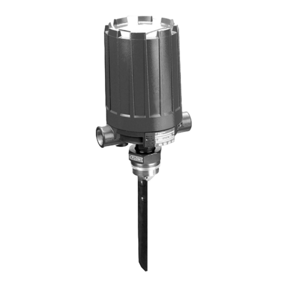
The F10 is a vane type flow switch designed to be installed
in 2" through 30" horizontal pipeline by means of a threaded
or flanged connection.
®
F10
Vane type
flow switches
OPERATING PRINCIPLE
The actuating vane is magnetically linked to a pivoted
electric (or pneumatic) switch, which is isolated from the
process by a non-magnetic barrier tube. As the actuating
vane moves with an increase in flow, it drives a magnetic
sleeve x into the field of a permanent magnet y located
outside the barrier tube z which trips the switch. As flow
decreases, the actuating vane returns to a vertical position,
allowing the magnet and switch assembly to return to the
"no Flow" position.
Switch mechanism
Adjusting screw
Magnetic sleeve
Magnet
Actuating vane
NO FLOW
POSITION
AGENCY APPROVALS
Agency
Approval
II 2G EEx d II C T6, explosion proof
ATEX
II 1G EEx ia II C T6, intrinsically safe
EEx d II C T6, explosion proof
CEnElEC
CCE Œ
R1 (1) 136/MI/433, explosion proof
Class I, Div. 1, Groups C & D
FM
Class II, Div. 1, Groups E, F & G, Type nEMA 7/9
FM/CSA
non-Hazardous area
Explosion proof area –
Groups B, C, D, E, F & G Type nEMA 4X/7/9
Explosion proof area
SAA
lRS
lloyds Register of Shipment (marine applications)
GOST/
Russian Authorisation Standards
GOSGORTECHnADZOR
Other approvals are available, consult factory for more details
ΠFor CCE approved units, use the ATEX explosion proof model
numbers.
Consult factory for proper model numbers.
POSITION WITH
ACTUATING FLOW PRESENT
Advertisement
Table of Contents

Related Manuals for Magnetrol F10


Summary of Contents for Magnetrol F10
- Page 1 INSTRUCTION MANUAL AND PARTS LIST DESCRIPTION OPERATING PRINCIPLE The F10 is a vane type flow switch designed to be installed The actuating vane is magnetically linked to a pivoted in 2" through 30" horizontal pipeline by means of a threaded electric (or pneumatic) switch, which is isolated from the or flanged connection.
- Page 2 This arrow should be pointing parallel with the flow arrow on the body bushing (as shown in Figure 4). The F10 flow switch should be located in a horizontal run If arrows are not parallel, remove the three vane sup- pipe with the arrow on the body bushing or mounting flange...
- Page 3 Inside bottom of run pipe SWITCH ACTUATION ADJUSTMENT The Model F10 flow switch is factory set to actuate at the Figure 6 minimum flow rate. Actuation flow rate can be increased while the unit is in service (under pressure) by removing x Electrical outlet may be rotated 360°...
- Page 4 2. Code for modified models or adders: put an "X" in front of the closest matching order code and specify the modifica- tions/adders separately eg. XF10-AD22-BK9 X = with material certification En 10204 / DIn 50049-3.1.B 1. Code for F10 flow switch BASIC MODEl nUMBER F 1 0 vane actuated flow switch – field adjustable setpoint Consult factory for steam applications.
- Page 5 (open air) 4,1 (60) +200 (+400) 2,39 (0.094) Series K 6,9 (100) +200 (+400) – (closed circuit) SPECIFICATIONS Model F10 flow switch with flanged connection Line size Dim. X max. Equivalent Rotation clearance max. wall schedule 2" 46 (1.81) 2 1/2"...
- Page 6 REPLACEMENT PARTS Item Description Qty. Carbon T304 SS T316 SS Forged T304 SS T316 SS steel mounting mounting mounting steel flange flange flange Switch housing cover See bulletin 42-780 for switch housings, items 2 & 3 only applicable on steel nEMA 4 housing, Switch housing base see bulletin 42-680.
- Page 7 REPLACEMENT PARTS (cont.) Serial number tage (ref.) Threaded mounting Flanged mounting...
- Page 8 SERVICE POLICY Owners of Magnetrol products may request the return of a control; or, any part of a control for complete rebuilding or replacement. They will be rebuilt or replaced promptly. Magnetrol International will repair or replace the control, at no cost to the purchaser, (or owner) other than transportation cost if: a.
Need help?
Do you have a question about the F10 and is the answer not in the manual?
Questions and answers