
Related Manuals for Magnetrol 3 Series


Summary of Contents for Magnetrol 3 Series
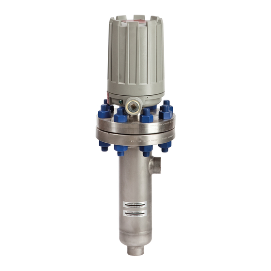
- Page 1 Series 3 Liquid Level Switches ASME B31.1 Construction Installation and Operating Manual...
- Page 2 MAGNETROL reserves the right to make changes to the narrative form. The following styles are used for notes, product described in this manual at any time without cautions, and warnings.
-
Page 3: Table Of Contents
Series 3 Liquid Level Switches ASME B31.1 Construction Table of Contents 1.0 Introduction 5.0 Reference Information 1.1 Principle of Operation ..........4 5.1 Agency Approvals............20 1.2 Operating Cycle ............4 5.2 Specifications ............21 5.2.1 Dimensional Data — Sealed Cage Models..21 2.0 Installation 5.2.2 Dimensional Specifications —... -
Page 4: Introduction
Introduction Enclosing tube The MAGNETROL Series 3 level switches are float oper- (non-magnetic) ated units suitable for use on clean liquid applications for level alarm, pump control and safety shutdown functions. Switch Units are designed, fabricated and certified to compliance... -
Page 5: Critical Alarm Function
Piping Pressure vessel Figure 3 shows a typical piping installation of a MAGNETROL Series 3 control to a pressure vessel. Level Switch actuating decals on control identify the actuation levels for the bot- level tom switch mechanism of a unit with three switches at... -
Page 6: Wiring
Controls should be mounted as close to the vessel as possi- ble. This will result in a more responsive and accurate level change in the control. Liquid in a long line may be cooler and more dense than liquid in the vessel causing lower level indication in the control than actual level in the vessel. - Page 7 5. The switch terminals are located next to the conduit outlet to facilitate wiring. Bring supply wires through conduit outlet. Route extra wire around enclosing tube under the baffle plate and connect them to the proper terminals. Refer to the wiring diagram in your switch bulletin for this information.
-
Page 8: Switch Differential Adjustment
Switch Differential Adjustment The standard differential of Series 3 float models with only one switch mechanism may be field-adjusted. Adjustment may be necessary if a wider differential needs to be set to overcome switch chatter caused by the process. The differential, or the amount of level travel between “switch-on”... -
Page 9: High Level Controls
NOTE: Level control, connections and pipe lines need not be removed from the tank. 6. Loosen enclosing tube nut with a ⁄ " wrench. Unscrew Slight enclosing tube counterclockwise (switch and housing base play (gap) Must be Figure 6 will rotate also) until it is free. Refer to on page 8. -
Page 10: Preventive Maintenance
To widen the differential by raising the trip point, follow steps 1 through 16 in Low Level Controls, Section 3.1 on pages 8 and 9. Caution: After increasing gap setting, be certain to check for proper operation of switch mechanism by raising and low- ering float assembly. -
Page 11: Switch And Wiring Inspection
Adjustment properly closed after each inspection of the switch screw mechanism(s). NOTE: In applications with presence of salt-laden air or corrosive Snap vapors, contact MAGNETROL for possible alternate switch switch mechanisms. Terminal screws 4.1.2 Switch and Wiring Inspection The switch mechanism and supply wiring need to be in proper position to assure correct switch operation. -
Page 12: Functional Test Of Unit
Lower level in the vessel sufficient to mechanism Baffle plate lower float and reset the switch. Confirm switch trips and resets at expected levels (contact MAGNETROL for spe- cific information on trip points; have the serial number of the unit readily available). Notches in... -
Page 13: What To Do - Every 12 Months (Minimum)
8. Verify that switch housing cover and conduit seal are Figure 15 properly closed after each inspection of the switch mechanism(s). NOTE: In applications with presence of salt-laden air or corrosive vapors, contact MAGNETROL for possible alternate switch mechanisms. 46-624 Series 3 Liquid Level Switches ASME B31.1 Construction... -
Page 14: Switch And Wiring Inspection
4.2.2 Switch and Wiring Inspection The switch mechanism and supply wiring need to be in proper position to assure correct switch operation. 1. Remove switch housing cover to inspect the supply wires. 2. Check that the supply wires are attached to the terminal Figure 14 block and run under the baffle plate. -
Page 15: Control Head Removal And Installation
4.2.3 Control Head Removal and Installation Inspection of the interior of the chamber is possible on flanged cage models. To do this, the control head must be removed to provide proper access to the chamber. This procedure will assure that the head assembly is removed and reinstalled properly. - Page 16 NOTE: Care must be taken not to place side force on the float which could bend the stem. Top jam Dim. A nuts 7. With the unit resting in its temporary fixture in an upright Bottom jam nuts position, it can now be inspected or repaired. Attraction 0.03"...
-
Page 17: Functional Test Of Unit
Lower level in the vessel sufficient to lower float and reset the switch. Confirm switch trips and resets at expected levels (contact MAGNETROL for spe- cific information on trip points; have the serial number of the unit readily available). -
Page 18: Check Switch Mechanism
4.3.1 Check Switch Mechanism 1. Pull switch or otherwise disconnect power to the control. 2. Remove switch housing cover. 3. Disconnect power wiring from switch assembly. 4. Swing magnet assembly in and out by hand to check care- fully for any sign of binding. Assembly should require minimal force to move it through its full swing. -
Page 19: What To Avoid
7. On installations without shutoff valves, relieve pressure from vessel and drain off liquid head above control mounting level. NOTE: Control chamber, connections, and pipe lines need not be removed from vessel or boiler. 8. Remove switch housing assembly by loosening enclosing tube hex nut, which is located immediately below housing base. -
Page 20: Reference Information
4. Never use lubricants on pivots of switch mechanisms. A sufficient amount of lubricant has been applied at the factory to ensure a lifetime of service. Further oiling is unnecessary and will only tend to attract dust and dirt which can interfere with mechanism operation. Reference Information Agency Approvals AgENCy... -
Page 21: Specifications
Specifications 5.2.1 Dimensional Data — Sealed Cage Models Inches (mm) NEMA 1: 8.50 (216) NEMA 4X/7/9: 10.12 (257) Group B: 10.12 (257) Plugged Plugged (Ref) (Ref) Figure 22 Threaded & Socket Weld Upper Side/Bottom Figure 23 Flanged Upper Side/Bottom Conduit Connections K Electrical Switches NEMA 4X/7/9: 1"... -
Page 22: Dimensional Specifications - Sealed Cage Models
5.2.2 Dimensional Specifications – Sealed Cage Models Inches (mm) CHAMBERS WITH 1-INCH CONNECTIONS — 150 LB. AND 300 LB. ANSI CLASS 1" NPT Threaded 1" Flanged 1" Flanged & Socket Weld Upper Side/Bottom Side/Side Model Code Std. 14" Std. 14" Std. - Page 23 5.2.2 Dimensional Specifications – Sealed Cage Models (cont.) Inches (mm) CHAMBERS WITH 1-INCH CONNECTIONS — 600 LB. & 900 LB. ANSI CLASS 1" NPT Threaded 1" Flanged 1" Flanged & Socket Weld Upper Side/Bottom Side/Side Model Code 14" 16" 14" 16"...
-
Page 24: Dimensional Data - Flanged Cage Models
5.2.3 Dimensional Data — Flanged Cage Models Inches (mm) NEMA 1: 8.50 (216) NEMA 4X/7/9: 10.12 (257) Group B: 10.12 (257) Plugged Plugged (Ref) (Ref) Figure 25 Threaded & Socket Weld Figure 26 Upper Side/Bottom Flanged Side/Side Conduit Connections K Electrical Switches NEMA 4X/7/9: 1"... -
Page 25: Dimensional Specifications - Flanged Cage Models
5.2.4 Dimensional Specifications – Flanged Cage Models 5.2.4.1 150# & 300# ANSI Pressure Ratings Inches (mm) CHAMBERS WITH 1-INCH CONNECTIONS 1" NPT Threaded 1" Flanged 1" Flanged & Socket Weld Upper Side/Bottom Side/Side Fig. Model Size Code (Lbs.) Std. 14" Std. -
Page 26: 600# & 900# Ansi Pressure Ratings
5.2.4.2 600# & 900# ANSI Pressure Ratings Inches (mm) CHAMBERS WITH 1-INCH CONNECTIONS 1" NPT Threaded 1" Flanged 1" Flanged & Socket Weld Upper Side/Bottom Side/Side Fig. Model Size Code (Lbs.) Std. 14" Std. 14" Std. 14" Std. 14" 9.12 3.63 18.39 14.00... -
Page 27: Actuating Levels, Steam Service Ratings And Specific Gravities
5.2.5 Actuating Levels*, Steam Service Ratings and Specific gravities For float operated units, minimum specific gravities and actuating levels vary depending upon the material of construction code used with the unit. NOTE: The minimum specific gravities and actuating levels shown are for single switch units with 1" process connections only. -
Page 28: Replacement Parts
Replacement Parts 5.3.1 Sealed Cage Float Models B35, C35, g35, v35 & Z35 Parts Identification Figure 28 Housing and Switch Mechanism Item Description Housing cover Housing base Switch mechanism Jam nuts (qty. 4) Washer Attraction sleeve Stop tube Enclosing tube ➀ E-tube gasket Chamber assembly Figure 29... -
Page 29: Flanged Cage Float Models B3F, G3F, K3F And Z3F Parts Identification
5.3.3 Flanged Cage Float Models B3F, g3F, K3F and Z3F Parts Identification Item Description Housing cover Housing base Switch mechanism Enclosing tube ➀ E-tube gasket Jam nuts (qty. 4) Washer (qty. 2) Attraction sleeve Stop tube Stop strap Screws (qty. 2) Float &... -
Page 30: Model Numbers
Model Numbers 5.4.1 Sealed Cage Models MODEL NUMBER CODE Pressure Rating ➀ Minimum Model Specific psig @ ° F bar @ ° C gravity ➁ Code 800 ➅ 427 ➅ 0.69 1000 68.9 60.3 55.5 54.0 0.57 34.5 30.2 27.8 27.4 0.54 51.7... - Page 31 ELECTRIC SWITCH MECHANISM AND ENCLOSURE Models B35, C35 & g35 Models v35 & Z35 Process ➄ TyPE 4X/7/9 Aluminum Enclosure Temperature Switch Contacts Range Description ATEX ATEX Points Class I, Div 1 Class I, Div 1 Class I, Div 1 Class I, Div 1 Ex II 2 G EEx Ex II 2 G EEx...
-
Page 32: Flanged Cage Models
5.4.2 Flanged Cage Models MODEL NUMBER CODE Pressure Rating ➁ Minimum S.g. ➀ Head Model gravity ➀ Flange psig @ ° F bar @ ° C Code ANSI Class 800 ∆ 427 ∆ 150# 0.78 19.6 10.7 300# 0.66 51.0 39.6 34.8 28.3... - Page 33 ELECTRIC SWITCH MECHANISM AND ENCLOSURE All models except B3F, g3F, K3F & Z3F Models B3F, g3F, K3F & Z3F Process ➅ with 600# or 900# ANSI ratings with 600# or 900# ANSI ratings Temperature Switch TyPE 4X/7/9 Aluminum Enclosure Contacts Range Description Points...
- Page 34 NOTES: 46-624 Series 3 Liquid Level Switches ASME B31.1 Construction...
- Page 35 NOTES: 46-624 Series 3 Liquid Level Switches ASME B31.1 Construction...
- Page 36 705 Enterprise Street • Aurora, Illinois 60504-8149 • 630-969-4000 • Fax 630-969-9489 info@magnetrol.com • www.magnetrol.com BULLETIN: 46-624.7 Copyright © 2015 Magnetrol International, Incorporated. All rights reserved. Printed in the USA. EFFECTIvE: August 2015 SUPERSEDES: January 2015...
Need help?
Do you have a question about the 3 Series and is the answer not in the manual?
Questions and answers