Advertisement
INSTRUCTION MANUAL AND REPLACEMENT PARTS
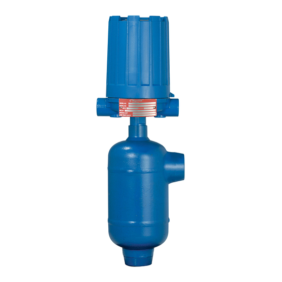
DESCRIPTION
Magnetrol's Series 75 level switches are float operated
units suitable for use on clean liquid applications for level
alarm, pump control and safety shutdown functions.
OPERATING PRINCIPLE
A permanent magnet
is attached to a pivoted switch
actuator
. As the float/ displacer
uid level, it raises the attraction sleeve
magnet, which then snaps against the non-magnetic
enclosing tube
, actuating the switch. The enclosing tube
provides a static pressure boundary between the switch
mechanism and the process. On a falling level, an inconel
spring retracts the magnet, deactivating the switch.
pivot
return spring
Rising level
UNPACKING
Unpack the instrument carefully. Inspect all units for dam-
age. Report any concealed damage to carrier within 24
hours. Check the contents of the packing slip and purchase
order. Check and record the serial number for future refer-
ence when ordering parts.
®
rises following the liq-
into the field of the
Falling level
SERIES 75
Liquid Level Switches
AGENCY APPROVALS
Agency
Approval
CENELEC
EEx d IIC T6, explosion proof
EEx ia IIC T6, intrinsically safe
BASEEFA
Ex d IIC T6
CSA
Non-Hazardous CSA Type 4X
Class I, Div. 2, Groups B, C & D
Class I, Div. 1, Groups C & D
Class II, Div. 1, Groups E, F & G
Class I, Div. 1, Groups B, C & D
Class II, Div. 1, Groups E, F & G
FM
Non-Hazardous NEMA 4X
Class I, Div. 1, Groups C & D
Class II, Div. 1, Groups E, F & G
Class I, Div. 1, Groups B, C & D,
Class II, Div. 1, Groups E, F & G
SAA
Ex d IIC T6 (IP65)
Not available with all switches; Consult factory for proper
model numbers.
Consult factory for proper model numbers.
Advertisement
Table of Contents

Related Manuals for Magnetrol 75 Series


Summary of Contents for Magnetrol 75 Series
- Page 1 ® Liquid Level Switches INSTRUCTION MANUAL AND REPLACEMENT PARTS DESCRIPTION Magnetrol’s Series 75 level switches are float operated units suitable for use on clean liquid applications for level alarm, pump control and safety shutdown functions. OPERATING PRINCIPLE A permanent magnet...
-
Page 2: Model Identification
MODEL IDENTIFICATION A complete series 75 liquid level switch, consists of 1 code: MODEL NUMBER – SPECIFIC GRAVITY & PRESSURE RATINGS — CARBON STEEL CHAMBERS Min. specific gravity Pressure rating Models with material construction code bar @ °C PSIG @ °F 40°... - Page 3 SELECT PNEUMATIC SWITCH MECHANISM & ENCLOSURE Pneumatic switch Max. supply pressure Max. liquid temperature Bleed orifice Ø Code (NEMA 3R encl.) description bar (PSIG) °C (°F) mm (inches) mat'l. code 1 mat'l. code 2 & 4 Series J bleed type 6.9 bar (100 PSIG) 200°C (400°F) 1.60 mm (0.063")
-
Page 4: Installation
Cable entry level alarm for maximum protection. PIPING Switch actuating Figure 3 shows a typical piping installation of a Magnetrol level Pressure reference vessel Series 75 control to a pressure vessel. Level decals on con-... -
Page 5: Switch Differential Adjustment
WIRING (cont.) OBSERVE ALL APPLICABLE ELECTRICAL CODES AND PROPER WIRING PROCEDURES CENELEC/BASEEFA NEMA 4x Figure 4a Set screw Locking screw Figure 4c NEMA 7/9 CAUTION: - DO NOT attempt to reposition NEMA 4 / NEMA 7/9 housings without loosening the set screws;... -
Page 6: High Level Controls
Figure 5 PREVENTIVE MAINTENANCE Periodic inspections are a necessary means to keep your Magnetrol level control in good working order. This control is, in reality, a safety device to protect the valuable equipment it serves. Therefore, a systematic program of "preven- tive maintenance"... -
Page 7: Troubleshooting
Certain adjust- factory to insure a lifetime of service. Further oiling is ments provided for in Magnetrol controls should not be attempted in the field. When in doubt, consult the facto- unnecessary and will only tend to attract dust and dirt which can interfere with mechanism operation. - Page 8 ACTUATING LEVELS Actuating levels shown are for single switch units at minimum specific gravity only. Levels will change for multistage units. Consult factory for these units. NPT & Socket weld Upper side/bottom Side/side Material code 1 (for minimum specific gravity) 1"...
- Page 9 SEALED CAGE MODEL DIMENSIONAL SPECIFICATIONS in mm (inches) – Only A75 Model – Rotation clearance Conduit connections NEMA 4X (IP 65) 109 (4.29) Electrical switches NEMA 4X (IP 65) 1” NPT, PG 16 or M20 x 1.5 entries NEMA 7/9 100 (3.94) (2 entries - one plugged) BASEEFA &...
- Page 10 SEALED CAGE MODEL DIMENSIONAL SPECIFICATIONS in mm (inches) Carbon steel and Stainless steel chambers with 1" and NW 25 (DIN) connections. 1" NPT & socket weld 1" or NW 25 1" or NW 25 Flanged upper side / bottom Flanged side / side Part n°...
- Page 11 REPLACEMENT PARTS Models with mat’l code 1 Models with mat’l code 2 Item Description A, B, C, G, J75 A, B, C, G, J75 Housing cover Housing Refer to bulletin 42-780 for switch housing cover and base assemblies kits Housing base Switch mechanism Refer to bulletin on switch mechanism furnished (listed on page 4) Jam nuts...
-
Page 12: Series 75 Tandem Float Units
SERIES 75 TANDEM FLOAT UNITS 1. Inspect for binding of solid (lower) float stem within DESCRIPTION hollow (upper) float stem due to corrosion or possible damage incurred in shipment. Series 75 units with tandem style floats are used on 2. Make certain that retaining “snap” rings, used to locate applications where widely spaced high and low switching lower attracting sleeve, are locked in place. - Page 14 SERVICE POLICY Owners of Magnetrol products may request the return of a control; or, any part of a control for complete rebuilding or replacement. They will be rebuilt or replaced promptly. Magnetrol International will repair or replace the control, at no cost to the purchaser, (or owner) other than transportation cost if: a.
Need help?
Do you have a question about the 75 Series and is the answer not in the manual?
Questions and answers
on a model 75 is there a mfr recommended torque spec for the enclosing tube . our drawings include bulletin 46-612 dated April 1976