
Related Manuals for Topcon DS Series


Summary of Contents for Topcon DS Series
- Page 1 SURVEYING INSTRUMENTS INSTRUCTION MANUAL Direct aiming Station DS series DS-201i DS-202i DS-203i DS-205i 21315 90080...
- Page 2 • Some of the diagrams shown in this manual may be simplified for easier understanding. • This manual is protected by copyright and all rights are reserved by TOPCON CORPORATION. • Except as permitted by Copyright law, this manual may not be copied, and no part of this manual may be reproduced in any form or by any means.
- Page 3 HOW TO READ THIS MANUAL Notes regarding manual style • Except where stated, “DS” means DS-201i/202i/203i/205i in this manual. • Turning using the Remote Controller and RC Handle is an optional function. In this manual, screens used in procedures are based on the instrument status the above optional function is effective. •...
-
Page 4: Table Of Contents
CONTENTS 1. PRECAUTIONS FOR SAFE OPERATION......1 2. PRECAUTIONS ..............4 3. LASER SAFETY INFORMATION .......... 8 4. PRODUCT OUTLINE............10 Parts of the Instrument ..............10 Mode Structure ................15 Bluetooth Wireless Technology/Wireless LAN ......16 5. BASIC OPERATION ............18 Basic Key Operation .............. - Page 5 12. MEASUREMENT WITH AUTO TRACKING ......70 12.1 Auto Tracking Settings ..............70 12.2 Measurement with Auto Tracking ..........72 13. MANEGING THE CAMERA TAB.......... 75 14. ANGLE MEASUREMENT............. 78 14.1 Measuring the Horizontal Angle between Two Points (Horizontal Angle 0°) ..............78 14.2 Setting the Horizontal Angle to a Required Value (Horizontal Angle Hold) ..............
- Page 6 22. CHANGING THE SETTINGS ..........129 22.1 Observation Conditions ............... 129 22.2 Instrument Configuration ............. 132 22.3 EDM Settings ................135 22.4 Allocating User-defined Tabs ............139 22.5 Customizing Screen Controls ............141 22.6 Allocating Key Functions ............. 143 22.7 Changing Starkey Mode Icons ............
- Page 7 32.1 Targets for Camera Check ............194...
-
Page 8: Precautions For Safe Operation
1. PRECAUTIONS FOR SAFE OPERATION For the safe use of the product and prevention of injury to operators and other persons as well as prevention of property damage, items which should be observed are indicated by an exclamation point within a triangle used with WARNING and CAUTION statements in this operator’s manual. The definitions of the indications are listed below. - Page 9 1. PRECAUTIONS FOR SAFE OPERATION Do not place the instrument in a case with a damaged catch, belt or handle. The case or instrument could be dropped and cause injury. Do not touch the instrument or look through the telescope while the motor is in operation. ...
- Page 10 1. PRECAUTIONS FOR SAFE OPERATION Caution Do not touch liquid leaking from batteries. Harmful chemicals could cause burns or blisters. Tripod Caution When mounting the instrument to the tripod, tighten the centering screw securely. Failure to tighten the screw properly could result in the instrument falling off the tripod, causing injury.
-
Page 11: Precautions
2. PRECAUTIONS Charging Battery • Be sure to charge the battery within the charging temperature range. Charging temperature range: 0 to 40°C Warranty policy for Battery • Battery is an expendable item. The decline in retained capacity depending on the repeated charging/ discharging cycle is out of warranty. - Page 12 2. PRECAUTIONS • Do not press the speaker / luminance sensor / microphone hole using something with a pointed tip. Doing so will damage an internal waterproof sheet, resulting in a degraded waterproof property. Speaker The Lithium Battery • The lithium battery is used to maintain the Calendar & Clock function. It can back up data for approximately 5 years of normal use and storage (Temperature = 20°, humidity = about 50%), but its lifetime may be shorter depending on circumstances.
- Page 13 2. PRECAUTIONS Maintenance • Wipe off moisture completely if the instrument gets wet during survey work. • Always clean the instrument before returning it to the case. The lens requires special care. First, dust it off with the lens brush to remove tiny particles. Then, after providing a little condensation by breathing on the lens, wipe it with the wiping cloth.
- Page 14 2. PRECAUTIONS Exceptions from responsibility • The user of this product is expected to follow all operating instructions and make periodic checks (hardware only) of the product’s performance. • The manufacturer, or its representatives, assumes no responsibility for results of faulty or intentional usage or misuse including any direct, indirect, consequential damage, or loss of profits.
-
Page 15: Laser Safety Information
3. LASER SAFETY INFORMATION The instrument is classified as the following class of Laser Product according to IEC Standard Publication 60825-1 Ed.2.0: 2007 and United States Government Code of Federal Regulation FDA CDRH 21CFR Part 1040.10 and 1040.11 (Complies with FDA performance standards for laser products except for deviations pursuant to Laser Notice No.50, dated June 24, 2007.) Device Laser class... - Page 16 3. LASER SAFETY INFORMATION • Do not look directly into the laser beam. Doing so could cause permanent eye damage. • Do not stare at the laser beam. Doing so could cause permanent eye damage. • Never look at the laser beam through a telescope, binoculars or other optical instruments. Doing so could cause permanent eye damage.
-
Page 17: Product Outline
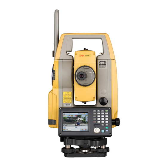
4. PRODUCT OUTLINE Parts of the Instrument Parts and functions of the instrument Wireless antenna Handle Beam detector for Remote Controller (option) Antenna hook External interface hatch (USB port/reset button) Instrument height mark Battery cover Display unit Circular level 10 Serial / External power source connector 11 Circular level adjusting screws 12 Base plate... - Page 18 4. PRODUCT OUTLINE Instrument height mark The height of the instrument is as follows: • 196mm (from tribrach mounting surface to this mark) "Instrument height" is input when setting instrument station data and is the height from the surveying point (where the instrument is mounted) to this mark. ...
- Page 19 4. PRODUCT OUTLINE Wireless antenna The wireless antenna allows communication via Bluetooth wireless technology and wireless LAN communication. • Handle the antenna with care or it may be damaged. • When removing the instrument from the carrying case, never pull the antenna. •...
- Page 20 4. PRODUCT OUTLINE To attache the handle, position the handle as shown, tighten the 2 handle rocking screws securely. Handle rocking screws Beam detector for Remote Controller and Contacts (Handle) (Option) • Never touch the beam detector. The ability of the system to perform Turning may be adversely affected.
- Page 21 4. PRODUCT OUTLINE Attaching the instrument to the tribrach 1. Check that the tribrach locking screw has been loosened. 2. Align (1) and (2) and lower the instrument onto the tribrach. 3. Turn the tribrach clamp (3) clockwise to tighten. 4.
-
Page 22: Mode Structure
4. PRODUCT OUTLINE Mode Structure The diagram below describes the different modes of the instrument and key operations for navigating between them. ●Basic mode Observation mode (switching by tab) Top menu Menu mode Version C“14. to 19” C “5.2 Display Config mode Functions ”Graphic“... -
Page 23: Bluetooth Wireless Technology/Wireless Lan
Contact your local dealer in advance. "30. REGULATIONS" • TOPCON CORPORATION is not liable for the content of any transmission nor any content related thereto. When communicating important data, run tests beforehand to ascertain that communication is operating normally. - Page 24 Moreover, as wireless devices lose signal strength when close to the ground, perform communication at as high a position as possible. • TOPCON CORPORATION cannot guarantee full compatibility with all Bluetooth/Wireless LAN products on the market.
-
Page 25: Basic Operation
5. BASIC OPERATION Learn basic key operations here before you read each measurement procedure. Basic Key Operation Display unit Illumination key { } { } { } Target type Program mode Input mode SHIFT SHIFT FUNC Function key Luminance sensor / Microphone Power ON/OFF ... - Page 26 5. BASIC OPERATION Switching to Program mode {PRG} Switches to program mode / basic mode • Do not switch between modes by {PRG} or not turn OFF the power just after pressing {PRG} (during displaying the message "Executing program mode"). Switching target type ...
- Page 27 5. BASIC OPERATION {ESC} Cancel the input data {TAB} Shift to the next item {B.S.} Delete a character on the left. Input a blank space (increments by 1 when setting the date and {S.P.} time) {}/{} Move the cursor left/right Move the cursor up/down ...
- Page 28 5. BASIC OPERATION 2. Press {7} three times. "c" is displayed. 3. Press {5} three times. "o" is displayed. 4. Press {}. Press {5}. "m" is displayed. 5. Continue to input letters. Press {ENT} to complete inputting.
-
Page 29: Display Functions
5. BASIC OPERATION Display Functions Screens can be selected/operated using the keys on the keyboard or the touch panel. The touch panel can be operated using either the stylus pen provided or your fingers. It is also possible to de-activate the touch panel temporarily. ... - Page 30 5. BASIC OPERATION Top menu Instrument name Serial Number Application software version Observation mode screen Camera tab Telescope reticle Measurement values Current magnification (ZA, HAR, SD) "Observation mode Page number screen SHV tab" Softkeys Current brightness (displayed only when brightness is changed) The "Camera"...
- Page 31 5. BASIC OPERATION Observation mode screen SHV tab (1) Distance (2) Vertical angle (3) Horizontal angle Softkeys Page number (1) Distance Horizontal distance and height difference are also displayed in "SHVdist" tab. Displayed items in "SHV" tab can be changed. ...
- Page 32 5. BASIC OPERATION Input screen/configuration screen Display all options Values can be input/ edited Observation mode screen Graphic tab Arrow indicates north as set backsight Target point Instrument station Scale (units: m) The "Graphic" tab display can be modified using the softkeys in the second page. [CNFG] : In <Graphic configuration>...
- Page 33 5. BASIC OPERATION Selecting menus To select a menu, tap the touch panel or press the relevant number key. Number Status bar Indicates the current status of the instrument. Tapping icons will switch between the relevant options for that item. Tapping and holding will display a list of all available options for that item and, in certain cases, a link to the configuration screen for that item.
-
Page 34: Inputting Characters Using The Input Panel
5. BASIC OPERATION Inputting Characters using the Input Panel α To display <Input Panel>, tap of status bar/Starkey mode or while pressing {SHIFT} press This keyboard can be used to input numeric and alphabetic characters as well as symbols. Tap the icon again to close. -
Page 35: Starkey Mode
5. BASIC OPERATION Starkey Mode Via Starkey mode, you can jump from each basic mode screen to the screen of checking/changing the ★ various settings directly. Press starkey { } to enter Starkey mode. Each icon can be tapped or pressed and hold in the same way with status bar. - Page 36 5. BASIC OPERATION When using external battery : Level 3 Full power : Level 2 Plenty of power remains : Level 1 Half or less power remains : Level 0 Little power remains. Prepare a replacement battery. "6.1 Battery Charging" (2) Target type icon Selection of target type and configuration of prism constant correction value.
- Page 37 5. BASIC OPERATION • Auto Tracking and Auto Pointing cannot be performed when "Reflectorless" has been selected as the target type. will be displayed. Auto Tracking cannot be performed when "Sheet" has been selected as the target type. will be displayed •...
- Page 38 5. BASIC OPERATION i) Connection via Bluetooth wireless technology When DS is set as the "Master" device the antenna icon is blue. When the DS is set as the "Slave" device the antenna icon is green. : Connecting : Canceling connection : (Antenna is moving) Inquiring about other Bluetooth devices : (Antenna is stationary) Communication settings in progress/Preparing for communication (Instrument just powered ON or just switched to "Slave")
- Page 39 5. BASIC OPERATION (11) Touch panel icon De-activate the touch panel temporarily or go to Inst. Config. :Touch panel temporarily de-activated. • This icon cannot be operated during distance measurement, or during data transmission. (12) Disk usage icon Tap and hold disk icon in the status bar to check the detail of the disk usage. : Less than 20% : 20 to 50% : More than 50%...
-
Page 40: Using The Program Selection Screen
5. BASIC OPERATION Using the Program Selection Screen The program selection screen displays a list of all programs installed on the instrument. Each screen page contains a maximum of 5 program icons. When multiple screen pages exist, navigating between pages is possible using the arrows that appear at the left/right of the screen. An icon without an allocated program cannot be selected... -
Page 41: Using The Battery
6. USING THE BATTERY Battery Charging The battery was not charged at the factory. Charge the battery fully before using the instrument. • The charger will become rather hot during use. This is normal. • Do not use to charge batteries other than those specified. •... -
Page 42: Installing/Removing The Battery
6. USING THE BATTERY 5. Remove the battery and unplug the charger. • Slots 1 and 2: The charger starts charging the battery mounted first. If you place two batteries in the charger, the battery in slot 1 is charged first, and then the ... - Page 43 6. USING THE BATTERY PROCEDURE Mounting the battery 1. Slide down the catches on the battery cover to open. Battery cover 2. Insert the battery in the direction of the arrow on the side of the battery. • Do not insert the battery inclined. Doing so may damage the instrument or battery terminals.
-
Page 44: Setting Up The Instrument
7. SETTING UP THE INSTRUMENT • Mount the battery in the instrument before performing this operation because the instrument will tilt slightly if the battery is mounted after levelling. Centering PROCEDURE Centering with the optical plummet eyepiece 1. Make sure the legs are spaced at equal intervals and the head is approximately level. - Page 45 7. SETTING UP THE INSTRUMENT 4. Adjust the levelling foot screws to center the survey point in the optical plummet reticle. 5. Continue to the levelling procedure. "7.2 Levelling" PROCEDURE Centering with the laser plummet (Option) 1. Set up the tripod and affix the instrument on the tripod head.
-
Page 46: Levelling
7. SETTING UP THE INSTRUMENT 4. Use [-]/[+] in the second page to adjust the brightness of the laser. 5. Adjust the position of the instrument on the tripod until the laser beam is aligned with the center of the survey point. - Page 47 7. SETTING UP THE INSTRUMENT 3. Power ON the instrument. "8. POWER ON/OFF" The electric circular level is displayed on the <Tilt>. “” indicates the bubble in circular level. The range of the inside circle is ±1.5' and the range of the outside circle is ±6'.
-
Page 48: Power On/Off
8. POWER ON/OFF • When the power cannot be switched ON or the power is soon turned OFF even though the battery is mounted, there may be almost no battery power remaining. Replace it with a fully charged battery. ... -
Page 49: Configuring The Touch Panel
8. POWER ON/OFF PROCEDURE Power OFF 1. Press and hold (about 1sec) { • When there is almost no battery power remaining, the battery icon in the status bar will start to blink.In this event, stop measurement, switch off the power and charge the battery or replace with a fully charged battery. -
Page 50: Resolving Software Issues
8. POWER ON/OFF Resolving Software Issues If you are experiencing problems with the instrument and suspect a fault in the program, you should try a warm boot. If the problem is not resolved with a warm boot the next step is to perform a cold boot. A warm boot will not erase surveying data in the instrument but will cancel the resume function. -
Page 51: Powering On/Off From An External Instrument
8. POWER ON/OFF Powering ON/OFF from an External Instrument The instrument can be powered ON/OFF from an external device such as a computer or data collector. • The password must be input after powering ON the instrument from an external device when a password has been set. -
Page 52: Connecting To External Devices
9. CONNECTING TO EXTERNAL DEVICES The instrument supports Bluetooth wireless technology, RS232C and Wireless LAN for communication with data collectors etc. Inputting/outputting data is also possible by inserting a USB memory or by connecting to a USB device. Read this manual in conjunction with the operator’s manual for the relevant external device. - Page 53 9. CONNECTING TO EXTERNAL DEVICES Set "Comms mode" in the "Comms setup" tab to "Bluetooth". • Changing communication settings during Bluetooth communication will cancel the connection. • The status bar icon cannot be tapped in <Communication Setup>. • Do not change the setting’ (2) to (7) from the factory setting, when performing Bluetooth communication with a recommended data collector.
- Page 54 9. CONNECTING TO EXTERNAL DEVICES 2. Check that "Mode" in the "Bluetooth" tab is set to "Slave". • Only "Slave" can be selected when the instrument is shipped. 3. Set "Authentication" to "Yes" or "No". If "Authentication" is set to "Yes" for the DS the passkey will also need to be input on the companion device.
- Page 55 9. CONNECTING TO EXTERNAL DEVICES 3. Press [LIST] to display a list of all registered devices (no devices are registered when the instrument is shipped). 4. Press [SEARCH] in the "Serial" tab to search about communication-ready Bluetooth devices in the immediate vicinity of the instrument. When the search is completed, their device name and address are displayed in a list.
- Page 56 9. CONNECTING TO EXTERNAL DEVICES • Press [Delete] to delete the selected device name. Deleted device names cannot be retrieved. • Select a device and press [Edit] in the second page to update the device name and/or device address. 5. Press [OK] to complete registration. PROCEDURE Set Bluetooth communication mode to "Master"...
-
Page 57: Communication Between The Ds And Companion Device
9. CONNECTING TO EXTERNAL DEVICES PROCEDURE Displaying Bluetooth information for the DS 1. Select "Comms" in Config mode. 2. Press [Info] in the "Bluetooth" tab to display information for the DS. Register the Bluetooth address (BD ADDR) displayed here in the paired device set as "Master". - Page 58 9. CONNECTING TO EXTERNAL DEVICES 3. Terminate the connection by the data collector. PROCEDURE Bluetooth communication as "Master" 1. Complete the necessary DS settings for Bluetooth communication. " 9.1 Wireless Communication using Bluetooth Technology " PROCEDURE Set Bluetooth communication mode to "Master"" and "...
-
Page 59: Connection Via Rs232C Cable
9. CONNECTING TO EXTERNAL DEVICES Connection via RS232C Cable RS232C communication is possible, connecting instrument and a data collector with the cable. PROCEDURE Basic cable settings 1. Power OFF the instrument and connect the instrument and a data collector with a interface cable. -
Page 60: Connecting Via Usb Cable
USB port 1 USB port 2 (mini-B) • TOPCON CORPORATION cannot guarantee that all USB devices are compatible with the DS USB ports. • Use a computer WindowsXP/Vista/7 is based and USB connection is capable. • Remove the USB cable from USB port 2 carefully to avoid damaging the cable. - Page 61 9. CONNECTING TO EXTERNAL DEVICES PROCEDURE Connecting the instrument to a computer to transfer data from instrument in USB mode When connecting Windows XP, "exFat file system driver" needs to be installed to the computer. 1. Open the external interface hatch by sliding its button.
- Page 62 9. CONNECTING TO EXTERNAL DEVICES 5. Press { } and hold (about 1sec) to turn off the instrument to exit USB mode connection. PROCEDURE Connecting the instrument to a computer to transfer data from instrument in Mobile mode A synchronous software needs to be installed to the computer depending on the Windows version. Computer to connect Synchronous software Windows XP...
-
Page 63: Inserting Usb Memory
9. CONNECTING TO EXTERNAL DEVICES 4. If synchronous software displays a partner setting screen on the computer and asks whether to set a partner device, press [NO]. • A partner setting screen may not be displayed depending on the synchronous software settings. -
Page 64: Starting Up External Link And Settings
10.STARTING UP EXTERNAL LINK AND SETTINGS Use Wireless LAN to transfer image data captured by the built-in camera to the data collector. Start up External Link in the program selection screen to setup for Wireless LAN. Setup for Bluetooth communication/RS232C can also be performed here. ... - Page 65 10. STARTING UP EXTERNAL LINK AND SETTINGS 3. Press [WIRELESS LAN] in <SETTING>. 4. Set "WIRELESS LAN" to "Enable" and set "AdHoc CHANNEL" to be corresponded to the data collector used. Items set and options (*: Factory setting) (1) WIRELESS LAN:Enable*/Disable (2) AdHoc CHANNEL:1 to 11 (11*) 5.
- Page 66 10. STARTING UP EXTERNAL LINK AND SETTINGS 8. Tap Wireless LAN icon. 9. Select "DS-(serial number of your instrument)" and press [Connect] to start communication. • Connection status of Wireless communication is displayed as follows. : Connecting The more bars are displayed as the signal level is stronger.
- Page 67 10. STARTING UP EXTERNAL LINK AND SETTINGS PROCEDURE Necessary settings for Wireless LAN communication (when communicating DS and the external device through Wireless LAN access point) 1. Set communication conditions for the data collector used. " PROCEDURE Necessary settings for Wireless LAN communication (when communicating DS and the external device directly) step 1 to 4.
- Page 68 10. STARTING UP EXTERNAL LINK AND SETTINGS 5. Select a Wireless LAN access point and press [Connect]. <Wireless Properties> is displayed. 6. Set necessary security settings for the Wireless LAN connection. 7. Press [OK] to finish settings and return to the screen in step 5.
- Page 69 10. STARTING UP EXTERNAL LINK AND SETTINGS 3. Press [SET] to finish settings. • Connection status via Bluetooth wireless technology is displayed as follows. : Connecting : Canceling connection PROCEDURE Necessary settings for RS232C 1. Start up External Link. ...
-
Page 70: Target Sighting
11.TARGET SIGHTING A target can be automatically sighted using the Auto Pointing function or manually sighted by the operator using the sighting collimatorand telescope. When Auto Pointing is performed, the image sensor on the Offset instrument detects the light beam reflected from the target (prism of X direction or reflective sheet target), the offset between the target and telescope reticle is calculated by image processing, then the angle... -
Page 71: Auto Pointing Settings
11. TARGET SIGHTING 11.1 Auto Pointing Settings PROCEDURE 1. Select "Motor" in <Configuration>. Set Auto Pointing functions in the Configuration tab. Set "Search Setting" to "Search". Items set and options (*: Factory setting) (1) AUTO AIM Fine/Rapid* (2) Search Setting : None/Search/Track* (3) Srch method ... - Page 72 11. TARGET SIGHTING Srch method Selects search before distance measurement option. When set to "G.S." the instrument will search for the target in the area specified in the Search area tab. When set to "R.C.", the instrument will wait for a Turning command to be issued from the Remote Controller before starting Auto Pointing.
-
Page 73: Auto-Pointing Function For Target Sighting
11. TARGET SIGHTING Search pattern The search pattern is the rotating method of telescope and instrument to find the target prism in search mode. In Pattern "1" instrument starts searching the prism at the point where the prism is lost and gradually expands the searching area in vertical direction, keeping the horizontal angular width. - Page 74 11. TARGET SIGHTING 2. Press [SRCH] in any Observation mode screen. The telescope and top half of the instrument rotate and target auto-search begins. When the target is found, the instrument sights the prism and stops. Allocating the [SRCH] softkey: "22.6 Allocating Key Functions"...
-
Page 75: Manually Sighting The Target
11. TARGET SIGHTING 11.3 Manually Sighting the Target • When sighting the target, strong light shining directly into the objective lens may cause the instrument to malfunction. Protect the objective lens from direct light by attaching the lens hood. Observe to the same point of the reticle when the telescope face is changed. - Page 76 11. TARGET SIGHTING Sighting manually When sighting manually, set "Search Setting" to "None" in <Motor Configuration> Configuration tab, then use the Sighting collimator to bring the target into the field of view. When the target is in the field-of-view, use the Jogs to make fine adjustments and accurately sight the center of the prism.
-
Page 77: Measurement With Auto Tracking
12.MEASUREMENT WITH AUTO TRACKING With the Auto Tracking function, the instrument searches for and sights the target. The instrument will then following that target as it is moved from measurement point to measurement point. The Remote Control System is recommended for high performance Auto Tracking measurement. ... - Page 78 12. MEASUREMENT WITH AUTO TRACKING Configuration tab: "11.1 Auto Pointing Settings" 2. Set the area in which to perform target sighting in the Search area tab. Search area tab: "11.1 Auto Pointing Settings" Step 2 3. When necessary, set the Jog turning speed for vertical and horizontal rotation of the telescope.
-
Page 79: Measurement With Auto Tracking
12. MEASUREMENT WITH AUTO TRACKING 12.2 Measurement with Auto Tracking PROCEDURE 1. Use the sighting collimator to aim the objective lens in the general direction of the target. (The vertical and horizontal Jogs can be used for precise adjustments of the instrument and telescope.) ... - Page 80 12. MEASUREMENT WITH AUTO TRACKING Auto Tracking Obstacle Auto Tracking continues in predicted Target found direction Target not found Target found "Target lost" Target not found Target found "Prism wait" Target not found Target found Re-search Target not found Sighting terminates (Auto Tracking idle) ...
- Page 81 12. MEASUREMENT WITH AUTO TRACKING Rotates in a counterclockwise direction (from the Rotates in a point of view of the Remote Controller) then counterclockwise performs Auto Pointing/Auto Tracking direction (from the point [<-RC] of view of the Remote Controller) then performs Auto Pointing Rotates in a clockwise direction (from the point of Rotates in a clockwise...
-
Page 82: Maneging The Camera Tab
13.MANEGING THE CAMERA TAB The view from the built-in camera is displayed on the screen in the Camera tab of the Observation mode. This section explains about functions in the Camera tab. Displayed items and softkeys Telescope reticle Measurement values Current magnification (ZA, HAR, SD) Page number... - Page 83 13. MANEGING THE CAMERA TAB Camera setting screen When observing the sun, attach the solar filter and the set the sunlignt mode in this screen. "27. OPPTIONAL ACCESSORIES" Select higher value as the sunlight becomes brighter. Items set and options (*: Factory setting) Sunlight Mode : Off*/1/2/3 Sighting and measurement...
- Page 84 13. MANEGING THE CAMERA TAB Automatic elimination of parallax Parallax here is the difference of the positions between the telescope reticle and the top corner of the triangle displayed on the screen. There exists a parallax because the built-in camera and the telescope are not on the same axis.
-
Page 85: Angle Measurement
14.ANGLE MEASUREMENT This section explains the procedures for basic angle measurement in Observation mode. • It is possible to allocate softkeys in measurement menus to suit various applications and the ways that different operators handle the instrument. "22.6 Allocating Key Functions" 14.1 Measuring the Horizontal Angle between Two Points (Horizontal Angle 0°) -
Page 86: Setting The Horizontal Angle To A Required Value (Horizontal Angle Hold)
14. ANGLE MEASUREMENT 14.2 Setting the Horizontal Angle to a Required Value (Horizontal Angle Hold) You can reset the horizontal angle to a required value and use this value to find the horizontal angle of a new target. PROCEDURE 1. Sight the first target. 2. -
Page 87: Turning The Instrument From The Reference Angle To A Specified Angle
14. ANGLE MEASUREMENT 14.3 Turning the Instrument from the Reference Angle to a Specified Angle The instrument automatically turns from the reference direction to the specified angle (target). • instrument also turns to the target coordinates when reference angle is omitted. ... -
Page 88: Angle Measurement And Outputting The Data
14. ANGLE MEASUREMENT Fixed velocity rotation The instrument horizontal angle and telescope can be rotated using the controls in the Fixed velocity rotation tab. Speed settings are from 1 to 16. Allocate [Fix Vel] in Observation mode to use this function. Tap the touch panel in the desired rotation direction. -
Page 89: Distance Measurement
15.DISTANCE MEASUREMENT Perform the following settings as preparation for distance measurement in Observation mode. • Distance measurement mode • Target type • Prism constant correction value • (Target) Aperture • ppm • Search area • Auto Pointing/Auto Tracking "11.1 Auto Pointing Settings", "12.1 Auto Tracking Settings", "22.3 EDM Settings" •... -
Page 90: Returned Signal Checking
15. DISTANCE MEASUREMENT 15.1 Returned Signal Checking Check to make sure that sufficient reflected light is returned by the target sighted by the telescope. Checking the returned signal is particularly useful when performing long distance measurements. Caution • The laser beam is emitted during returned signal checking. ... -
Page 91: Distance And Angle Measurement
15. DISTANCE MEASUREMENT 3. Press [OFF] to finish signal checking. Press {ESC} or tap the cross in the top-right corner to return to the previous screen. • When is displayed persistently, but “ ” is not, contact your local dealer. ... -
Page 92: Distance Measurement And Outputting The Data
15. DISTANCE MEASUREMENT The measured distance data (SD), vertical angle (ZA), and horizontal angle (HAR) are displayed. 3. Press [STOP] to quit distance measurement. • If the single measurement mode is selected, measurement automatically stops after a single measurement. •... -
Page 93: Rem Measurement
15. DISTANCE MEASUREMENT 15.4 REM Measurement An REM measurement is a function used to measure the height to a point where a target cannot be directly installed such as power lines, overhead cables and bridges, etc. The height of the target is calculated using the following formula. Ht = h h2 = S sin x cot... - Page 94 15. DISTANCE MEASUREMENT 3. Sight the target and press [MEAS] to start measurement. Press [STOP] to stop the measurement. The measured distance data, vertical angle and horizontal angle are displayed. 4. Sight the object, then press [REM] to start REM measurement is started.
-
Page 95: Coordinate Measurement
16.COORDINATE MEASUREMENT By performing coordinate measurements it is possible to find the 3-dimensional coordinates of the target based on station point coordinates, instrument height, target height, and azimuth angles of the backsight station which are entered in advance. • It is possible to allocate softkeys in measurement menus to suit various applications and the ways that different operators handle the instrument. -
Page 96: Azimuth Angle Setting
16. COORDINATE MEASUREMENT 3. Select "Occupy setup" and enter instrument station coordinates,instrument height (HI) and target height (HR). 4. Press [OK] to set the input values. <Set H angle> is displayed again. 16.2 Azimuth Angle Setting Based on the instrument station coordinates and backsight station coordinates which have already been set, the azimuth angle of the backsight station is calculated. - Page 97 16. COORDINATE MEASUREMENT PROCEDURE Entering coordinates 1. Select "Backsight setup" in <Coordinate>. <Set H angle> is displayed. • <Set H angle> can also be displayed from the screen in step 4 of "16.1 Entering Instrument Station Data". 2. Select the "Key in coord" tab and enter the backsight station coordinates.
- Page 98 16. COORDINATE MEASUREMENT PROCEDURE Entering angle 1. Select "Backsight setup" in <Coordinate>. <Set H angle> is displayed. • <Set H angle> can also be displayed from the screen in step 4 of "16.1 Entering Instrument Station Data". 2. Select the "Key in angle" tab and enter the desired angle in "H.ang".
-
Page 99: 3-D Coordinate Measurement
16. COORDINATE MEASUREMENT Horizontal angle settings Azimuth (set both horizontal and azimuth angles to the same value)/H.ang (input both horizontal and azimuth angles)/None (input azimuth angle only)/0 SET (horizontal angle set to 0°) 16.3 3-D Coordinate Measurement The coordinate values of the target can be found by measuring the target based on the settings of the instrument station and backsight station. - Page 100 16. COORDINATE MEASUREMENT 2. Select "Coord." in <Coordinate>. Press [MEAS] to start measurement. Press [STOP] to stop the measurement. The coordinates of the target point are displayed. Select the "Graphic" tab to display coordinates on a graph. 3. Sight the next target and press [MEAS] to begin measurement.
-
Page 101: Resection Measurement
17.RESECTION MEASUREMENT Resection is used to determine the coordinates of an instrument station by performing multiple measurements of points whose coordinate values are known. Registered coordinate data can be recalled and set as known point data. Residual of each point can be checked, if necessary. Entry Output Coordinates of... -
Page 102: Coordinate Resection Measurement
17. RESECTION MEASUREMENT 17.1 Coordinate Resection Measurement N, E, Z of an instrument station is determined by the measurement. PROCEDURE 1. Select "Resection" in <Menu>. 2. Select "NEZ" to display <Resection/Known point>. 3. Input the known point. After setting the coordinates and target height for the first known point press [NEXT] to move to the second point. - Page 103 17. RESECTION MEASUREMENT 4. Sight the first known point and press [MEAS] to begin measurement. The measurement results are displayed on the screen. • When [ANGLE] has been selected, the distance cannot be displayed. 5. Press [YES] to use the measurement results of the first known point.
- Page 104 17. RESECTION MEASUREMENT [CALC] [YES] 7. Press to automatically start calculations after observations of all known points are completed. • Instrument station coordinates, station elevation, and standard deviation, which describes the measurement accuracy, are displayed. Standard deviation for the northing, easting and elevation coordinates of each point are displayed in the "Detail"...
- Page 105 17. RESECTION MEASUREMENT • Press [RE OBS] to measure the point designated in step 8. If no points are designated in step 8, all the points or only the final point can be observed again. • Press [ADD] in the second page when there is a known point that has not been observed or when a new known point is added.
-
Page 106: Height Resection Measurement
17. RESECTION MEASUREMENT 17.2 Height Resection Measurement Only Z (height) of an instrument station is determined by the measurement. • Known points must be measured by distance measurement only. • Between 1 and 10 known points can be measured. PROCEDURE 1. - Page 107 17. RESECTION MEASUREMENT 4. Sight the first known point and press [MEAS] to begin measurement. The measurement results are displayed on the screen. 5. If measuring two or more known points, repeat procedures 4 in the same way from the second point.
- Page 108 17. RESECTION MEASUREMENT 7. If there are problems with the results of a point, align the cursor with that point and press [OMIT]. “OMIT” is displayed to the right of the point. Repeat for all results that include problems. 8. Press [RE CALC] to perform calculation again without the point designated in step 7 The result is displayed.
- Page 109 17. RESECTION MEASUREMENT Resection calculation process The NE coordinates are found using angle and distance observation equations, and the instrument station coordinates are found using the method of least squares. The Z coordinate is found by treating the average value as the instrument station coordinates. Calculated instrument station coordinates set as hypothetical coordinates...
- Page 110 17. RESECTION MEASUREMENT Precaution when performing resection In some cases it is impossible to calculate the coordinates of an unknown point (instrument station) if the unknown point and three or more known points are arranged on the edge of a single circle.
-
Page 111: Setting-Out Measurement
18.SETTING-OUT MEASUREMENT Setting-out measurement is used to set out the required point. The difference between the previously input data to the instrument (the setting-out data) and the measured value can be displayed by measuring the horizontal angle, distance or coordinates of the sighted point. - Page 112 18. SETTING-OUT MEASUREMENT PROCEDURE 1. Select "Setting out" in <Menu> to display <Setting out>. 2. Select "Occupy setup" to display <Occupy setup>. Enter data for the instrument station and press [OK] to move to Backsight setup. "16.1 Entering Instrument Station Data" 3.
- Page 113 18. SETTING-OUT MEASUREMENT 4. Select "SO data setting" In <Setting out> to display <SO data setting>. In the distance mode that conforms to your measurement requirements, enter the included angle between the reference point and the setting-out point in "SO.H.ang", and the distance (slope distance, horizontal distance or height difference) from the instrument station to the position to be set out in "SO.Sdist".
- Page 114 18. SETTING-OUT MEASUREMENT • Press [CNFG] to set setting out accuracy. When the position of the target is within this range both arrows will be displayed to indicate that the target position is correct. 6. Position the target on the line of sight and press Arrows indicate direction to move [MEAS] to begin distance measurement.
-
Page 115: Coordinates Setting-Out Measurement
18. SETTING-OUT MEASUREMENT 7. Move the target until the distance to the setting- out point reads 0m. When the target is moved within the allowed range, all distance and position arrows are displayed. 8. Press {ESC} to return to <Setting out>. Set the next setting out point to continue setting out measurement. - Page 116 18. SETTING-OUT MEASUREMENT PROCEDURE 1. Select "Setting out" in <Menu> to display <Setting out>. 2. Select "Occupy setup" to display <Occupy setup>. If necessary, enter data for Backsight setup. "18.1 Distance Setting-out Measurement" steps 2 to 3 3. Select "Key in coord" in <Setting out>. Record all the setting-out points (includes setting-out points you will measure from now).
- Page 117 18. SETTING-OUT MEASUREMENT 5. Position the target on the line of sight and press Press [H.TURN] to automatically rotate the instrument until the angle of the setting out point reads 0°. [MEAS] to begin distance measurement. The distance and direction to move the target until the setting out point is located is displayed on the instrument.
- Page 118 18. SETTING-OUT MEASUREMENT Move the target to find the correct distance (0 is displayed) to the setting out point. Movement indicators: "18.1 Distance Setting- out Measurement" step 6 6. Press [OK] to return to <Key in coord>. Set the next setting out point to continue setting out measurement.
-
Page 119: Rem Setting-Out Measurement
18. SETTING-OUT MEASUREMENT 18.3 REM Setting-out Measurement To find a point where a target cannot be directly installed, perform REM setting-out measurement. "15.4 REM Measurement" PROCEDURE 1. Install a target directly below or directly above the point to be found. Then use a measuring tape etc. to measure the target height (height from the survey point to the target). - Page 120 18. SETTING-OUT MEASUREMENT 5. Sight the target and press [MEAS]. Measurement begins and the measurement results are displayed. 6. Press [REM] to start REM measurement. Arrows indicate direction to move The distance (height difference) and direction to move the target until the sighting point and setting out point are located is displayed on the instrument.
-
Page 121: Offset Measurement
19.OFFSET MEASUREMENT Offset measurements are performed in order to find a point where a target cannot be installed directly or to find the distance and angle to a point which cannot be sighted. • It is possible to find the distance and angle to a point you wish to measure (target point) by installing the target at a location (offset point) a little distance from the target point and measuring the distance and angle from the survey point to the offset point. - Page 122 19. OFFSET MEASUREMENT 2. Select "Offset" in <Menu> to display <Offset>. 3. Select "Occupy setup" to display <Occupy setup>. Enter data for the instrument station and press [OK] to move to Backsight setup. "16.1 Entering Instrument Station Data" 4. Set the azimuth angle for the backsight station. Press [OK] to return to <Offset>.
-
Page 123: Offset Angle Measurement
19. OFFSET MEASUREMENT 6. Sight the offset point and press [MEAS] in the Results for target point screen of step 5 to start measurement. Press [STOP] to stop the measurement. The measurement results are displayed. • Press [HVD/nez] to switch results for the target point between distance/angle values and coordinate/elevation values. - Page 124 19. OFFSET MEASUREMENT 2. Select "Offset" in <Menu> to display <Offset>. Select "OffsetANG.". 3. Sight the offset point and press [MEAS] to start measurement. Press [STOP] to stop the measurement. 4. Sight the target point and press [H.ANG]. Results for target point •...
-
Page 125: Offset Two-Distance Measurement
19. OFFSET MEASUREMENT 19.3 Offset Two-distance Measurement By measuring the distances between the target point and the two offset points. Install two offset points (1st target and 2nd target) on a straight line from the target point, observe the 1st target and 2nd target, then enter the distance between the 2nd target and the target point to find the target point. - Page 126 19. OFFSET MEASUREMENT PROCEDURE 1. Install two offset points (1st target, 2nd target) on a straight line from the target point and use the offset points as the target. 2. Select "Offset" in <Menu> to display <Offset>. Select "5.Offset2D". 3. Press [CNFG] and input the distance from the 2nd target to the target point in "Offset dist.".
- Page 127 19. OFFSET MEASUREMENT 5. Sight the 2nd target and press [MEAS] to start measurement. Press [STOP] to stop the measurement. The measurement results are displayed. 6. Press [YES] to display results for the target point. Press [HVD/nez] to switch results for the target point between distance/angle values and coordinate/elevation values.
-
Page 128: Missing Line Measurement
20.MISSING LINE MEASUREMENT Missing line measurement is used to measure the slope distance, horizontal distance, and horizontal angle to a target from the target which is the reference (starting point) without moving the instrument. • It is possible to change the last measured point to the next starting position. •... - Page 129 20. MISSING LINE MEASUREMENT 2. Sight the starting position, and press [MEAS] to start measurement. Press [STOP] to stop measurement. • When measurement data already exists the screen of step 3 is displayed and measurement starts. 3. Sight the next target and press [MLM] to Results for measurement between starting begin observation.
-
Page 130: Changing The Starting Point
20. MISSING LINE MEASUREMENT 20.2 Changing the Starting Point It is possible to change the last measured point to the next starting position. PROCEDURE 1. Observe the starting position and target following steps 1 to 3 in "20.1 Measuring the Distance between 2 or more Points". - Page 131 20. MISSING LINE MEASUREMENT Press [YES] in the confirmation message window. • Press [NO] to cancel measurement. 3. The last target measured is changed to the new starting position. 4. Perform missing line measurement following steps 3 to 4 in "20.1 Measuring the Distance between 2 or more Points".
-
Page 132: Surface Area Calculation
21.SURFACE AREA CALCULATION You can calculate the area of land (slope area and horizontal area) enclosed by three or more known points on a line by inputting the coordinates of the points Input Output Coordinates: P1 (N1, E1, Z1) Surface area: S (horizontal area and slope area) P5 (N5, E5, Z5) - Page 133 21. SURFACE AREA CALCULATION PROCEDURE Surface area calculation by measuring points 1. Select "Area calc." in <Menu> 2. Press [OBS] to display <Area calculation/ measurement>. Sight the first point on the line enclosing the area, and press [MEAS]. Measurement begins and the measured values are displayed.
- Page 134 21. SURFACE AREA CALCULATION 3. The measurement results are displayed. Press [YES] to confirm.The value of point 1 is set in "Pt_01". 4. Repeat steps 2 to 3 until all points have been measured. Points on an enclosed area are observed in a clockwise or counterclockwise direction.
- Page 135 21. SURFACE AREA CALCULATION 5. Press [CALC] to display the calculated area. 6. Press [OK] to return to <Area/key in coord.>. Press {ESC} or tap the cross in the top-right corner to quit area calculation.
-
Page 136: Changing The Settings
22.CHANGING THE SETTINGS This section explains the contents of parameter settings in Basic mode and how to change these settings. Each item can be changed to meet your measurement requirements. <Configuration> can be accessed by pressing the "CONFIG" icon in <Top>. The following chapters provide details of items in Configuration mode. - Page 137 22. CHANGING THE SETTINGS Items set and options (*: Factory setting) Distance mode : Sdist (slope distance)*/Hdist (horizontal distance)/ V.dist (height difference) Hdist : Ground*/Grid Tilt crn (tilt correction) : Yes (H,V)*/No, Yes (V) Tilt error : No action*/Go to <Tilt> (electric circular level is displayed) Coll.crn.
- Page 138 22. CHANGING THE SETTINGS Collimation correction The instrument has a collimation correction function that automatically corrects horizontal angle errors caused by horizontal axis and leveling axis errors. Normally set this item to "Yes". V mode (vertical angle display method) Horiz 90°...
-
Page 139: Instrument Configuration
22. CHANGING THE SETTINGS 22.2 Instrument Configuration Items set and options (*: Factory setting) Power off : No/5min./10min./15min./30min.* Power off (Remote) : No*/5min./10min./15min./30min. Backlight (Reticle On) : 0 to 8 (1*) (Brightness level on pressing {}) Backlight (Normal) : 0 to 8/Auto (Auto*) Backlight Off ... - Page 140 22. CHANGING THE SETTINGS Adjusting backlight brightness/turning the reticle illumination and key backlight ON/OFF Pressing {} switches the brightness level of the backlight in conjunction with the ON/OFF status of the reticle illumination/key backlight. When the instrument is powered ON the brightness level is set to "Backlight (Normal)". "Backlight (Normal)"...
- Page 141 22. CHANGING THE SETTINGS Key backlight The key backlight can be set to "ON" or "OFF". When "key backlight" is set to "ON", the key backlight is lit /OFF in conjunction with pressing {}. EDM ALC Set the light receiving status of the EDM. While carrying out continuous measurement, set this item according to the measurement conditions.
-
Page 142: Edm Settings
22. CHANGING THE SETTINGS 22.3 EDM Settings "EDM" tab Items set, options, and input range (*: Factory setting) Dist. mode (Distance measurement mode): Fine ’R’*/Fine AVG n= 1(Setting: 1 to 9 times)/Fine ’S’/Rapid ’R’/Rapid ’S’/Tracking Reflector : Prism*/360° Prism/Sheet/N-Prism Prism constant value : -99 to 99 mm ("Prism"... - Page 143 22. CHANGING THE SETTINGS "ppm" tab • [0ppm]: Atmospheric correction factor returns to 0 and temperature and air pressure are set to the factory settings. • Atmospheric correction factor is calculated and set using the entered values of the temperature and air pressure.
- Page 144 22. CHANGING THE SETTINGS • e (water vapor pressure) can be calculated using the following formula. × --------- - × 7.5 t --------------------------- - 237.3 × 6.11 10 • The instrument measures the distance with a beam of light, but the velocity of this light varies according to the index of refraction of light in the atmosphere.
- Page 145 22. CHANGING THE SETTINGS PROCEDURE Recording and editing target information The [LIST] softkey is displayed when either "Reflector" or "Prism const." is selected in the "EDM" tab of <EDM configurations>. 1. Press [LIST] to display a list of all recorded targets.
-
Page 146: Allocating User-Defined Tabs
22. CHANGING THE SETTINGS 22.4 Allocating User-defined Tabs It is possible to allocate tabs in Observation mode and Menu mode to suit the measurement conditions. It is possible to operate the instrument efficiently because unique tab allocations can be preset to suit various applications and the ways that different operators handle the instrument. •... - Page 147 22. CHANGING THE SETTINGS PROCEDURE Allocating tabs 1. Select "Customize" to display <Customize/Select screen>. Select the measurement mode in which you want to allocate a tab. Select "Tab page". 2. Use the softkeys ([ADD], [DEL] etc.) in <Customize tab page> to allocate the desired tab page layout.
-
Page 148: Customizing Screen Controls
22. CHANGING THE SETTINGS Select a tab type from the "Type" drop-down list. 3. Repeat step 2 to perform further tab allocations. 4. Press [OK] to finish allocating tabs. The allocated tabs are stored in memory and <Customize> is displayed. The newly allocated tabs appear in the relevant measurement screen. - Page 149 22. CHANGING THE SETTINGS Select "Control". 2. Press [ADD] to add a control drop-down list. • Press [DEL] to delete the selected control. • Controls, once deleted, cannot be retrieved. 3. Select a screen control from the list. 4. Press [CNFG] to set the size, thickness, color and spacing of the font.
-
Page 150: Allocating Key Functions
22. CHANGING THE SETTINGS 6. Press [OK] to finish customizing screen controls. The modifications are stored in memory and <Customize> is displayed. The modifications are reflected in the relevant screens. 22.6 Allocating Key Functions It is possible to allocate the softkeys in Observation mode to suit the measurement conditions. It is possible to operate the instrument efficiently because unique softkey allocations can be preset to suit various applications and the ways that different operators handle the instrument. - Page 151 22. CHANGING THE SETTINGS [R/L] : Select horizontal angle right/left. The capitalized letter in the softkey indicates the currently selected mode. [ZA / %] : Switch between zenith angle/slope in %. The capitalized letter in the softkey indicates the currently selected mode. [HOLD] : Hold horizontal angle/release horizontal angle [CALL]...
- Page 152 22. CHANGING THE SETTINGS [RESEC] : Resection measurement [AREA] : Surface area measurement [CNFG] : Set setting out accuracy (can only be allocated to 2 and 3 above) [H.TURN] : Rotate the instrument to the entered horizontal angle. Rotate horizontally to the angle for the setting out point when performing setting out (can only be allocated to 2 and 3 above).
-
Page 153: Changing Starkey Mode Icons
22. CHANGING THE SETTINGS 2. Select the desired tab. All softkeys currently allocated to each page of that tab are displayed. 3. Select the softkey whose allocation you want to change. Tapping a softkey, or pressing {SPACE} when the cursor is aligned with a softkey, will display <Softkey list>. - Page 154 22. CHANGING THE SETTINGS • When icon allocations are recorded and registered, the setting reflects to Status bar. Icons that can be allocated to the status bar Remaining battery power Target display Motor Laser-pointer Tilt angle compensation Communication status Input mode SIP (Input panel) ppm (atmospheric correction factor)
-
Page 155: Units
22. CHANGING THE SETTINGS 3. Select the new icon from <Starkey list>. The icon is allocated in the selected icon position. 4. Repeat steps 2 to 3 to perform further icon allocations. 5. Press {ENT} to finish allocating icons. The allocated icons are stored in memory and <Customize/Select screen>... -
Page 156: Changing Password
22. CHANGING THE SETTINGS Inch (Fraction of an inch) “Fraction of an inch” is the unit used in the United States and expressed like the following example. • Even if “inch” is selected in this setting, all the data including the result of area calculation are output in “feet”... -
Page 157: Date And Time
22. CHANGING THE SETTINGS Items set Old password : Input current password New password : Input the new password New password again : Input the new password again 22.10 Date and Time Items set Date : Manually input date or select from the drop-down calendar by tapping . -
Page 158: Restoring Default Settings
22. CHANGING THE SETTINGS 22.11 Restoring Default Settings Perform a cold boot to return all items to factory settings. A cold boot will not erase surveying data in instrument. However, if the data in the memory is important, BE SURE TO TRANSFER IT TO A PERSONAL COMPUTER BEFORE PERFORMING A COLD BOOT. -
Page 159: Warning And Error Messages
23.WARNING AND ERROR MESSAGES The following is a list of the error messages displayed by the instrument and the meaning of each message. If the same error message is repeated or if any message not shown below appears, the instrument has malfunctioned. Contact your local dealer. Backup battery dead. - Page 160 23. WARNING AND ERROR MESSAGES Error: Read Build Info. Error: Read JOG Setting Error: Read OS Parameter Error: Read RCOR Error: Read sysflg Error: Self check Error: Write sysflg Press [OK] to cancel the message. If this error message appears frequently, contact your local dealer.
- Page 161 23. WARNING AND ERROR MESSAGES Please input an address consisting of 12 hexadecimal characters (0 to 9, A to F) The Bluetooth address is not input correctly for Bluetooth communication. Input the Bluetooth address with 12 characters of 0 to 9 or A to F. Remote Control communication err !! Communication between the Remote controller for Remote Control System and the instrument failed.
-
Page 162: Checks And Adjustments
24.CHECKS AND ADJUSTMENTS DS is a precision instrument that requires fine adjustments. It must be inspected and adjusted before use so that it always performs accurate measurements. • Always perform checking and adjustment in the proper sequence beginning from "24.1 Circular Level"... -
Page 163: Tilt Sensor
24. CHECKS AND ADJUSTMENTS 3. First confirm the off-center direction. Use the adjusting pin to loosen the circular level adjustment screw on the side opposite to the direction the bubble is displaced to move the bubble to the center. 4. Adjust the adjusting screws until the tightening tension of the three screws is the same to align the bubble in the middle of the circle. - Page 164 24. CHECKS AND ADJUSTMENTS 3. Select "Tilt offset". 4. Level the instrument until the X/Y tilt angles are ±1’. Wait a few seconds for the display to stabilize, then read the current tilt angle in the X (sighting) direction and Y (horizontal axis) direction.
- Page 165 24. CHECKS AND ADJUSTMENTS 9. Confirm that the values are in the adjustment Results for target point range. If both correction constants are within the range the current value ±1’, select [YES] to renew the correction angle. <Instrument constants> is restored. Continue to step 11. If the values exceed the adjustment range, select [NO] to cancel the adjustment and return to the screen in step 4.
-
Page 166: Collimation
24. CHECKS AND ADJUSTMENTS 24.3 Collimation With this option you can measure collimation error in your instrument so that the instrument can correct subsequent single face observations. To measure the error, make angular observations using both faces. PROCEDURE 1. Carefully level the instrument. 1. -
Page 167: Reticle
24. CHECKS AND ADJUSTMENTS 4. Sight the reference point in Face 2 and press [OK]. 5. Press [YES] to set the constant. • Press [NO] to discard the data and return to the screen in step 3. 24.4 Reticle With this option you can check the perpendicularity of the reticle and the horizontal/vertical positions of reticle lines. - Page 168 24. CHECKS AND ADJUSTMENTS 3. Use the fine motion screws to align the target to point B on a vertical line. If the target moves parallel to the vertical line, adjustment is unnecessary. If its movement deviates from the vertical line, have our service representative adjust it.
-
Page 169: Image Sensor Reticle
24. CHECKS AND ADJUSTMENTS 24.5 Image Sensor Reticle The internal image sensor is used for automatic sighting. The offset value is set to correct the position of the image sensor in relation to the telescope reticle, but if for whatever reason the telescope reticle and image sensor become misaligned, automatic sighting of the center of the prism cannot be performed correctly. - Page 170 24. CHECKS AND ADJUSTMENTS 5. Use manual sighting to accurately sight the target. "11.3 Manually Sighting the Target" 6. Press [OK]. 7. Offset value (H, V) (New) is obtained from the set Set offset value offset value (H, V) (Current) and the measurement results.
-
Page 171: Camera
24. CHECKS AND ADJUSTMENTS 24.6 Camera With this option you can check if the built-in camera is aligned correctly. If for whatever reason the camera becomes misaligned, images cannot be displayed correctly on the camera tab. Checking is performed using the target at the back of this manual. ... - Page 172 24. CHECKS AND ADJUSTMENTS 6. Check the image on the screen. When the telescope reticle displayed on the Camera is aligned correctly screen is inside the green target circle, camera is aligned correctly. The adjustment is unnecessary. Camera is misaligned When the telescope reticle is outside the target circle, camera is misaligned.
-
Page 173: Rc Handle (Option)
24. CHECKS AND ADJUSTMENTS 24.7 RC Handle (Option) To perform Turning using the Remote Controller system correctly, the search area for Turning is already set when the instrument was shipped. But if for whatever reason the target cannot be found or it takes longer time to find the target, offset the search area to its proper position as described below. - Page 174 24. CHECKS AND ADJUSTMENTS 2. Select "RC Handle offset". 3. Press [ ← ]/ [ → ] to offset the search area to its proper position. • Press [INIT] to return offset value settings to its factory setting center. 4. Press [OK] to renew the offset value and return to <Instrument constants>.
-
Page 175: Optical Plummet
24. CHECKS AND ADJUSTMENTS 24.8 Optical Plummet • Be careful that the tightening tension is identical for all the adjusting screws. • Also, do not over-tighten the adjusting screws as this may damage the circular level. PROCEDURE Checking 1. Carefully level the instrument and center a survey point precisely in the reticle of the optical plummet. -
Page 176: Additive Distance Constant
24. CHECKS AND ADJUSTMENTS If the survey point is on the solid line (dotted line): Loosen the right (left) adjusting screw slightly and, tighten the left (right) adjusting screw by the same amount to move the survey point to a point in the center of the optical plummet. -
Page 177: Laser Plummet (Option)
24. CHECKS AND ADJUSTMENTS 3. Place the instrument at point C directly between points A and B and set up the reflective prism at point A. 4. Precisely measure the horizontal distances CA and CB 10 times each and calculate the average value for each distance. - Page 178 24. CHECKS AND ADJUSTMENTS PROCEDURE Adjustment 1. Turn the laser plummet adjustment cap anticlockwise and remove. 2. Emit the laser plummet beam. 3. Note the current position (x) of the laser beam. 4. Turn the upper part of the instrument horizontally through 180°...
- Page 179 24. CHECKS AND ADJUSTMENTS Slightly loosen the upper (lower) screw and tighten the lower (upper) screw. Make sure that the tightening tension for both screws is identical. Continue to adjust until the laser beam is on the horizontal line of the target. 7.
-
Page 180: Power Supply System
25.POWER SUPPLY SYSTEM Operate your instrument with the following combinations of power equipment. • When using an external battery, mount the BDC70 in place to maintain the balance of the instrument. • Never use any combination other than those indicated below. If you do, the instrument could be damaged. -
Page 181: Prism System
26.PRISM SYSTEM Arrangement according to your needs is possible. Target pole-2 (not used with 9 prisms) Prism-2 Tilting prism Tilting prism Triple prism Single prism Tilting triple 9 prism holder-2 holder-3 holder-2 holder-2 prism holder-1 holder-2 with target Plug-3 plate-2 Tribrach Tribrach adaptor-2... -
Page 182: Opptional Accessories
27.OPPTIONAL ACCESSORIES The following are optional accessories which are sold separately from the instrument. Power supply and target optional accessories: "25. POWER SUPPLY SYSTEM", "26. PRISM SYSTEM". Plumb bob The plumb bob can be used to set up and center the instrument on days when there is little wind. - Page 183 27. OPPTIONAL ACCESSORIES Diagonal eyepiece (DE27) The diagonal eyepiece is convenient for DE27 observations near the nadir and in narrow spaces. Magnification: 30X After removing the handle from the instrument loosen the attachment screw to remove the telescope eyepiece. Then screw the diagonal lens into place.
- Page 184 27. OPPTIONAL ACCESSORIES Remote Controller (RC-5) This is the remote controller for Remote Control System which points the instrument (DS) in the direction of the prism with speed and precision. Remote Control System Manual • This system can be used only when the RC Handle is attached to the instrument (DS).
-
Page 185: Specifications
28.SPECIFICATIONS Except where stated, the following specifications apply to all DSs. Telescope Length 168mm Aperture 45mm (1.8 inch) (EDM: 50mm (2.0 inch)) Magnification Image Erect Resolving power 2.5" Field of view 1°30' (26m/1,000m) Minimum focus 1.3m (4.3ft) Focussing screw 1 speed Reticle illumination 5 brightness levels Angle measurement... - Page 186 28. SPECIFICATIONS Distance measurement Measuring method Coaxial phase-contrast measuring system Signal source Red laser diode 690nm Class 3R (IEC60825-1 Ed. 2.0: 2007/FDA CDRH 21CFR Part1040.10 and 1040.11 (Complies with FDA performance standards for laser products except for deviations pursuant to Laser Notice No.50, dated July 26, 2001.)) (When target (reflector) is set to prism or reflective sheet, the output is equivalent to Class 1)
- Page 187 28. SPECIFICATIONS (8 + 10ppm X D) mm (over 200 to 350m) (15 + 10ppm X D) mm (over 350 to 1,000m) (ISO 17123-4 : 2001) Measurement mode Fine measurement (single/repeat/average)/Rapid measurement (single/repeat)/Tracking (selectable) Measuring time (fastest time under good atmospheric conditions , no compensation, EDM ALC at appropriate setting, slope distance) Fine measurement:...
- Page 188 28. SPECIFICATIONS Prism-5: 1.3 to 500 m (1,640 ft) Prism-2: 1.3 to 1,000 m (3,280 ft) *10,*12 Auto Tracking speed 15°/sec Auto Pointing Measuring method Pulse laser transmitter and image sensor with co-axial optics Signal source (emitted beam) infrared laser diode (980 nm) Class 1 (IEC60825-1 Ed.
- Page 189 28. SPECIFICATIONS Motor Type DC motor drive Motion range 360°(Vertical and horizontal) Rotation speed 70°/sec (at 20°C) (Rotating time: about 8 sec. (when rotating 180°, tilt compensation off, at 20°C)) Fine motion Operated by jogs (minimal unit of motion is about 1") Camera Pixel 5M pixel, QSXGA...
- Page 190 28. SPECIFICATIONS Bluetooth profile SPP, DUN Power class Class 1 *21,*22 Usable range to 150 m (While in communication with designated controllers) Authentication Yes/No (selectable) *20 : Bluetooth function may not be built in depending on telecommunications regulations of the country or the area where the instrument is purchased.
- Page 191 28. SPECIFICATIONS Battery (BDC70) Nominal voltage: 7.2V Capacity: 5,240 mAh Dimensions: 40 (W) x 70 (D) x 40 (H) mm Weight: about 197g Charger (CDC68A) Input voltage: AC100 to 240V Charging time per battery (at 25°C): BDC70: about 5.5 hours (Charging can take longer than the times stated above when temperatures are either especially high or low.) Charging temperature range: 0 to 40°C Storage temperature range:-20 to 65°C...
- Page 192 28. SPECIFICATIONS Weight 6.2kg (13.7lb) (with BDC70, tribrach and standard Handle) 6.3kg (13.9lb) (with BDC70, tribrach and RC Handle)
-
Page 193: Explanations
29.EXPLANATIONS 29.1 High Accuracy with the 360° Prism Sighting can be more accurately performed by facing the 360° Prism toward the instrument. The 360° Prism should be set up so that a pair of diametrically-opposed hexagonal points on its rubber flanges are aligned with the sighting direction of the instrument (see the diagram below). -
Page 194: Manually Indexing The Vertical Circle By Face Left, Face Right Measurement
29. EXPLANATIONS 29.2 Manually Indexing the Vertical Circle by Face Left, Face Right Measurement The 0 index of the vertical circle of your instrument is almost 100% accurate, but when it is necessary to perform particularly high precision angle measurements, you can eliminate any inaccuracy of the 0 index as follows. -
Page 195: Regulations
Declaration of Conformity Model Number: DS series Trade Name: TOPCON CORPORATION Manufacture Name: TOPCON CORPORATION Address: 75-1, Hasunuma-cho, Itabashi-ku, Tokyo, 174-8580 JAPAN Country:JAPAN U.S.A. Representative Responsible party: TOPCON POSITIONING SYSTEMS,INC. Address 7400 National Drive Livermore, CA94551, U.S.A Telephone number: 925-245-8300... - Page 196 30. REGULATIONS Region/ Directives/ Labels/Declarations Country Regulations California, Proposition U.S.A California, Perchlorate U.S.A Material (CR Lithium Battery) California Recycling and NY, Batteries U.S.A.
- Page 197 Hereby, TOPCON CORP., declares that the above-mentioned equipment is in compliance with the essential requirements and other relevant provisions of Directive 1999/5/EC. Please inquire below if you wish to receive a copy of Topcon's Declaration of Conformity. Topcon Europe Positioning B.V.
- Page 198 30. REGULATIONS Region/ Directives/ Labels/Declarations Country Regulations WEEE Directive EU Battery Directive...
-
Page 199: Index
31.INDEX ACK mode ..........................46 Adjusting backlight brightness/turning the reticle illumination and key backlight ON/OFF ..133 Atmospheric correction factor ....................136 AUTO AIM ..........................64 Automacic elimination of parallax ....................77 Automatic tilt angle compensation mechanism ................ 130 Bluetooth connection mode ....................... 45 Bluetooth device address ...................... - Page 200 31. INDEX Slope area ..........................125 Srch method ..........................65 Terminate ...........................46 Trigger key ..........................11 TURN ............................65 Turning operation ........................74 V mode (vertical angle display method) ...................131 Vertical Jog ..........................11...
-
Page 201: Appendix
32.APPENDIX 32.1 Targets for Camera Check Print and use targets here to check if the built-in camera is aligned correctly. "24.6 Camera" • Print this page in color and in the same magnification. Target for positioning 5 m from the instrument (radius: 2.63 mm) Target for positioning 10 m from the instrument (radius: 5.25 mm) Target for positioning 20 m from the instrument (radius: 10.50 mm) - Page 202 Please see the attached address list or the following website for contact addresses. GLOBAL GATEWAY http://global.topcon.com/ © 2014TOPCON CORPORATION ALL RIGHTS RESERVED...
Need help?
Do you have a question about the DS Series and is the answer not in the manual?
Questions and answers