Table of Contents
Advertisement
Advertisement
Table of Contents

Related Manuals for Topcon RL-SV2S


Summary of Contents for Topcon RL-SV2S
- Page 1 INSTRUCTION MANUAL ROTATING LASER RL-SV2S 31365 90030...
- Page 3 “ STANDARD SYSTEM COMPONENTS” (p. iii) • The specifications and general appearance of the instrument are subject to change without prior notice and without obligation by Topcon Corporation and may differ from those appearing in this manual. • Some of the diagrams shown in this manual may be simplified for easier understanding.
-
Page 4: How To Read This Manual
HOW TO READ THIS MANUAL Symbols The following conventions are used in this manual. Indicates precautions and important items which should be read before operations. Indicates the chapter title to refer to for additional information. Indicates supplementary explanation. -
Page 5: Standard System Components
STANDARD SYSTEM COMPONENTS Rechargeable battery type Dry battery type 1) RL-SV2S Instrument ........1pc. 1) RL-SV2S Instrument........1pc. 2) Remote controller RC-60 2) Remote controller RC-60 (with AA Manganese battery x 2pcs.) .....1pc. (with AA Manganese battery x 2pcs.) .... 1pc. -
Page 6: Table Of Contents
RC-60 Nomenclature ....................14 RC-60 Display......................14 4.3 Level Sensor LS-80L ....................15 LS-80L Nomenclature ....................15 LS-80L Display......................16 LS-80L Detective Range................... 17 5. PREPARATION AND FUNCTIONS ..................18 5.1 Power Source ....................... 18 RL-SV2S (Dry battery type) ..................18... -
Page 7: Contents
CONTENTS RL-SV2S (Rechargeable battery type)..............20 RC-60........................23 LS-80L........................23 5.2 How to set remote controller communication channel ..........24 RL-SV2S ........................24 RC-60........................24 6. BASIC OPERATION......................25 6.1 Setting Up Instrument ....................25 Horizontal Rotation....................25 Example Operational....................27 Vertical Rotation...................... - Page 8 CONTENTS How to change the rotary head speed ..............42 Switching Auto leveling / Manual Mode ..............43 Setting channel ......................44 Sleep mode ON/OFF ....................44 Height Alert ON/OFF....................46 8. CHECK AND ADJUSTING....................47 8.1 Check and Adjust Horizontal Rotation ................47 Horizontal rotation grade error ..................
-
Page 9: Precautions For Safe Operation
1. PRECAUTIONS FOR SAFE OPERATION For the safe use of the product and prevention of injury to operators and other persons as well as prevention of property damage, items which should be observed are indicated by an exclamation point within a triangle used with WARNING and CAUTION statements in this instruction manual. - Page 10 1. PRECAUTIONS FOR SAFE OPERATION General Warning Do not perform disassembly or rebuilding. Fire, electric shock or burns could result. Do not use the unit in areas exposed to high amounts of dust or ash, in areas where there is inadequate ventilation, or near combustible materials. An explosion could occur.
- Page 11 1. PRECAUTIONS FOR SAFE OPERATION Power Supply Warning Do not short circuit. Heat or ignition could result. Do not use voltage other than the specified power supply voltage. Fire or electrical shock could result. Do not use damaged power cords, plugs or loose outlets. Fire or electric shock could result.
- Page 12 1. PRECAUTIONS FOR SAFE OPERATION Do not heat or throw batteries into fire. An explosion could occur, resulting in injury. Do not use the battery or charger for any other equipment or purpose. Fire or burns caused by ignition could result. To prevent shorting of the battery in storage, apply insulating tape or equivalent to the terminals.
- Page 13 1. PRECAUTIONS FOR SAFE OPERATION Tripod Caution When mounting the instrument to the tripod, tighten the centering screw securely. Failure to tighten the screw properly could result in the instrument falling off the tripod, causing injury. Tighten securely the leg fixing screws of the tripod on which the instrument is mounted.
-
Page 14: Precautions
2. PRECAUTIONS Before starting work or operation, be sure to check that the instrument is functioning correctly with normal performance. Vibration and Impact Protection When transporting the instrument, provide protection to minimize risk of severe vibration or impact. Severe vibration or impacts may affect beam accuracy. Protection against abrupt change in temperature Do not leave the instrument under strong sunlight for a long time. - Page 15 2. PRECAUTIONS • The manufacturer, or its representatives, assumes no responsibility for consequential damage, and loss of profits by any disaster, (an earthquake, storms, floods etc.). A fire, accident, or an act of a third party and/or a usage any other usual conditions. •...
-
Page 16: Laser Safety Information
3. LASER SAFETY INFORMATION The RL-SV2S is classified as a class 3R Laser Product according to IEC Standard Publication 60825-1 Ed.2.0: 2007 and United States Government Code of Federal Regulation FDA CDRH 21CFR Part1040.10 and 1040.11 (Complies with FDA performance standards for laser products except for deviations pursuant to Laser Notice No.50, dated June 24, 2007.) - Page 17 3. Laser Safety Information CLASS IIIa LASER PRODUCT Visible laser VISIBLE LASER BEAM Laser output: 2.4mW Beam aperture Explanatory Label Each lavel is differed by the market. Warning Use of controls or adjustments or performance of procedures other than those specified herein may result in hazardous radiation exposure.
- Page 18 3. Laser Safety Information Do not stare at the laser beam. Doing so could cause permanent eye damage. Never intentionally point the laser beam at another person. The laser beam is injurious to the eyes and skin. Caution Perform checks at start of work and periodic checks and adjustments with the laser beam emitted under normal conditions.
-
Page 19: Nomenclature
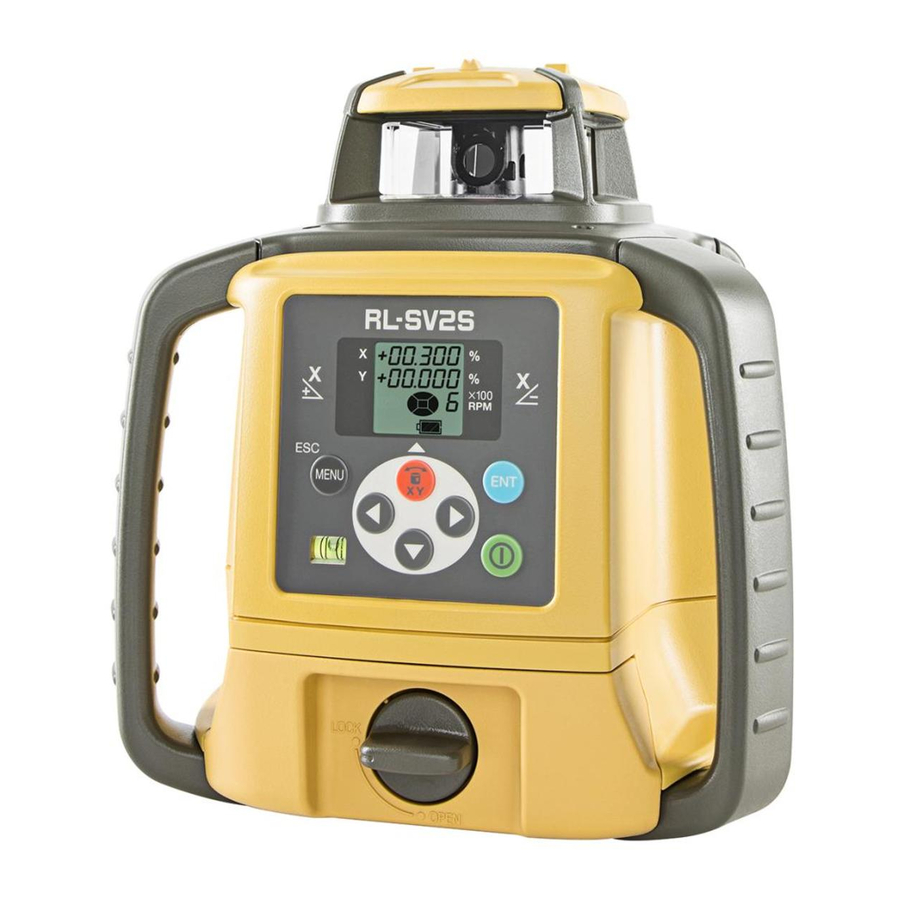
4. NOMENCLATURE 4.1 RL-SV2S RL-SV2S Nomenclature Rotary head Sight Beam apeature Control panel X/Y axis selection key/ Alignment key/ Up key Menu key/ Handle Enter key Escape key Power switch Level vial For Vertical Rotation Arrow keys Battery holder Control panel... - Page 20 X/Y axis selection key/ each axis. Alignment key Vertical rotation: changes to the Alignment Mode. The arrows indicate code selection, digit shift, and number Arrow keys input during grade setting, and designates direction during masking setting. Power switch On/Off of the RL-SV2S.
-
Page 21: Rl-Sv2S Display
4. Nomenclature RL-SV2S Display Sample display X axis grade (Flashes one digit at a time Mask Mode display during leveling) Y axis grade Rotation speed 6:600/rpm (Flashes one digit at a time 3:300/rpm during leveling) 5:500/rpm (Flashes when the battery is low) -
Page 22: Remote Controller Rc-60
Enter key Arrow keys X/Y axis selection key/Alignment key/ Up key Strap hole RC-60 Display Display is the same as the RL-SV2S. “RL-SV2S Display” (p. 13) Battery power display will show the remaining battery level on the RC-60 remote controller. -
Page 23: Level Sensor Ls-80L
Beam receiving window Buzzer sound switch Turn the beam receiving window side Volume of the sensor buzzer can be towards RL-SV2S to detect the laser alternately switched to beam. LOW/LOUD/OFF by pressing the switch. Buzzer speaker... -
Page 24: Ls-80L Display
Battery remaining display Battery is sufficient. The warning displays *1 and *2 are the functions that the LS-80L detects alarm signal from the RL-SV2S. The power is low, but laser The LS-80L can be canceled the alarm detection from the is still usable. -
Page 25: Ls-80L Detective Range
4. Nomenclature LS-80L Detective Range... -
Page 26: Preparation And Functions
5. PREPARATION AND FUNCTIONS 5.1 Power Source Connect the battery according to the battery type purchased. RL-SV2S (Dry battery type) • How to install dry cell batteries Remove the DB-74 battery holder by turning battery holder knob to "OPEN" side. - Page 27 5. Preparation and Functions • How to remove dry cell batteries Remove the DB-74 battery holder by turning battery holder knob to "OPEN" side. Remove the dry cell batteries from the DB-74 battery holder. *1 Replace all 4 batteries with new ones at the same time. Do not mix used and new batteries, and do not mix different types of batteries together.
-
Page 28: Rl-Sv2S (Rechargeable Battery Type)
5. Preparation and Functions RL-SV2S (Rechargeable battery type) • How to install the battery pack Insert the battery pack BT-74Q into the DB-74C battery holder in the direction shown in the diagram on the right. Install the battery holder. Tighten the battery cover knob to "LOCK"... - Page 29 5. Preparation and Functions • For Charging AD-15 Plug Plug the AC/DC converter (AD-15) into the DB-74C battery holder or plug the AD-15 into the battery pack BT-74Q. Insert the AD-15 power cord in an outlet. Complete charging by unplugging the plug from the DB-74C battery holder or battery pack BT-74Q after approximately 13 hours.
- Page 30 5. Preparation and Functions • Recharging should take place in a room with an ambient temperature range of 10°C to 40°C (50°F to 104°F). • Do not perform charging with others except the AC/DC converter AD-15. • For longer battery life, conform to the suggested charging time to the extent possible. •...
-
Page 31: Rc-60
5. Preparation and Functions RC-60 • How to install dry cell batteries Open the battery cover. Remove the old batteries and replace with new 2xAA size dry cell batteries (alkaline) making sure each is placed in the proper direction as indicated. Shut the battery cover until click sound can be heard. -
Page 32: How To Set Remote Controller Communication Channel
5. Preparation and Functions 5.2 How to set remote controller communication channel The same channel (1 to 9) must be set on the RL-SV2S and the RC-60 remote controller. RL-SV2S “Setting channel” (p. 44) RC-60 The setting method is the same as for the RL-SV2S. Use the RC-60 control panel for setting. -
Page 33: Basic Operation
The RL-SV2S automatically levels within the range of ±5° as shown below. It is also possible to set grades for the RL-SV2S in the direction of 2 axes. 7.1 Setting Grades(p. 29) on how to set grades. - Page 34 6. Basic Operation Press power switch on the LS-80L (ON). Select the precision mode by pressing the On-Grade precision switch. 4.3 Level Sensor LS-80L(p. 15) Locate the on-grade position “---” by moving the LS-80L up and down. Mark the position of On-Grade index. (Top of the LS-80L is 40mm [1 9/16”] from index for offset marking.)
-
Page 35: Example Operational
LS-80L 1 3 1 Vertical Rotation Install the RL-SV2S on to the tripod and set so that the bubble is at the center of the vertical rotation circular level vial. Press power switch When auto leveling is complete, the laser beam will emit vertically. -
Page 36: Height Alert Function
6. Basic Operation 6.2 Height Alert Function When the instrument system detects a shock, this Shock is given to the instrument. function informs the operator of it. • When the instrument’s installation status (height) Height Alert Display is sharply changed by the contact of the operator or the like, this function stops auto leveling to keep the operation accuracy and informs the operator of the situation. -
Page 37: Applied Operation And Setting Of Various Functions
7. APPLIED OPERATION AND SETTING OF VARIOUS FUNCTIONS It is possible to set grades for the laser beam and various functions from the menu screen. 7.1 Setting Grades There are two methods to set grades on the laser beam: 1) direct entry of the grade values for the X and Y axes, and 2) matching to set grades on laser beam according to the slope of the ground on site. - Page 38 On the tripod set on level ground, grades will automatically level to approximately ±8%. When setting larger grades, tilt the RL-SV2S towards the direction of the slope to maintain within the auto leveling range. When exceeding the auto leveling range, the error message "Exceeding leveling range"...
-
Page 39: How To Set Grades
7. Applied Operation and Setting of Various Functions How to set grades Press the key and the X axis display will start flashing. It is possible to enter the grade. (Pressing the key will toggle between the X axis and Y axis.) Press the key. - Page 40 7. Applied Operation and Setting of Various Functions Press the keys to increase or decrease the value of the digit. Press the key to confirm the value. When setting the grade for the Y axis, press the key. The Y axis display will start flashing.
-
Page 41: Example Of How To Set Up
7. Applied Operation and Setting of Various Functions Example of how to set up When using the RL-SV2S after grade setting, it is necessary to accurately set the RL-SV2S to the direction of grade setting. Below is an example of how to set grades to the accurate grade setting direction. (To work... - Page 42 LS-80L with the laser beam and fix. Set the RL-SV2S at X+0% and Y-3% grades. Align the RL-SV2S direction on top of the tripod so as to have the laser beam in the on- grade position of the LS-80L in step Do not change the height of the LS-80L installed on the pole.
-
Page 43: Matching Mode (Manual Slope)
7. Applied Operation and Setting of Various Functions Matching Mode (Manual Slope) This mode is used to align the grades of the laser calibration to the worked grade. Horizontally rotate the laser beam of the RL-SV2S LS-80L set up at the standard height. - Page 44 , or key is long-pushed in step 7, the laser beam grading may stop. If this interferes with the operation, change the communication channel for the RL-SV2S and RC-60 and try again. 5.2 How to set remote controller communication channel(p. 24)
-
Page 45: Line Control (Manual Vertical Beam Alignment)
Move the RL-SV2S to align Point A and the laser beam, and make sure that the bubble is at the center of the vertical rotation circular level vial on... - Page 46 7. Applied Operation and Setting of Various Functions Press the key. Press either one of the key to move the beam right or left until it is precisely aligned to point B. The speed of laser beam movement will change according to the duration of time the key is being pressed.
- Page 47 7, the laser beam are transmitted, and when the grading may stop. If this interferes with the operation, change the transmission channels for the RL-SV2S and the RC-60 and try again.( 5.2 How to set remote controller communication channel(p. 24))
-
Page 48: Setting Of Various Functions
7. Applied Operation and Setting of Various Functions 7.3 Setting of Various Functions Selecting MENU After pressing the key, pressing the key will change the menu items and setting can be performed for the functions listed below. Matching Mode Masking setting Safety lock ON/OFF setting Manual Mode ON/... -
Page 49: Masking (Laser Beam Shutter) Setting
(Laser beams are emitted to all directions.) Displays the masking direction The status in which the Y+ direction is masked. (Laser beam is shut off in the Y+ Arrow keys and masking RL-SV2S upper direction.) setting directions surface diagram and masking directions... -
Page 50: How To Change The Rotary Head Speed
7. Applied Operation and Setting of Various Functions When desired masking is displayed, press the key to finish. How to change the rotary head speed The rotary head speed can be set to 600 or 300 R.P.M. Press the key to display the menu screen. Use the key to select the rotary head speed (SPEEd) and press the key. -
Page 51: Switching Auto Leveling / Manual Mode
7. Applied Operation and Setting of Various Functions Switching Auto leveling / Manual Mode Auto leveling function can be canceled and switched to Manual Mode. Auto leveling OFF (LEVEL OFF): After auto leveling is complete, the auto leveling function will stop. (Manual Mode) Auto leveling ON (LEVEL ON): Auto leveling function will be effective at all times. -
Page 52: Setting Channel
Setting is complete. Sleep mode ON/OFF When the Sleep Mode is turned ON with the RC-60, the RL-SV2S will change to the Standby Mode (Laser OFF, head rotation OFF and auto leveling OFF). - Page 53 There are two ways to revert from the Sleep Mode. • Press one of the keys on RC-60. • Turn OFF the power using the power key for the RL-SV2S, and turn the power back on. After reverting from the Sleep Mode, all previous settings are maintained.
-
Page 54: Height Alert On/Off
7. Applied Operation and Setting of Various Functions Height Alert ON/OFF 6.2 Height Alert Function(p. 28) Press the key. Press the key and select Safety Lock ON/OFF (Hl.ALr), and press the key. Press the key and select ON or OFF, and press the key. -
Page 55: Check And Adjusting
While pressing the grade key, turn ON the power. (Only the main unit is operable). LS-80L [CaLIb] will flash on the X axis screen. *1) X- laser beam X- laser position Press the key. (Hereafter, the RL-SV2S Staff or Wall 50m (164feet) and RC-60 become operable.) - Page 56 Detect the center of the laser beam on the wall with the LS-80L and mark it. (X1) Press the key. Loosen the centering screw and rotate the RL-SV2S 180°, and tighten the screw to secure. The RL-SV2S X+ surface will face the wall. When rotating the RL-SV2S, ensure that the instrument height is not misaligned.
- Page 57 The screen will switch to the Y the Y axis direction, press the axis check and adjusting mode. key. A difference between X1 and X2 is more than 40 mm (±90"), it is outside of the adjustment range. Contact your dealer or Topcon.
- Page 58 Adjustment for X axis is complete. Exceeding the range of adjustment. 12. Error Display(p. 62) The RL-SV2S is calculating the correction value. Do not touch the RL-SV2S until [End] is displayed. (If you touch it, you will need to readjust.)
-
Page 59: Horizontal Rotation Cone Error
Locate and mark the position of the RL-SV2S beam on both walls using the LS-80L. Turn off the RL-SV2S and move the RL-SV2S closer to wall A (1 m to 2 m /3 ft to 6 ft). Do not change the axis orientation of the RL-SV2S. Turn the RL-SV2S on. -
Page 60: Grade Setting Error
If the difference between each set of marks is less than ±5 mm (±7/32 of an inch), no error exists. If the difference between [wall A]-side and [wall B]-side exceeds ±5 mm (±7/32 of an inch), contact your dealer or Topcon. Grade Setting Error Perform the following check only after completing “Horizontal Calibration” and “Horizontal Rotation Cone Error”. - Page 61 8. Check and Adjusting Turn on power for the RL-SV2S and verify the staff height of Nail 1 and Nail 2 at grade setting of 0% with LS-80L and record. At this time the staff height for Nail 1 and Nail 2 should recorded as h1 and h2 (mm). Check the LS-80L is set at high precision.
-
Page 62: Vertical Calibration
Mark the standard line on the floor perpendicular to Approx.10m the direction of the beam where Point A crosses. Set up the RL-SV2S for vertical rotation at the position shown in the diagram and turn ON the power. Standard line... -
Page 63: Horizontal Calibration And Adjustment
If X is within 1 mm, no adjustment is required. If the difference exceeds 1 mm, move on to the next adjustment. Horizontal calibration and adjustment Move the RL-SV2S in the direction of the arrow to align the standard line and laser beam. While pressing the key, press the key. - Page 64 8. Check and Adjusting If the screen below is displayed, the adjustment is complete. If [CALIb OVEr] is displayed 12. Error Display(p. 62)
-
Page 65: Storage Precautions
9. STORAGE PRECAUTIONS Always clean the instrument after use. • If the instrument got wet with rain, wipe it well before storing in the storage case. • Wipe away stain or dirt with soft cloth after dusting. • Clean storage case using cloth moistened with neutral detergent or water. Do not use ether, benzene, thinner or other solvents. -
Page 66: How To Store
10. HOW TO STORE After using the instrument, store it as shown below. LS-80L (LS-80A/80B/90) Level sensor holder model 6 RL-SV2S (LS-B10) AD-15 BT-74Q D size dry cell battery AA size dry cell battery • The LS-80A/80B/90 and LS-B10 can be stored in this carrying case (The LS-70 cannot be stored in this carrying case). -
Page 67: Specifications
11. SPECIFICATIONS RL-SV2S Light source Laser diode (Visible, 635nm) Laser output 2.4mW Safety standard for laser beam : CDRH (FDA) Class IIIa, IEC Class 3R Automatic correction range Horizontal ±5° Vertical ±5° Grade setting range X:±15% Y:±15% Accuracy Horizontal ±10"... - Page 68 –20 °C to +50 °C (–4 °F to +122 °F) Storable temperature range –30 °C to +60 °C (–22 °F to +140 °F) RL-SV2S height alert warning (Warning is displayed on the indicator of LS-80L.) RL-SV2S battery warning (Warning is displayed on the indicator of LS-80L.) Dimensions 177 (L) ×...
- Page 69 11. Specifications LS-80L (Back side display area) Beam detection window 50 mm (2.0 in) Beam detection precision High precision ±1 mm (±0.04 in) Normal precision ±2 mm (±0.08 in) Beam detection indication Liquid crystal (both sides) and buzzer Power source 2×AA size dry cell batteries Operating time Approx.
-
Page 70: Error Display
If an error is displayed, follow the procedures shown below. 6.2 Height Alert Function(p. 28) RL-SV2S setting exceeds the leveling range. Reset tilting to the direction to raise the X+ side. Reset tilting to the direction to raise the X- side. - Page 71 RC-60, making transmission impossible. Change the channel for both the RL-SV2S (1) and RC-60 used for the operation to another channel. Exceeding the adjustment range. Turn the power of the RL-SV2S OFF, turn ON the power back again and readjust. E-05...
- Page 72 Turn the power for the instrument off, and then turn it back on. Internal memory error for the RL-SV2S. E-99 Turn the power for the instrument off, and then turn it back on. • If errors still persist after attempting to clear them, contact Topcon or your dealer.
-
Page 73: Regulations
(1) This device may not cause harmful interference, and (2) this device must accept any interference received, including interference that may cause undesired operation. Contains FCC ID: XXXXXXXX(RL-SV2S)/XXXXXXX(RC-60) NOTE: This equipment has been tested and found to comply with the limits for a Class A U.S.A. - Page 74 Declaration of Conformity Model Number:RL-SV2S/RC-60 Trade Name:TOPCON CORPORATION Manufacture Name: TOPCON CORPORATION Address: 75-1, Hasunuma-cho, Itabashi-ku, Tokyo, 174-8580 JAPAN Country: JAPAN U.S.A. Representative Responsible party:TOPCON POSITIONING SYSTEMS,INC. Address: 7400 National Drive Livermore, CA94551, U.S.A Telephone number:925-245-8300...
- Page 75 13. Regulations Region/ Directives/ Labels/Declarations Country Regulations California, Proposition65 U.S.A.
- Page 76 13. Regulations California, Recycling and NY, Batteries U.S.A.
- Page 77 Directives/ Labels/Declarations Country Regulations Contains IC: XXXXX-XXXXX(RL-SV2S)/XXXXX-XXXXX(RC-60) The term “IC:” before the radio certification number only signifies that Industry Canada technical specifications were met. “Operation is subject to the following two conditions: (1) this device may not cause interference, and (2) this device must accept any interference, including interference that may cause undesired operation of the device.”...
- Page 78 Directive 1999/5/EC. R&TTE Please inquire below if you wish to receive a copy of Topcon's Declaration of Conformity. Topcon Europe Positioning B.V. Essebaan 11, 2908 LJ Capelle a/d IJssel, The Netherlands Tel:+31-10-4585077 Fax:+31-10-2844949 http://www.topcon-positioning.eu/index.asp...
- Page 79 13. Regulations Region/ Directives/ Labels/Declarations Country Regulations WEEE Directive EU Battery Directive...
- Page 82 Please see the attached address list or the following website for contact addresses. GLOBAL GATEWAY http://global.topcon.com/...
Need help?
Do you have a question about the RL-SV2S and is the answer not in the manual?
Questions and answers
Topcon RL SV2S I have a problem with a lot of errors Can't calibrate
Common calibration errors with the Topcon RL-SV2S include:
- E-65: Slope function error – Turn the instrument off and back on.
- E-70’s: Leveling incomplete – Turn the instrument off and back on.
If errors persist, contact Topcon or your dealer.
This answer is automatically generated