Table of Contents
Advertisement
Advertisement
Table of Contents

Related Manuals for Topcon RL-VH3G


Summary of Contents for Topcon RL-VH3G
- Page 1 INSTRUCTION MANUAL INSTRUCTION MANUAL ROTATING LASER ROTATING LASER...
- Page 2 Declaration of Conformity Model Number: RL-VH3G/A/B Trade Name: TOPCON CORPORATION Responsible party: TOPCON LASER SYSTEM, INC. Address: 5758 West Las Positas Blvd., Pleasanton, CA 94588, U.S.A. Telephone number: 925-460-1300 This device complies with Part 15 of the FCC Rules, Operation is subject to the...
-
Page 3: Foreword
Thank you for purchasing the Topcon RL-VH3G/A/B Rotating Laser. It is one the world’s most advanced lasers. To quickly and effectively use the RL-VH3G/A/B, please read these brief instructions carefully, and keep them in a convenient location for future refer- ence. -
Page 4: Safety Information
Safety Information In order to ensure the safe use of this product, prevent any danger to the operator or others, or damage to property, important warnings are placed on the product and inserted in the instruction manual. We recommend that you become familiar with the meaning of these Warnings and Cautions before continuing. -
Page 5: Safety Precautions
• There is a risk of fire, electric shock or physical harm if you attempt to disassem- ble or repair the instrument yourself. Repairs are to be carried out by TOPCON or an authorized dealer ONLY! • Laser beams can be dangerous and can cause eye injury if used incorrectly. - Page 6 CAUTION Use of controls, adjustment to the laser, or the performing of any procedures other than those specified herein may result in hazardous radiation exposure. DO NOT allow anyone to work directly in the path of the laser beam. Always make sure the laser is operating above the height of your crews heads. Exposure to laser light may cause momentary blindness.
-
Page 7: User Precautions
User Precautions Always wear the protective clothing (safety shoes, helmet, etc.) when operating. Exceptions from Responsibility 1) The user of this product is expected to follow all operating instructions and make periodic checks of the product’s performance. 2) The manufacturer, or its representatives, assumes no responsibility for results of a faulty or intentional usage or misuse including any direct, indirect, consequential damage, and loss of profits. -
Page 8: Laser Safety
As per the said standard, this product is classified as a “Class 3A (IIIA) Laser Product”. This is a simple product to operate and does not require training from a laser safety officer. In case of any failure, do not disassemble the instrument. Contact TOPCON or your TOP- CON dealer. -
Page 9: Table Of Contents
Plumb Finder Mode ......26 User Precautions........5 Height Alert function ......27 Exceptions from Responsibility .... 5 High Power Mode (RL-VH3G Only) ..27 Laser Safety ......... 6 Setting Slopes ........28 Labels............ 6 Vertical Beam Alignment ....... 34 Contents .......... -
Page 10: Standard System Components
Standard System Components 1 RL-VH3G/A/B (RL-VH3A/G includes Floor Mount model 6) ....1pc. 2 Magnetic Target ..................2pc. 3 Alignment Target .................. 1pc. 4 Wall Mount Model-2C (RL-VH3G/A) or Model-1C (RL-VH3B) ....1pc. 5 *Battery unit ..................1set 6 Carrying case ..................1pc. -
Page 11: Main Features
Laser beams are emitted at exact 90° angles as shown below. Vertical Perpendicular angle Perpendicular angle Vertical plane Vertical rotation Horizontal rotation The RL-VH3G and RL-VH3A models also emit a laser beam from the bottom which elimi- nates the need for plumb bobs when centering over a point. - Page 12 Automatic Beam Focus (RL-VH3A/G Only) When the target is used, the laser will focus automatically to the target. (It is also possible to focus manually with operating keys.) Scanning When the target is used, the laser beam automatically searches for Vertical rotation and tracks it.
- Page 13 Automatic Line Control Set the alignment target centered on far con- trol point when in auto alignment mode, the laser beam is aligned automatically. (can also be done manually.) Automatic Grade Setting Using alignment target, grade setting will be done automatically. (can also be done manually.) Plumb Finder Mode Provides a plumb laser spot below the rotat-...
-
Page 14: Nomenclature And Functions
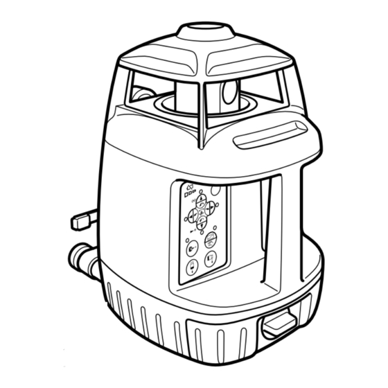
Nomenclature and Functions RL-VH3G/A/B Floor mount Laser emitting window (Floor mount is supplied as an Optional Beam aperture accessory for RL-VH3B) Rotary head Wall mount/dismount lever (Only used for wall mount) Handle Screw for tri- pod W5/8 Panel Leveling screw... - Page 15 Wall mount model-1C Wall mount model-2C Wall mount hole Clamp lever Clamp lever Mount position control line Elevation clamp knob Traveling stage Wall mount hole Laser mounting screw Alignment target Magnetic Scanning Target Magnet Datum line Index Index The blue target is for RL- Index VH3G and the red target is Detector...
- Page 16 Panel RL-VH3A Circular level vial for vertical operation Battery remaining Scan mode Leveling lamp Power switch Grade adjustment Arrow keys Laser pointing Manual focus key Speed control Plumb beam key Laser sensor mode Auto/manual Grade Auto/manual leveling control Auto/manual Alignment Manual mode lamp...
- Page 17 Circular level vial for RL-VH3B vertical operation Scan mode Battery remaining Leveling lamp Power switch Grade adjustment Arrow keys Laser pointing Plumb beam key (Vertical operation Speed control only) Laser sensor mode Auto/manual Grade Auto/manual Alignment Auto/manual leveling control Manual mode lamp...
- Page 18 RL-VH3G Circular level vial for vertical operation Scan mode Battery remaining Leveling lamp Power switch Grade adjustment POWER Arrow keys Laser pointing STOP Manual focus key Speed control MANU Plumb beam key High power mode Auto/manual Grade Auto/manual leveling control...
- Page 19 Arrow keys Y2, Y1 key functions • Use to select either Y1 or Y2 direction in auto slope. (Horizontal rotation only) • Focussing the laser in manual focussing mode. • Selecting a direction the beam should move to scan the floor target in auto line control mode.
-
Page 20: Preparation For Use
Horizontal Rotation Set the instrument on any smooth surface that is within ±5° of true level. The RL-VH3G/A/B auto- level system will not function if the unit is placed more that 5° out of level. For best operation, it is recommended that it be mounted to a tripod or the Topcon Wall Mount Model 2C (provided). -
Page 21: Using Plumb Beam (Rl-Vh3B Has Vertical Plumb Beam Only)
Vertical Rotation Place the instrument on its back as shown in the illus- Vertical tration. circular vial Turn the leveling screw on the instrument until the bub- ble is centered in the circular level vial. Leveling screw Using Plumb beam (RL-VH3B has vertical plumb beam only) You can set the instrument using with the plum laser for centering. -
Page 22: Battery Warning Indicator
Battery Warning Indicator The Battery warning indicator will be shown for several minutes when the instrument is pow- ered ON or when the battery level changes. Continuous Battery is sufficient. The power is low, but laser is still usable. (Blinking continues until batteries are Blinking dead.) Dead batteries. - Page 23 To turn OFF the auto-leveling function (manual mode), press the Auto-Manual leveling con- trol pad twice in quick succession. The manual mode indicator light will illuminate. The instru- ment can be positioned in any direction and the laser beam remains on and the head will rotate.
-
Page 24: Operation
"track" the target as it is moved in its path. Scanning mode is the default operating mode for the RL-VH3G/A/B. Each time the instru- ment is turned on, it is in scanning mode. To change when operating, press the Scan Mode Pad. -
Page 25: Continuous Scan
To stop scanning, remove target from beam path. Note • The target must be in the upright position for horizontal scanning use (magnet on top). Continuous scan (Scan width can be "Drawn" and held for "Hands free" opera- tion) Place target in beam path and hold for a moment. The scanning beam will hesitate, then start again. -
Page 26: Auto Focus (Rl-Vh3A/G Only)
Auto Focus (RL-VH3A/G Only) When a target is used, the beam will focus automatically at the target. Manual Focusing (only for RL-VH3A/G) It is also possible to focus manually with operating keys. Press the manual focus key. The mode changes to manual focussing mode. The focus distance remotes. -
Page 27: Changing Rotation Speed
Changing rotation speed Press either Speed Control pad to change rotation Press the rotation speed keys to speed. The right pad increases the rotation speed. increase or decrease rotation The left pad reduces the rotation speed. speed. Laser Pointing Mode (stop) Laser pointing This mode stops rotation and allows the laser beam to be pointed by manually rotating the head. -
Page 28: Laser Sensor Mode (Rl-Vh3A/B Only)
For long range or outdoor applications, the instrument can be used with an optional electronic laser sensor. Laser sensor mode pad The Topcon models LS-70B or LS-70A are recom- mended. Press the Laser Sensor Mode Pad. The beam rotates at 600 rpm in this setting. -
Page 29: Height Alert Function
The Height Alert function is now inactive. To re-activate, turn unit off and repeat step 1. High Power Mode (RL-VH3G Only) Pressing the high power mode key, the laser power will change alternately. -
Page 30: Setting Slopes
Setting Slopes The laser beam can be sloped in either the X or Y axis (single slope) or both axes (com- pound slope). Using the Slope Control pads (see page 12 ), the beam can be electronically raised or lowered 5 degrees above or below the inclination of the instru- Inclination of the instrument... - Page 31 Setting automatic grade using the alignment target Arrow keys Grade setting direction Auto/manual grade How to set slope Single axis setting Turn the instrument on by pressing the power control pad. Auto-leveling will start. Press the Auto/manual grading pad after auto-leveling is complete. The green Auto/man- ual Grade LED will light and the 4 red of arrow key LEDs will flash.
- Page 32 For Dual axes setting Press another arrow key for the second direction in less than 4 seconds after pressing the key for the first direction. (before the laser starts scanning in the first direction, The key LED for the second direction selected will stop flashing). The laser beam will pre-scan in each direction to show the directions set.
- Page 33 Place the target in the scanning beam so the beam travels in the direction of desired slope. The scanning beam will "look" for the center of the target. When the beam comes to the center of the target, the scanning width will narrow, and the beam will automatically focus.
- Page 34 Setting Manual Grade It is also possible to set up slope manually. This can be used to increase or decrease grade already set in the laser. Arrow keys Grade setting direction Auto/manual grade Turn the instrument on by pressing the power control pad.
- Page 35 The manual mode lamp will light. If you want to set a compound slope, repeat steps 2 and 3 for next axis. The LED of the second direction selected will turn on. To cancel slope settings Press the Manual Mode pad. The instrument returns to auto-leveling mode. Operating range error The range of the grade setting is within ±5 degrees.
-
Page 36: Vertical Beam Alignment
Vertical Beam Alignment Vertical Set-Up: Plumb finder mode Vertical level Provides a plumb laser spot below the rotating head vial to aid in laser set-up over an initial control point. This mode is used only for vertical set-up. Rotate forward foot out 180°, and center it on the control point. - Page 37 Auto Line Control: Smart Line mode This mode provides one person alignment to a far control point. There are two operating methods shown as follows; 1: Operation by keys at the laser 2: Operation at the alignment target side Operation by keys at the laser Center the alignment target on the far control point.
- Page 38 Press either the Y1 or Y2 key to move the scanning beam toward the center of the target. The beam will begin to move, and will align to the center of the target automatically. When the beam reaches the center of the target, the scanning width will narrow, and will automatically focus.
- Page 39 Operation at the alignment target side Press the Auto/manual alignment key. The green Auto/manual alignment key LED will light. Press either the X1 or X2 key to set scanning for the side of the laser that has the target. The laser starts scanning and the selected key's LED will flash. Center the alignment target on the far control point, passing it slowly through the beam.
- Page 40 * The beam can now be moved manually for precise alignment on the control point. Refer to page 39 “Fine movement of the beam after completing alignment”. Operating range error The range of line control is ±5 degrees. When the range has been exceeded, the red LEDs will flash alternately and the rotary head will return to within 3 degrees of 0°.
- Page 41 Fine movement of the beam after completing alignment Fine movement of the beam will be possible after completing the alignment. Move the beam slightly to the right or left by moving the target to the right or left. The beam will move as follows: The scanning laser moves toward the center direction of the target in this part.
- Page 42 Manual Line Control (manual vertical beam alignment) It is also possible to align the laser manually (without the alignment target). Manual alignment is possible from the following modes; Change rotation speed, Laser pointing, Level sensor, Scanning and Plumb finder. Set the alignment target centered on the far control point. Press the Auto/manual alignment key twice.
- Page 43 Operating range error The range of line control is ±5 degrees. When the range has been exceeded, the red LEDs will flash alternately. Press X1 or X2 key to cancel the error and set up the instrument again.
-
Page 44: Setting 90° Vertical Layouts
Setting 90° Vertical Layouts Move the front floor mount leg to its stored 59mm position. Turn the rear floor mount leveling screws to bring the bubble to the center of the vertical level vial. Press the Power Control key to turn unit on. When auto-leveling is complete, the beam will be emitted. - Page 45 The rotating axis of the laser is directly over the center of the front floor mount leg in its stored position. Therefore the beam will rotate forward of the control point when the laser is rotated on the front floor mount leg. The Off-set however is constant (59mm) from the rotation axis to the beam, so marking a control point 59mm behind the actual control point will make set-up easy and accurate.
-
Page 46: Operational Example
Operational Example... -
Page 47: Maintaining Power Sources
Maintaining Power Sources How to replace dry batteries Remove the battery cover by turning the battery compartment lock to “OPEN”. Remove the old batteries and replace with four (4) new “D” cell alkaline batteries making sure each is placed in the proper direction as indicated. Replace the battery cover (DB-49) and turn the knob to “Lock”. - Page 48 Charging Plug the AC/DC converter (AD-9B or AD-7C) into the DB-49C battery holder. Insert the converter receptacle in an outlet (AD-9B is for AC120V, AD-7C is for AC230V) Complete charging by unplugging the con- verter connector from the DB-49C battery holder after approximately 9 hours.
- Page 49 Note: 1) It can be charged while using the laser. 2) The BT-49Q rechargeable battery can be charged when removed from laser. 3) When the BT-49Q rechargeable battery is taken off from the DB-49 battery holder, the instrument can be used with dry batteries instead of BT-49Q. Note: 1) Recharging should take place in a room with an ambient temperature range of 10°C to 40°C (50°F to 104°F).
-
Page 50: Checking And Adjusting
The Horizontal Calibration and Vertical Calibration can be easily checked and, in most cases, adjustments can be made by the user. Horizontal Rotation Cone can be checked by the user, if an error is found, adjustments must be made by a Topcon service facility. Attaching the calibration decals Before calibration, attach the calibration decals to the instrument as shown below. -
Page 51: Horizontal Calibration
Horizontal Calibration (1)Checking Calibration Instrument as seen from above 50m (160feet) Target Wall Panel side Set up a tripod 50m(160ft) from a wall. Mount the instru- ment on the tripod, facing the X1 toward the wall. Turn the unit on and allow auto-leveling to complete. Place a piece of paper on the wall. - Page 52 Turn the unit on again and allow auto-leveling to complete. If less than 5mm( 0.2 inches) No calibration Necessary Make a new mark (Mb) where the laser beam strikes the paper. X1 laser beam Measure the distance between the first mark (Ma) and the second mark (Mb).
- Page 53 • If the calibration is greater than the adjustment allows, the error LED will start flashing. If this occurs, contact your Topcon dealer. For Y axis calibration, turn the unit as instructed in step 1 above then press the X/Y Axis Selection pad.
-
Page 54: Horizontal Rotation Cone Error
Measure the distance between the first and second marks on each wall. If the difference between each set of marks is less than 4mm (5/32 of an inch), no error exists. Note • If the error is greater than 4mm ( 5/32 of an inch), contact your Topcon dealer. -
Page 55: Vertical Calibration (Upward)
Vertical Calibration (Upward) Perform the following check after completing "Horizontal Calibration" on the previous page. (1) Checking RL-VH3G/A about 20 m about 20 m (66ft) (66ft) Set up the instrument half way between 2 Wall walls a minimum of 40m away from each Wall other. - Page 56 Compare the two measurements dHa and dHb. If the difference between the two mea- surements is less than 2.5mm ( 1/10 of an inch), no adjustment is necessary. Otherwise, adjust as follows. (2)Checking RL-VH3B Set up the instrument half way between 2 walls a minimum of 40m away from each other. (The instrument can be facing either direction X or Y.
- Page 57 Without moving the position of the front foot, pivot the instrument so the rotary head is now facing wall B. Mark where the split beam emitted from the top of the rotary head strikes wall B (Hb). Measure the distance (dHb) between marks Mb and Hb.
- Page 58 (3) Adjusting Calibration for RL-VH3A/B/G Turn the unit off by pressing the [START] about 20 m about 20 m pad once. Confirm that unit has shut off (66ft) (66ft) before beginning the following procedure. (In Wall Wall step 2 and 3, use of optional RC-30 remote control can be helpful.
- Page 59 When the flashing stops, the vertical calibration adjustment is made and power is turned off automatically. Note • If the calibration is greater than the adjustment allows, the error LED will start flashing. If this occurs, contact your Topcon dealer. Repeat the checking procedure to confirm proper calibration has been made.
-
Page 60: Laser Beam (Downward)
Turn the power switch on again and level the instrument. Measure the distance from datum position on wall B. When the difference between measurements is less than 2.5mm, the laser position is pre- cise enough. Note; If difference exceeds 2.5 mm, contact your dealer or Topcon. -
Page 61: Storage Precautions
Storage Precautions Always clean the instrument after use. Use a clean cloth, moistened with a neutral detergent or water. Never use an abrasive cleaner, ether, thinner benzene, or other solvents. Always make sure instrument is completely dry before storing. Dry any moisture with a soft, clean cloth. -
Page 62: Standard / Optional Accessories
Standard / Optional Accessories Wall mount-2C This is used to attach the instrument to wall molding or metal studs. Grip wall angle/mold- ing or screw to studs and tighten the attachment screw securely. Mount position control line To be matched with lower mount side Wall mount hole Clamp handle Traveling stage... - Page 63 Note :Always tie a ceiling wire through the laser handle and secure to a fixed object as a safety precaution to prevent the laser from getting knocked or loosened from its position and to the floor. How to mount /dismount the instrument 1)Set the floor mount hole on the travel- ing stage hook and slide the instrument...
- Page 64 Laser sensor holder model 5 Wall mount model-1C (For RL-VH3B) Clamp lever Clamp knob Elevation clamp knob Laser sensor holder model 5 Laser mounting screw Laser sensor Holder Model 5 allows the laser sensor to be moved up or Clip on target down on the staff by squeezing the spring-loaded clamp Used for gripping girder or ceiling on its back side without removing the sensor from the staff.
- Page 65 LS-70B Laser Sensor LS-70A Laser Sensor Beam receiving window Beam receiving window Indicator Indicator Index Index Index Index Detective precision switch Buzzer sound Two leveling precision switch options are available, normal precision and (Quite/Loud/OFF) high precision. By Power switch pressing this switch, the precision options are switched alternately.
- Page 66 If laser remains in standby mode for for RC-30 2 hours, laser will turn off automatically. Mode switch control Stop beam control (RL-VH3G does not have Laser sensor mode.) Speed control Manual focus control ( Only for RL-VH3A/G) Alignment control...
- Page 67 Scan mode / Laser sensor mode / Laser pointing mode. control Manual focus Laser beam can be focused manually. (RL-VH3G/A models only) control X/Y axis selection Sets slope mode by pressing for more than three seconds. Select X or Y axis for manual grading.
- Page 68 How to set remote control communication channel The same channel must be set on the RL-VH3G/A/B and the RC-30 remote controller. RL-VH3C Remove the battery cover by turning the battery compartment lock to “OPEN”. Turn the channel switch to set a channel by using with a small straight screw- driver.
-
Page 69: Specifications
Note1)The distance of visible laser beams are not constant due to the brightness of the surroundings. Using with LS-70A/70B Diameter 2 to 500 m ( 6.6 to 1640.5ft) (RL-VH3A/B Only) Light source L.D (Visible laser) Wave length 633nm (RL-VH3A/B) 532nm (RL-VH3G) - Page 70 Rotation speeds RL-VH3A/B Changeable : 30 to 600 r.p.m. Level sensor mode : 600 r.p.m When scanning : 80 r.p.m RL-VH3G Changeable : 30 to 300 r.p.m. When scanning : 80 r.p.m Scanning width Maximum 180° Line control Operation distance 3 to 50 m ( 9.8 to 164ft)
- Page 71 Continuous operating time (+20°C) Alkaline manganese dry batteries RL-VH3A/B Approx. 40 hours RL-VH3G Approx. 30 hours Rechargeable battery BT-49Q RL-VH3A/B Approx. 30 hours RL-VH3G Approx. 20 hours Flat and dome head type, 5”/8 × 11threads Tripod screw Operating temperature -20°C to +50°C (-4°F to +122°F) Dimensions 214(L) ×...
- Page 72 (32.8ft) (98.4ft) (164ft) Width of visible Horizontal, Vertical 0.5mm 1.0mm 1.5mm 3.5mm 5.0mm beam *Note (When scanning) Diameter of Diameter of laser RL-VH3G 0.5mm 1.0mm 2.0mm 5.0mm 8.5mm visible beam beam spot 0.5mm 1.0mm 2.0mm 6.0mm 10.5mm RL-VH3A/B *Note (Upward) Diameter of laser beam spot 1.5mm...
-
Page 73: Error Indication
Height alert Turn OFF and ON again. Internal memory err. Turn OFF and ON again. Mechanical err. Laser beam blinks. Turn OFF and ON again. If errors still persist after attempting to clear them, contact your dealer or Topcon. - Page 75 5758 West Las Positas Blvd., Pleasanton, CA 94588, U.S.A. HEAD OFFICE Phone: 925-460-1300 Fax: 925-460-1315 www.topcon.com Topcon House Kennet Side, Bone Lane Newbury Berkshire RG14 5PX TOPCON CALIFORNIA U.K. Phone: 001-44-1635-551120 Fax: 001-44-1635-551170 3380 Industrial Blvd, Suite 105, West Sacramento, CA 95691, TOPCON SINGAPORE PTE.
Need help?
Do you have a question about the RL-VH3G and is the answer not in the manual?
Questions and answers