Table of Contents
Advertisement
Advertisement
Table of Contents

Related Manuals for Topcon RL-VH4DR/G2


Summary of Contents for Topcon RL-VH4DR/G2
- Page 1 INSTRUCTION MANUAL ROTATING LASER RL-VH4DR/G2 31375 90050...
-
Page 3: Foreword
Thank you for purchasing the Topcon RL-VH4DR/G2 Rotating Laser. It is one the world’s most advanced lasers. To quickly and effectively use the RL-VH4DR/G2, please read these brief instructions carefully, and keep them in a convenient location for future reference. -
Page 4: Safety Information
Safety Information In order to encourage the safe use of products, to prevent damage to properties, and to prevent any danger to the operator and to others, important warnings are placed on the products and inserted in the instruction manuals. We suggest that everyone understand the meaning of the following displays and icons before reading the “Safety Cautions”... -
Page 5: Safety Cautions
There is a risk of fire, electric shock or physical harm if you attempt to disassemble or repair the instrument yourself. This is to be carried out by TOPCON or an authorized dealer, only! Laser beam can be dangerous, and can cause eye injury if used incorrectly. - Page 6 CAUTION Use of controls or adjustment or performance of procedures other than those specified herein may result in hazardous radiation exposure. Let the laser beam reach the aimed object or the target without anybody else in the laser beam path. When operating in an open area, avoid radiating laser beam at eye level.
-
Page 7: User
User Wear the required protectors (safety shoes, helmet, etc.) when operating. Exceptions from Responsibility 1) The user of this product is expected to follow all operating instructions and make periodic checks of the product’s performance. 2) The manufacturer, or its representatives, assumes no responsibility for results of a faulty or intentional usage or misuse including any direct, indirect, consequential damage, and loss of profits. -
Page 8: Laser Safety
(IEC Publication 60825-1) provided on the safety standards for laser beam. As per the said standard, RL-VH4DR/G2 standard model is classified as “Class 3R (IIIa) Laser Products”. These are simple products to operate and do not require training from a laser safety officer. -
Page 9: Table Of Contents
Contents Foreword .......................... 1 Handling Precautions....................1 Safety Information...................... 2 Safety Cautions ......................3 User ........................... 5 Exceptions from Responsibility.................. 5 Laser Safety....................... 6 Contents ........................7 Standard System Components.................. 9 Nomenclature and Functions ..................10 Preparation for Use ......................12 Battery Installation .................... - Page 10 Nomenclature ......................24 Description of RC-40 functions and Error ..............25 How to set remote controller communication channel ..........27 Maintaining Power Sources ................... 28 Replacing dry batteries .................... 28 Checking and Adjusting ....................29 Horizontal Calibration ....................30 Horizontal Rotation Cone Error................34 Vertical Calibration....................
-
Page 11: Standard System Components
Standard System Components RL-VH4DR/G2 Instrument............1pc. Remote Controller RC-40 .............1pc. Battery unit ................1set AA size dry cell battery .............2pcs. Carrying case ...............1pc. Calibration decals ..............1set Instruction manual ..............1vol. • Please make sure that all of the above items are in the box when you unpack. -
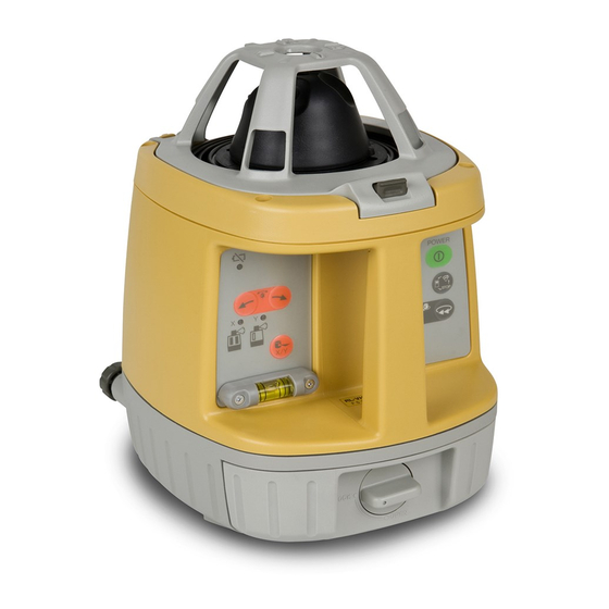
Page 12: Nomenclature And Functions
Nomenclature and Functions RL-VH4DR/G2 Laser emitting window Beam aperture Rotary head Magnetic Scanning Target Head protector Magnet Lock button Handle Datum line Index Index Control panel Reflectors Lines may appear on the reflector strips. Leveling screw They are part of normal manufacturing process and do not effect performance. -
Page 13: Control Panel
Control Panel Leveling lamp Flashing: Laser is leveling Plumb beam On: Auto-leveling is completed (RL-VH4DR/G2 remote controller model has standby mode) Low battery alert Power switch Mode switch control Alignment Laser mode is switched control alternately as follows. Scan mode Head rotates slowly, searching for Magnetic Scanning Target. -
Page 14: Preparation For Use
5° out of level. For best operation, it is recommended that it be mounted to a tripod or the Topcon Wall Mount Model 1D. Slope can be set in both axes, X and Y. See “Setting Slopes”... - Page 15 Vertical Rotation Place the instrument on its back as shown in the illustration. Level vial Turn the leveling screw (s) underneath the instrument until the bubble in the level vial on the operational panel is centered. Battery Warning Lamp Flashing : The power is low ON Solid : Dead batteries Replace the batteries with new ones.
-
Page 16: Operation
Operation Scanning Mode In scan mode, the laser rotates slowly, “searching” for the Magnetic Scanning Target. When the target is properly placed in the beam path, the laser beam will scan rapidly back and forth on the target and “track” the target as it is moved in its path. To change to scanning mode when operating, press the mode switch control key (see page 11). -
Page 17: Continuous Scan
Continuous scan (Scan line length can be “Drawn” and held for “Hands-free” operation) Place target in beam path and hold for a moment. The scanning beam will hesitate, then start again. When the target is now removed the beam will continue to scan automatically. To change the length of the scanning line, move the target left or right after the initial scan hesitation and the scanning line length will increase until the target is removed. -
Page 18: Plumb Beam Mode
Plumb Beam Mode You can set the instrument using with the plumb beam for centering. To cancel the plumb beam mode, press any other key (except the plumb beam switch and the power switch). Plumb beam for vertical operation This mode can be used with the Remote Controller RC-40. -
Page 19: Level Sensor Mode
For long range or outdoor applications, the instrument can be used with an optional electronic level sensor. The Topcon LS-80G model is recommended. Press the mode switch control key to select level sensor mode. The beam rotates at 300 rpm in this setting. -
Page 20: How To Remove/Install Head Protector
How to Remove/Install Head Protector When the head protector post blocks the laser beam and interferes with operation, remove the head protector from the instrument. How to Remove Press the lock button to release the lock. Set the angle of the head protector to approximately 45°. Post Lock button Pull the head protector in the direction of the arrow. - Page 21 How to Install Insert the head protector pin into the groove of the instrument until you feel it click. Pin, Groove Bring down the head protector until you hear a clicking sound. Check that the head protector is securely locked.
-
Page 22: Height Alert Function
Height Alert function When auto-leveling and height alert function are active, this function prevents the instrument from operating if it is disturbed (after the laser beam emits for one minute). This helps insures accurate control. If the height or inclination of the instrument changes, the height of instrument should be verified and re-established if necessary. -
Page 23: Setting Slopes
Setting Slopes The laser beam can be manually sloped in either the X or Y axis (single slope) or both axes (compound slope). With the inclination of the instrument as the standard, laser beam can be sloped within the range of ±5°... - Page 24 How to set slopes Turn the instrument on by pressing the Power control key. Auto-leveling will start. Press the X/Y axis selection key once (see page 11). The X axis lamp will flash. To change to Y axis, press the X/Y key once again. Pressing the X/Y key toggles between X and Y axis selection.
- Page 25 Line Control (manual vertical beam alignment) Turn the leveling screw and position the bubble of the level vial on the control panel in the center. Press the Power control key to turn unit on. When auto- leveling is complete, the laser beam will be emitted. Press the plumb beam key to select the plumb beam mode.
-
Page 26: Rc-40 Remote Controller
RC-40 Remote Controller Nomenclature Transmission lamp Battery warning lamp for RC-40 Mode switch control Sleep mode X/Y axis selection Alignment control RC-40 X/Y axis lamp Speed control When both the right and left keys are pressed simultaneously, the plumb beam mode will activate. Strap attachment hole Remote Controller •... -
Page 27: Description Of Rc-40 Functions And Error
Description of RC-40 functions and Error Sleep mode To set up (or cancel) the rotating laser to the sleep mode, press the sleep mode key for three seconds or longer. (In Sleep mode, the leveling lamp of the rotating laser will flash.) Laser turns off if standby mode continues for two hours. - Page 28 (Radio transmission performance is lower near the ground.) With the RC-40, both the X and Y axes lamps will flash red simultaneously when more than one RC-40 or RL-VH4DR/G2 are used, and also when similar wireless signals (wireless LAN, etc.) are being transmitted.
-
Page 29: How To Set Remote Controller Communication Channel
How to set remote controller communication channel The same channel (1 to 9) must be set on the RL-VH4DR/G2 and the RC-40 remote controller. RL-VH4DR/G2 Remove the battery cover by turning the battery compartment lock to “OPEN”. Turn the channel switch to set a channel by... -
Page 30: Maintaining Power Sources
Maintaining Power Sources Replacing dry batteries Remove the battery cover by turning the battery compartment lock to “OPEN”. Remove the old batteries and replace with new 4 D size × dry cell batteries (alkaline) making sure each is placed in the proper direction as indicated. Replace the battery cover and turn the knob to “Lock”. -
Page 31: Checking And Adjusting
The Horizontal Calibration and Vertical Calibration can be easily checked and, in most cases, adjustments can be made by the user. Horizontal Rotation Cone can be checked by the user, but if an error is found, adjustments must be made by a Topcon service facility. Attaching the calibration decals Before calibration, attach the calibration decals to the instrument as shown below. -
Page 32: Horizontal Calibration
Horizontal Calibration (1) Checking Calibration 30 m (98 feet) Instrument as seen from above Target Wall Panel side Set up a tripod 30 m (98 ft) from a wall. Mount the instrument on the tripod, facing the X1 side toward the wall. Turn the unit on and allow auto-leveling to complete. - Page 33 Turn the unit on again and allow auto-leveling to If less than 6 mm (.23 inches) complete. No calibration Necessary Make a new mark (Mb) where the laser beam strikes X1 laser beam the paper. Measure the distance between the first mark (Ma) X2 laser beam and the second mark (Mb).
- Page 34 (2) Adjusting Calibration If the distance between either set of marks is more than 6 mm (1/4 of an inch) but less than 25 mm (1 inch), turn the unit off by pressing the [START] key once and use the following procedure to calibrate the laser.
- Page 35 If the calibration is greater than the adjustment allows, the error LED will start flashing. NOTE (See “Error Code” on page 51) If this occurs, contact your Topcon dealer. When the laser beam is difficult to see, it can be adjusted in the Laser sensor mode or the Laser pointing mode.
-
Page 36: Horizontal Rotation Cone Error
Measure the distance between the first and second marks on each wall. If the difference between each set of marks is less than 3 mm (1/8 of an inch), no error exists. NOTE If the error is grater than 3 mm (1/8 of an inch), contact your Topcon dealer. -
Page 37: Vertical Calibration
Vertical Calibration Perform the following check after completing “Horizontal Calibration” on the previous page. (1) Checking about 15 m about 15 m (49 ft) (49 ft) Set up the instrument half way between two Wall Wall walls a minimum of 30 m (98 ft) apart. (The instrument can be facing either direction X or Y. - Page 38 Without moving the position of the front foot, pivot the instrument so the rotary head is now facing wall B. Mark where the split beam emitted from the about 30 m (98 ft) top of the rotary head strikes wall B (Hb). Measure the distance (dHb) between marks Mb and Hb.
- Page 39 (2) Adjusting Calibration Turn the unit off by pressing the [START] key once. Confirm that unit has shut off before beginning the following procedure. (In step 2 and 3, optional RC-40 remote controller is helpful.) Without moving the unit, press the [ENTER] and [START] keys simultaneously. Press either the right or left key on the Alignment Control key to move the laser beam up or down on wall B until the measurement for the distance dHb is the same as the measurement dHa on wall A.
- Page 40 (The [ENTER] key for the RC-40: The same mark as the [ENTER] key for the instrument.) If the calibration is greater than the adjustment allows, the error LED will start NOTE flashing. If this occurs, contact your Topcon dealer. Repeat the checking procedure to confirm proper calibration has been made.
-
Page 41: Standard / Optional Accessories
Standard / Optional Accessories Detective beam indication LED LS-80A / 80B / 80G / 90 Level Sensor (LS-90) Indicator Power switch (LS-80A / 80G / 90) Beam receiving window Indicator Detective precision switch Two on-grade precision options are Index available, normal precision and high precision. - Page 42 No audio signal is generated for this warning. The warning signal *1 and *2 will function only if RL-VH4DR/G2 Alert Signal function [COM] is active. Alarm detection at the level sensor can be canceled by turning off the level sensor switch while pressing the buzzer sound switch.
- Page 43 Detective range (LS-80A / 80B / 80G) (LS-90) ±0.5mm (1mm width) ±2mm (4mm width) LED : Lights in the center ±5mm (10mm width) LED : Flashes alternately ±10mm (20mm width) LED : Flashes rapidly ±15mm (30mm width) LED : Flashes more than ±15mm (more than 30mm width) LED : Flashes slowly...
- Page 44 Replacing Battery Keep pushing the battery cover in 1 direction, and then try to slide the cover in 2 direction. The cover does not move but it will be open. Take out the battery and place a new one into the battery box. Press the lid down and click to close.
- Page 45 Wall Mount 1D Level sensor holder model 6 1 5 4 1 5 3 Clamp lever 1 5 2 1 5 1 Laser Mounting 1 5 0 Clamp knob screw 1 4 9 1 4 8 1 4 7 1 4 6 H O L D E R -6 1 3 1 1 3 9...
- Page 46 Red flashing: BT-63Q protection feature is working automatically. RL-VH4DR/G2 can be used in this state. Automatic protection feature; In case of overcharge or high or low temperature state exceeding charging range, charging will be stopped or changed to protect battery.
-
Page 48: Storage Precautions
1) The Ni-MH BT-63Q rechargeable battery can be charged while using the laser. 2) The DB-70 dry cell battery holder cannot be used to charge the BT-63Q Ni-MH battery pack. Use the DB-70C charging battery holder instead. Storage Precautions Always clean the instrument after use. Use a clean cloth, moistened with a neutral detergent or water. -
Page 49: How To Store
How to Store LS-80A / 80B / 80G / 90 RL-VH4DR/G2 D size dry cell battery RC-40 AD-13 Level sensor holder model 6 Wall Mount 1D Magnetic Target AA size dry cell battery... -
Page 50: Specifications
Specifications RL-VH4DR/G2 Accuracy Horizontal : ±20" Vertical : ±20" Auto-leveling range : ±5° Measuring range (Diameter) : RL-VH4DR : Using with LS-80A / 80B / 90 : 2 m (6.6 ft) to 300 m (984 ft) (Rotation speeds 300 r.p.m) RL-VH4G2 : Using with LS-80G : 2 m (6.6 ft) to 300 m (984 ft) - Page 51 Remote controller RC-40 Operating range (Radius) : 100m or more (Condition: set the RL-VH4DR/G2 on a tripod. Use the RC-40 at 1.2 meters above ground.) : 30m or more (Condition: set the RL-VH4DR/G2 on ground with vertical operation. Use the RC-40 at 30cm above ground.) Power supply : 2×AA size dry cell batteries (alkaline)
- Page 52 LS-80A / 80G (Back side display area) LS-80B Detective range : 50 mm (2.0 in) Detective range : 50 mm (2.0 in) Detective precision Detective precision High precision : ±1 mm (±0.04 in) High precision : ±1 mm (±0.04 in) Normal precision : ±2 mm (±0.08 in) Normal precision : ±2 mm (±0.08 in) Detective beam indication...
- Page 53 LS-90 (Back side display area / LED / Plate level) Detective range : 50 mm (2.0 in) Detective precision High precision : ±0.5 mm (±0.02 in) Normal precision : ±2 mm (±0.08 in) Detective beam indication : Liquid crystal (Both sides) / Buzzer / LED Power source : 2×AA size dry cell batteries Power voltage...
-
Page 54: Error Code
Error Code Use the table below to determine operation errors indicated by blinking lamps on the control panel. If corrective action listed does not correct error, please contact your local Topcon dealer. Lamp Indication Error Code Corrective Action Lamp A, B and C blink Auto-leveling range error Correct tilt of the instrument until it less than 5 degrees. - Page 55 2008 TOPCON CORPORATION ALL RIGHTS RESERVED...
- Page 56 7400 National Drive, Livermore, CA 94551, U.S.A. Topcon House Kennet Side, Bone Lane, Newbury, Berkshire RG14 5PX U.K. Phone: 925-245-8300 Fax: 925-245-8599 www.Topconpositioning.com Phone: 44-1635-551120 Fax: 44-1635-551170 survey.sales@topcon.co.uk laser.sales@topcon.co.uk 3380 Industrial Blvd, Suite 105, West Sacramento, CA 95691, U.S.A. Phone: 916-374-8575 Fax: 916-374-8329 Blk 192 Pandan Loop, #07-01 Pantech Industrial Complex, Singapore 128381 Phone: 65-6778-3456 Fax: 65-6773-6550 www.topcon.com.sg...
Need help?
Do you have a question about the RL-VH4DR/G2 and is the answer not in the manual?
Questions and answers