Table of Contents
Advertisement
Quick Links
Advertisement
Table of Contents

Subscribe to Our Youtube Channel
Related Manuals for Leica F12 I


Summary of Contents for Leica F12 I
- Page 1 Leica F12 I User Manual...
-
Page 2: Table Of Contents
Focusing Arm: Configuration 1 for Table Inspections Care and Maintenance Focusing Arm: Configuration 2 for Table Inspections Troubleshooting Focusing Arm: Configuration 3 for Table Inspections Technical Data Focusing Arm: Configuration 1 for Wall Inspections Dimensions Alternative: Variable Focusing Arm Leica F12 I Floor Stand Manual... -
Page 3: General Instructions
General Instructions Safety Concept The Leica F12 I series can be used in clean rooms Servicing Before installing the Leica F12 I floor stand or without any problems. Repairs may only be carried out by Leica Ϙ using it for the first time, please read the "Safety Microsystems-trained service technicians. -
Page 4: Safety Concept
Safety Concept The Leica F12 I is shipped with an interactive You can combine individual system articles CD-ROM, where you can find all relevant user with articles from external suppliers (e.g. cold manuals. Keep it in a safe place, and readily light sources, etc.). -
Page 5: Symbols Used
Instrument malfunctions and damage. Ϙ to provide clarity. Warning of hazardous electrical voltage This symbol indicates especially important information.Failure to observe can cause the following: Hazards to persons! Ϙ Instrument malfunctions and damage. Ϙ Leica F12 I Floor Stand Manual... -
Page 6: Safety Instructions
Non-intended use Ensure that: Refer to the "Safety Concept" brochure. Ϙ Installation location The Leica F12 I is operated, maintained and Ϙ Refer to the "Safety Concept" brochure. Ϙ repaired only by authorized and trained The instruments and accessories described Electrical components must be placed at personnel. - Page 7 Transport Refer to the "Safety Concept" brochure. Ϙ Always use the original packaging for ship- Ϙ ping or transporting the Leica F12 I. Legal requirements In order to prevent damage from vibrations, Refer to the "Safety Concept" brochure. Ϙ Ϙ...
-
Page 8: Leica F12 I
Leica F12 I Floor Stand Leica F12 I Floor Stand Manual... -
Page 9: Introduction
Thank you for choosing our products. We hope that the Leica F12 I is a flexible, sturdy and cost- that you will enjoy the quality and performance effective solution. -
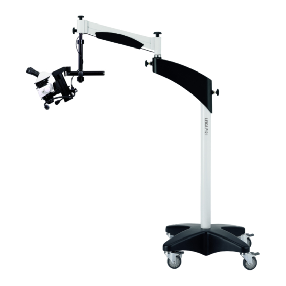
Page 10: Overview (Sample Configuration)
Castors with footbrakes Cable holder Small horizontal arm Large horizontal arm Storage compartment for power pack 10 Large vertical column 11 Brake knob for locking the verti- cal position 12 Rotary knob for balancing 13 Flex-arm Leica F12 I Floor Stand Manual... -
Page 11: Installation
Installation Leica F12 I Floor Stand Manual... -
Page 12: Pedestal And Large Vertical Column
The pedestal and the large vertical column are very heavy. Always request assistance for assembly! Assembly 1. Move the pedestal to a flat, level surface and lock all 4 footbrakes. 4. Cover the screw holes using the cover caps. Leica F12 I Floor Stand Manual... -
Page 13: Large Horizontal Arm And Flex-Arm
The large horizontal arm does not need arm are very heavy. Always request 1. Place the large horizontal arm onto the to be fastened, because the weight of the assistance for assembly! large vertical column. structure ensures a secure connection. Leica F12 I Floor Stand Manual... -
Page 14: Small Vertical Column: Assembly
Small Vertical Column: Assembly The small vertical column connects the Assembly Leica floor stand to the actual micro- 1. Press the small vertical column onto the scope assembly. coupling piece from below. 2. Attach the small vertical column using the 4 Allen screws provided. -
Page 15: Small Vertical Column: Montage
1. Remove the wingscrew from the small hori- hole in the small vertical column. Here, the zontal arm. beveled side must point in the direction of the outer knob. 4. Tighten both locking screws as much as necessary for your work. Leica F12 I Floor Stand Manual... -
Page 16: Small Vertical Column: Height Adjustment
2. Unscrew the safety ring. safety ring loosened. 3. Move the small horizontal arm to the desi- red position. 4. Tighten the safety ring. Leica F12 I Floor Stand Manual... -
Page 17: Focusing Arm: Configuration 1 For Table Inspections
1. Push the holder of the focusing arm from scope could fall onto the specimen! below into the opening of the small hori- zontal arm. 3. Be sure to secure the focusing arm using the screw provided! Leica F12 I Floor Stand Manual... -
Page 18: Focusing Arm: Configuration 2 For Table Inspections
Modify the tilt of the focusing arm and tigh- 1. Push the holder of the focusing arm from ten the locking screw. the front into the opening of the small hori- zontal arm. 2. Unscrew both clamping screws on the focusing arm. Leica F12 I Floor Stand Manual... -
Page 19: Focusing Arm: Configuration 3 For Table Inspections
3. Unscrew both clamping screws on the 5. Tighten the clamping screws on the focu- Assembly focusing arm. sing arm. 1. Push the holder of the focusing arm from above into the opening of the small hori- zontal arm. Leica F12 I Floor Stand Manual... -
Page 20: Focusing Arm: Configuration 1 For Wall Inspections
1. Extend the small horizontal arm far out and the counter-screw and washer provided. tion. push the holder of the focusing arm from above into the opening. 2. Tighten the locking screw. Leica F12 I Floor Stand Manual... -
Page 21: Alternative: Variable Focusing Arm
The assembly steps are identical to those Otherwise it can tip forward abruptly and dest- for the basic focusing arm. roy the specimen! 2. Unscrew the clamping screw. Leica F12 I Floor Stand Manual... -
Page 22: Microscop Installation
Microscope Installation Leica F12 I Floor Stand Manual... -
Page 23: Optics Carrier And Objective
Optics Carrier and Objective Assembly 1. Insert the optics carrier into the focusing 2. Securely tighten the clamping screw. Screw the objective into the optics carrier. arm. Regularly check whether the clamping screw is still tight. Leica F12 I Floor Stand Manual... -
Page 24: Tube And Eyepieces
1. Place the tube onto the optics carrier. tube automatically shifts to the correct 4. Secure the eyepieces using the clamping position when the screw is tightened. screws. Refer to the corresponding manuals for additional information on the individual instruments. Leica F12 I Floor Stand Manual... -
Page 25: Dioptric Correction And Parfocality
The system is now parfocally matched to your eyes. 3. Rotate both eyepieces to the maximum Therefore, all Leica eyepieces are also available value of "+5". with built-in dioptric correction, allowing the 4. Hold one eye closed and rotate the other stereomicroscope to be used without glasses eyepiece in "-"... -
Page 26: Operation
Operation Leica F12 I Floor Stand Manual... -
Page 27: Adjusting The Joint Resistance
Loosen the articulation brakes to make the Ϙ difficult it is to move the arm. corresponding element move more easily. Tighten the articulation brakes to make Ϙ it harder to move the corresponding element. Leica F12 I Floor Stand Manual... -
Page 28: Balancing The Flex-Arm
Never balance the flex-arm over a speci- men. The Leica F12 I is designed for weights between 1.5 kg and 6.5 kg. The correct direction of rotation (lighter/ heavier) is indicated below the rotary knob. -
Page 29: Adjusting The Working Height Of The Microscope
Never adjust the working height over a Adjusting the working height specimen! 1. Carefully release the brake knob on the front end of the flex-arm. 2. Move the microscope to the desired working height. 3. Tighten the brake knob. Leica F12 I Floor Stand Manual... -
Page 30: Safe Transport
For this 1. Position the flex-arm approximately hori- flex-arm together. reason, the Leica F12 I may only be moved with zontal. the flex-arm folded together and locked! 2. Tighten the brake knob for the vertical position lock. - Page 31 7. Lock all four footbrakes. 8. Connect the power cable. For safety reasons, always push the floor stand—never pull it. Leica F12 I Floor Stand Manual...
-
Page 32: Illumination
Illumination Leica F12 I Floor Stand Manual... -
Page 33: (Optional) Leica Led1000 Combi Controller
1 Leica ring illumina- combi controller to the connector piece on tor. the small vertical arm. 3. Connect the power cable to the Leica combi controller and the power pack. Leica F12 I Floor Stand Manual... - Page 34 (Optional) Leica LED1000 Combi Controller (continued) 4. Store the power pack in the storage compartment of the large horizontal arm. For additional information on operating the Leica LED1000 illumination, refer to the manual provided for this instrument. Leica F12 I Floor Stand...
-
Page 35: Leica High-Power Spotlight
The LED of the Leica high-power spot- light becomes only slightly warm during operation. Nevertheless, be sure that the speci- 5. Secure the power cable using the Velcro... -
Page 36: Leica 2-Arm Led Spotlight
The LEDs of the Leica 2-arm LED spot- light become only slightly warm during 4. Install the focusing arm. operation. Nevertheless, be sure that the speci- 5. - Page 37 Appendix Leica F12 I Floor Stand Manual...
-
Page 38: Care And Maintenance
Optical surfaces should be cleaned using Ϙ a lint-free cloth, lens cloth or cotton swab soaked in methanol or a commercially available glass cleaner. Do not use alcohol. Leica F12 I Floor Stand Manual... -
Page 39: Troubleshooting
Gas spring is defective. Have the gas spring replaced by Leica service. The microscope can either not be moved, or The articulation brakes are too tight. Loosen the articulation brakes (see page 27). -
Page 40: Technical Data
500 mm Minimum instrument height (for trans- 1680 mm port) Stand weight Approx. 100 kg (without attachments) Interface to focusing arms/drives: 5/8" (15.8 mm) Interface for illuminators M6 threaded hole for LED1000 combi controller Leica F12 I Floor Stand Manual... -
Page 41: Dimensions
Dimensions Leica F12 I Floor Stand Manual... - Page 42 Dimensions (continued) Leica F12 I Floor Stand Manual...
- Page 43 Dimensions (continued) Leica F12 I Floor Stand Manual...
- Page 44 Dimensions (continued) Leica F12 I Floor Stand Manual...
Need help?
Do you have a question about the F12 I and is the answer not in the manual?
Questions and answers