Table of Contents
Advertisement
Advertisement
Table of Contents

Related Manuals for Leica DM6000 B


Summary of Contents for Leica DM6000 B
- Page 1 Leica DM6000B Leica DM6000M Operating Manual...
- Page 2 Published January 2004 by: Leica Microsystems Wetzlar GmbH Ernst-Leitz-Straße D-35578 Wetzlar (Germany) Responsible for contents: Karin Schwab (Marketing CM, Compound Microscopy, Product Management) Holger Grasse (Safety Officer according to MPG §30) In case of questions, please contact the hotline: Phone...
- Page 3 Leica DM6000B Leica DM6000M Operating Manual...
- Page 4 (in whole or in part) by print, photocopy, microfilm or other method (in- cluding electronic systems) is not allowed with- out express written permission from Leica Microsystems Wetzlar GmbH. The term "Windows" can be used in the follow- ing text without further identification.
-
Page 5: Table Of Contents
8.9 Aperture Diaphragm and DIC Prisms ..........33 Field Diaphragm ........67 6.10 Optional Accessories ....... 34 6.11 Connecting the Leica CTR6000 Electronics Box ..36 6.12 Connecting the Computer ....... 37 6.13 Connection to the Power Supply ... 37... - Page 6 Contents Contrasting Methods 11. Trouble Shooting ........78 for Leica DM6000 B ........68 9.1 Transmitted Light ........68 12. Care of the Microscope ......81 9.1.1 Bright Field ........68 12.1 Dust Cover ..........81 9.1.2 Phase Contrast ....... 69 12.2 Cleaning ............
-
Page 7: Important Notes About This Manual
Therefore, it must be kept and assembled, put into operation or used. taken care of. For the operation of the LeicaScreen and the Software Leica DMControl, please see separate operating manual. Text symbols, pictograms and their meanings: (1.2) Numbers in parentheses, such as "(1.2)", corre- spond to illustrations (in the example, Figure 1, Item 2). -
Page 8: Intended Purpose Of Microscopes
2. Intended Purpose of Microscopes 2. Intended Purpose of Microscopes The Leica DM6000 B microscope, to which this user manual belongs, is designed for biological Caution! routine and research applications. This includes the examination of samples taken from the hu-... -
Page 9: Safety Notes
The responsible Leica affiliate or the main plant in Wetzlar must be consulted when- ever the device is altered, modified or used Caution! in conjunction with non-Leica components that are outside of the scope of this manual. -
Page 10: Electrical Safety
Relative humidity: max. 80% to 30°C wire potential. For connections without a Overvoltage category: ground connector, Leica Service must be Pollution degree: consulted. Supply unit ebq 100* For indoor use only. Supply voltage:... - Page 11 3. Safety Notes Caution! The microscope’s electrical accessory com- ponents are not protected against water. Water can cause electric shock. Caution! Protect the microscope from excessive tem- perature fluctuations. Such fluctuations can lead to the accumulation of condensation, which can damage the electrical and optical components.
-
Page 12: Overview Of The Instrument
4. Overview of the Instrument 4. Overview of the Instrument Specification Leica DM6000 B Leica DM6000 M • transmitted light: Contrasting Method • transmitted light: BF, Pol BF, DF, PH, ICT (DIC), Pol • incident light: • incident light: Fluo... - Page 13 4. Overview of the Instrument Specification Leica DM6000 B Leica DM6000 M Magnification Changer • manual • manual (optional) • absolute coded • absolute coded • magnification steps: • magnification steps: 1x; 1.25x; 1.6x 1x; 1.5x; 2x Objective Turret • motorized •...
- Page 14 • supply voltage for SmartMove See → p.10 (electrical safety)) Computer Interface • RS232C Software Tools • Leica Application Suite with DMControl for Windows 2000, XP • with plug-ins for: • microscope and camera configuration • microscope and camera control...
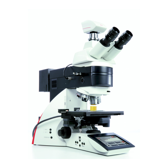
- Page 15 4. Overview of the Instrument Fig. 1 System overview DM6000 B with remote control element SmartMove and electronic box Leica CTR6000...
- Page 16 4. Overview of the Instrument Fig. 2 Left side of the stand Leica DM6000 B 8 Function keys field diaphragm Eyepiece 9 Transmitted light/incident light switch Eyepiece tube 10 Function keys aperture diaphragm Motorized tube MBDT 11 Function keys light intensity...
- Page 17 4. Overview of the Instrument 19 18 Fig. 3 Right side of the stand Leica DM6000 B Fig. 4 Remote control element SmartMove 15 Lamp housing for incident light Movement (x-direction) 16 Lamp housing for transmitted light Movement (y-direction) 17 Transmitted light filter, optional...
-
Page 18: Unpacking The Microscope
• Specimen stage with stage bracket • Power cable and PC connecting cable Note: • CD with Leica DMControl software package If at all possible, avoid touching the lens sur- faces of the objectives. If fingerprints do appear • Instructions and list of microscope default on the glass surfaces, remove them with a soft settings („Identification Sheet“) - Page 19 5. Unpacking the Microscope Installation location Transport Work with the microscope should be performed For shipping or transporting the microscope in a dust-free room, which is free of oil vapors and its accessory components, the original and other chemical vapors, as well as extreme packaging should be used.
-
Page 20: Assembling The Microscope
6. Assembly 6. Assembling the Microscope When using intermediate systems and optical The microscope components are logically as- accessories, the sequence may vary. sembled in this order: In this case, read Chapter "6.10 Optional accessories" → p. 34. • Stage •... -
Page 21: Stage
6. Assembly 6.1 Stage Note: Caution: For thicker specimens (Leica DM6000 M) the stage can be set to a correspondingly lower Before assembling the stage, make sure no ob- level. jectives are installed! • Place the specimen holder on the stage and Caution: fasten it with the two screws (5.1). -
Page 22: Condenser
6. Assembly 6.2 Condenser • Screw condenser head into Note: condenser. The condenser must be centered before using the microscope. • Using the condenser height adjuster (7.4), turn → Köhler illumination p. 46. the condenser holder (7.1) completely down- wards. Fig. -
Page 23: Tube And Eyepieces
Note: For eyepieces that are not included in shipment, we recommend to learn them in with the Soft- ware Leica DMControl, module: Configuration. Fig. 13 Motorized tube connection This ensures that the information about total Connector socket... -
Page 24: Objectives
(glare, UV-radiation, IR-radiation). Therefore, lamps have to be operated in Note: closed housings. We recommend to perform a parfocality adjust- ment with the Software Leica DMControl, module: Fine Tuning. Fig. 15 Lamp housing 107/2 Releasing the fastening screw Fig. 16 Fig. - Page 25 Be sure that the lamp is inserted straight. • Remove the lamp’s dust cover. Caution! Do not remove the lamp’s dust cover until Fig. 18 Rear side of Leica CTR6000 have installed lamp. Avoid Connection for lamp power cable from the stand fingerprints on the lamp.
-
Page 26: Light Sources For The Incident Light Axis
6. Assembly 6.6 Light Sources for the Incident Light Axis 106 z lamp housing This lamp housing is used with a 12V 100W halo- gen lamp or various gas discharge lamps. Caution! Light sources pose a potential irradiation Caution! risk (glare, UV-radiation, IR-radiation). - Page 27 • Connect the lamp housing to the power supply for incident light (symbol ) (22.4). Caution! • Now connect the lamp power cable of the microscope (22.5) to the Leica CTR6000 Do not remove the lamp’s dust cover until electronics box (18.1, p. 25) have installed lamp.
- Page 28 6. Assembly Inserting the gas discharge lamps (Hg and Xe) into the 106z lamp housing Hg and Xe lamps are powered by separate supply units. Read the separate instruction manual provided with these supply units. The following gas discharge lamps may be used and require different supply units and lamp mounts (Fig.
- Page 29 6. Assembly • To open the 106 z lamp housing, unscrew the fastening screws on the cover. Caution! • Remove the transport anchorage (red plastic Hg 50 burner: rod in place of the burner) in the lamp mount. After installation, the labeling must be upright. To do so, remove the lower clamp (23.1).
- Page 30 6. Assembly • Insert the lamp mount, with the burner in- stalled, into the lamp housing and tighten it with the screws (24.8). Fig. 24 106 z lamp housing (on the side, open) • Put the lid down again. Plug in the contact Cover raised plug as far as it goes and retighten the Collector...
-
Page 31: Equipping The Incident Light Turret Disc
6. Assembly Fig. 29 Removing the front cover 6.7 Equipping the Incident Light Turret Disc (4-fold filter turret) The receptacles on the turret are numbered. Filter receptacle According to your equipment, the individual Retention pin Front cover filter and/or reflector cubes have already pre- assigned positions. -
Page 32: Polarizer And Analyzer
• Remove the plug cap on the right side of the incident light axis (Fig. 34). Note: • Insert the polarizer into the receptacle until it At the Leica DM6000 M, 2 positions for bright latches in place. field and dark field reflector cubes may be set (depending on configuration). -
Page 33: Dic Prisms
Motorized polarizer 6.9 DIC Prisms • A motorized polarizer is already installed and With the microscope Leica DM6000 B the DIC ready for operation in the DIC condenser. objective prisms are already mounted in the DIC turret above the objective revolving nosepiece (Fig. -
Page 34: Optional Accessories
• Screw on the camera. service. Note: The use of a c-Mount or a Vario-Mount should be learned in with the Software Leica DMControl, module: Configuration. Connecting two cameras The dual port enables you to connect two cameras (one digital and one analog) to the microscope. - Page 35 6. Assembly Ergomodule Booster Lens/Excitation Manager For raising the eye level of the tube opening, the • Insert the filter slide into the front receptacle ergomodule may be used. on the right side of the stand (36.1, 37.1). It is fastened in place with the side clamping screw.
-
Page 36: Connecting The Leica Ctr6000 Electronics Box
• Connect the motorized stage to the socket Note: XY-Stage (38.2). We generally advise you not to use the Leica CTR6000 box with other microscopes. The serial • If the lamp power cable of the microscope no. of the matching stand can be found on the (39.3) has not been connected during... -
Page 37: Connecting The Computer
6. Assembly 6.12 Connecting the Computer 6.13 Connection to the Power Supply • After completing the assembly work, connect the Leica CTR6000 electronics box to the po- Note: wer supply using the power cable supplied (port 38.1). To start the Leica DMControl, the COM1 serial interface must not be occupied by another pro- •... -
Page 38: Startup
7. Startup 7. Startup 7.1 Functional Principle Based on an intelligent automation concept, the Leica DM6000 B/M can be operated via several control elements. 1. Intelligent automation • Switch between different contrasting methods by pressing just one button. Light rings, DIC-prisms, etc. - Page 39 7. Startup The table on the opposite page shows which microscope components can be operated with Note: (Reset-Function) which control elements. The microscope can be reset to the default settings: • When the microscope is switched off, press all 3 variable function keys on the left stand section.
- Page 40 7. Startup Function LeicaScreen Fixed Variable Turning Knobs Software Function Function SmartMove DMControl Keys at Keys at the the Stand Stand and at the SmartMove Change contrasting methods Toggle between TL and IL Select objectives learn in parfocality change operating mode (Dry/Imm) Illumination manager Magnification changer...
- Page 41 7. Startup Possible assignments for the variable Function Keys at the stand and at the SmartMove For Leica DM6000 B: Function key Meaning Bright field (transmitted light) Phase contrast (transmitted light) Interference contrast (transmitted light) Dark field (transmitted light) Polarization (transmitted light)
- Page 42 7. Startup For Leica DM6000 M: Function key Meaning Bright field (incident light) Interference contrast (incident light) Dark field (incident light) Polarization (incident light) CHANGE RL Switch through all incident light processes INT ↑ Increase brightness ( incident light) INT ↓...
-
Page 43: Switching On
LeicaScreen. See chapter ‘Trouble Shooting’, → p. 80. • Switch on the Leica CTR6000 Electronics Box at the on/off switch (41.1). When in operation, The microscopic components such as dia- the pilot lamp will light up green (41.2). All... -
Page 44: The Leicascreen
7. Startup 7.3 The LeicaScreen Navigation panel On the status page, the LeicaScreen shows the The navigation panel allows for quickly current microscope settings. The display selecting the navigation items: depends on the microscope’s configuration. Apart from this, the microscope can be operated via several menu levels on the LeicaScreen. -
Page 45: The Function Keys At The Stand
The last contrast The setting of the variable function keys can method used is restored. only be altered via the Software Leica The INT (43.3) keys adjust the light intensity indi- DMControl, module: Configuration. vidually. Settings can be made either in large or small increments. -
Page 46: The Remote Control Element Smartmove
‘Identification Sheet’. For the list of abbreviations see page → 41f. Note: The setting of the variable function keys can only be altered via the Software Leica DMControl, module: Configuration. 7.6 Köhler Illumination Fig. 45 Stage with specimen holder 7.6.1 Transmitted Light... - Page 47 7. Startup • Select objective with moderate • Using the condenser height adjuster (45.2), magnification (10x-20x). adjust the condenser until the edge of the field diaphragm appears in sharp relief. • If necessary, activate the transmitted light axis by pushing the TL/IL button (43.1). •...
-
Page 48: Incident Light
7. Startup 7.6.2 Incident Light • Focus on the specimen with the SmartMove or focus wheel. For each objective there are reasonable values assigned to aperture and field diaphragm. The • Adjust the light intensity with the INT keys incident light module is also pre-centered at the (43.3). -
Page 49: Checking Phase Contrast Rings
7. Startup Adjusting the aperture diaphragm 7.7 Checking Phase Contrast Rings (DM6000 M only) If your microscope is equipped for the use of phase contrast, the light rings that fit the objec- • Remove one eyepiece. tives are built into the condenser. The light rings are already centered in the •... - Page 50 7. Startup • Focus the ring structure (50a) by slightly loos- • Turn the centering screws until the dark ring ening the clamping ring (49.2) and moving the (phase ring in the objective) is congruent with eyelens (49.1). the slightly narrower bright ring (light ring in condenser) (50 c).
-
Page 51: Adjusting The Motorized Polarizer
• When a supply unit is used, it is turned on first. • Activate the incident light axis using the TL/IL function key. FLUO (Leica DM6000 B) or IL (Lei- ca DM6000 M) appears in the LeicaScreen. • Insert the reflector cube for lamp adjustment (Fig. - Page 52 7. Startup Caution! Never look directly into the beam path! When switching to the BF or Smith reflectors, there is a danger of being glared! Caution! Light sources pose a potential irradiation risk (glare, UV-radiation, IR-radiation). For the 106z lamp housing, the direct filament im- age (for halogen lamps) or direct arc image (for gas discharge lamps), and its mirror image are focused separately and adjusted to each other.
- Page 53 7. Startup Fig. 54 Direct lamp filament image focused, Centering the 12 V 100 W Halogen Lamp but not centered • In the adjustment window, you see the direct (in reality, the image is less focused) filament image and the mirror image, which in most cases are not aligned.
- Page 54 7. Startup Fig. 57 Direct arc image focused but decentered Centering the Hg 50 W mercury lamp (in reality, the image is less focused) • In the adjustment window, you see the direct arc image and the mirror image, which in most cases are not aligned.
- Page 55 7. Startup Fig. 60 Direct arc image focused but not centered Centering the Hg 100 W and Xe 75 W (in reality, the image is less focused) mercury lamps • In the adjustment window, you see the direct arc image and the mirror image, which in most cases are not aligned.
- Page 56 7. Startup Caution: In older lamps, the structure of the arc is no longer clearly recognizable. The image is then more like that of a HG 50 lamp. The im- age and mirror image can no longer be su- perimposed exactly. In this case, align both images.
-
Page 57: Operation
All motorized components will run through an external supply unit must be turned on initializing phase. separately (63.1). Switch on the Leica CTR6000 Electronics Box at Note: the on/off switch (64.1). When in operation, the pilot lamp will light up green (64.2). - Page 58 • When the microscope is switched off, Caution: press all 3 variable function keys on the left stand section. The focus position (DM6000 B only) and the lower threshold will also be stored when • Switch on the stand. switching off the microscope.
-
Page 59: Stages And Specimen Displacement
8.2 Stages and Specimen Displacement Store and recall stage positions Specimen Displacement with SmartMove With the Software Leica DMControl, module: DMOperation, different stage positions can be The stage can be moved with the turning knobs temporarily stored. Only the XY position is (66.1, 66.2) at the remote control element... -
Page 60: Focusing
We recommend to check parfocality before Setting thresholds via: setting the thresholds. If necessary, it can be learned in with the Software Leica DMControl, LeicaScreen - navigation item module: Fine Tuning. Software Leica DMControl, module: Fine Tuning Image Focus You can focus by using the turning knob (66.3) -
Page 61: Tubes
The values are pre-defined. The settings can be changed with the Software Note: Leica DMControl, module: Fine Tuning. Close any unused tube openings, as otherwise In the Coarse mode, the value is the same for all stray light can interfere with observation . - Page 62 The beam splitting between the observation and Variable function keys at the stand documentation outputs has a definite presetting (50:50). Software Leica DMControl - Modul: DMOperation BDT25+ tube: The beam splitting is set manually by pulling out HC L 2TU tube: a control bar.
-
Page 63: Eyepieces
Note: we recommend to learn them in with the Soft- The eyepiece’s aperture protector must be ware Leica DMControl, module: Configuration. removed or at least folded back, during This ensures that the information about total microscopy while wearing eyeglasses . - Page 64 It is possible to assign one objective to both operation modes, especially with dry objectives with >2mm working distance. The setting can be Caution! changed with Software Leica DMControl, module: Fine Tuning. Follow safety data sheet for immersion oil! Changing the operation mode •...
- Page 65 If one of the buttons for changing the operation When retrofitting objectives, they have to be mode (DRY or IMM) is pressed by mistake, the learned in with the Software Leica DMControl, previous mode can be reactivated by pressing module: configuration. Afterwards, parfocality the correct button.
-
Page 66: Magnification Changer
The selected factor is indicated in the accordingly. LeicaScreen or in the corresponding window of Coarse adjustment: 0-20 the Leica DMControl software and included in Fine adjustment: 0-255 the total magnification. • The light intensity is set and stored individually for each objective and each contrast method. -
Page 67: Aperture Diaphragm And Field Diaphragm
Variable function keys at the stand and at the SmartMove • The AP (73.2) keys for the aperture diaphragm and the FD keys (73.4) for the field diaphragm Software Leica DMControl, module: may be used to change each diaphragm’s set- DMOperation ting at any time. -
Page 68: Contrasting Methods For Leica Dm6000 B
9. Contrasting Methods for Leica DM6000 B 9. Contrasting Methods for Leica DM6000 B All contrasting methods can be selected and 9.1 Transmitted Light operated via the LeicaScreen, the variable 9.1.1 Bright Field (TL) function knobs and the Software Leica DMControl. -
Page 69: Phase Contrast
9. Contrasting Methods for Leica DM6000 B 9.1.2 Phase Contrast 9.1.3 Dark Field (TL) • Switch to the transmitted light axis (TL) by • Switch to the transmitted light axis (TL) by pushing the TL/IL button. pushing the TL/IL button. -
Page 70: Polarization
The display of the LeicaScreen, menu page automatically brought into the light path. ‘Status’ indicates POL. Combined procedure: Manual procedure: • For the Leica DM6000 B microscope, it is possible combine mechanical • Turn the polarizer on the underside of the motorized components. -
Page 71: Differential Interference Contrast
9. Contrasting Methods for Leica DM6000 B 9.1.5 Differential Interference Contrast (TL) Alternatively: • Manually rotate the polarizer on the under- • Switch to the transmitted light axis (TL) by side of the condenser into the light path (Fig. pushing the TL/IL button. -
Page 72: Fluorescence
9. Contrasting Methods for Leica DM6000 B 9.2 Fluorescence Selecting the fluorescence filter cube: • Switch to the fluorescent light axis (FLUO) by LeicaScreen - navigation item pushing the TL/IL button. Variable function keys at the stand and at • Insert a specimen and select an appropriate the SmartMove: Cube CW or Cube CCW objective. -
Page 73: Combi Mode
9. Contrasting Methods for Leica DM6000 B 9.3 Combi Mode Depending on the configuration of your Note: microscope, up to two combi modes are For FLUO/DIC the manual analyzer (81.1) has to possible: be used, as described in chapter 10.1.4, → p. -
Page 74: Contrasting Methods For Leica Dm6000 M
10. Contrasting Methods for Leica DM6000 M 10.Contrasting Methods for Leica DM6000 M All contrasting methods can be selected and 10.1.2 Dark Field (IL) operated via the LeicaScreen, the variable • Switch to the incident light axis (IL) by push- function knobs and the Software Leica ing the TL/IL button. - Page 75 10. Contrasting Methods for Leica DM6000 M • Switch to the incident light axis (IL) by push- • The ICR filter cube is automatically brought ing the TL/IL button. into the light path. • Select the POL (polarization) contrast method.
-
Page 76: Interference Contrast
10. Contrasting Methods for Leica DM6000 M 10.1.4 Interference Contrast (IL) 10.1.5 Fluorescence • Switch to the incident light axis (IL) by push- • Switch to the incident light axis (IL) with the ing the TL/IL button. function key TL/IL. -
Page 77: Transmitted Light
The analyzer cube is also automatically brought into the light path. 10.2.2 Polarization (TL) Combined procedure: • Switch to the transmitted light axis (TL) by • For the Leica DM6000 M microscope, it is pushing the TL/IL button. possible combine mechanical motorized components. -
Page 78: Trouble Shooting
11. Trouble Shooting 11. Trouble Shooting Problem Cause/Remedy Stand The microscope does not respond. Make sure that voltage is impressed. Make sure that the CTR6000 electronics box is connected to the power supply. Check the cable connections. Inform service technician to change the fuses. - Page 79 11. Trouble Shooting Cause/Remedy Problem Bright Field Use the correct immersion medium. The specimen can not be brought into focus. Lay the specimen with the cover glass to- wards the top. Make sure that the cover glass thickness is correct and that it suits the indication on the objective.
- Page 80 11. Trouble Shooting Problem Cause/Remedy Polarization No polarization contrast is possible. Bring the polarizer and analyzer into cross po- sition until they reach maximum darkness (without specimen) (→ p. 70, 75). Fluorescence The image is completely dark (no fluorescence). Open the shutter (→ p. 72). Select the incident light axis (IL) (→...
-
Page 81: Care Of The Microscope
12. Care of the Microscope 12.Care of the Microscope 12.2 Cleaning Caution! Unplug the power supply before performing Caution: cleaning and maintenance work! Residual fiber and dust can create unwanted Protect electrical components from background fluorescence. moisture! Cleaning Coated Parts Microscopes in warm and warm-damp climatic Dust and loose dirt particles can be removed zones require special care in order to prevent... -
Page 82: Handling Acids And Bases
Be absolutely certain to prevent the optics faces, the objectives must be sent to your and mechanical parts from coming into con- Leica subsidiary for repair. We also advise tact with these chemicals. against cleaning the inside surfaces of the eyepieces. -
Page 83: Essential Wear And Spare Parts
13. Essential Wear and Spare Parts 13. Essential Wear and Spare Parts Order No. Material No. Name Used for Replacement Lamp 11 500 974 Halogen lamp 12 V 100 W 107/2 lamp housing 11 500 137 High-pressure mercury burner 50 W 106 z lamp housing 11 500 138 High-pressure mercury burner 100 W... -
Page 84: Abbreviations And Pictograms
14. Abbreviations and Pictograms 14. Abbreviations and Pictograms Basic setting of microscope Contrasting method Magnification Documentation port Stage and focus settings LeicaScreen configuration Lower threshold not set Lower threshold set Focus position not set Focus position not set Transmitted light shutter open Transmitted light shutter closed Incident light shutter open Incident light shutter closed... - Page 85 14. Abbreviations and Pictograms Advanced Ergo Tube Aperture diaphragm Bright field COMBI Combination contrast method CUBE Filter cube Darkfield Differential interference contrast Field diaphragm FLUO Fluo axis (incident light) Interference contrast (reflected light) Interference contrast (transmitted light) Incident light (axis) Intensity MBDT Motorized Basic Documentation Tube...
-
Page 86: Index
Shutter 72 Connection to power supply 37 SmartMove 46, 59 Contrasting methods 12, 68, 74 Köhler illumination 22, 46 Software Leica DMControl 14, 18 Specimen displacement 59 Dark field 69, 74 Lamp housing 17 Specimen holder 21 Dark field stop 69... -
Page 87: Eu Declaration Of Conformity
EU directives. This declaration shall cease to be valid if modifications are made to the device without our approval. Product: DM6000 B Product: DM6000 M Model: Microscope...
Need help?
Do you have a question about the DM6000 B and is the answer not in the manual?
Questions and answers