Table of Contents
Advertisement
Advertisement
Chapters
Table of Contents

Subscribe to Our Youtube Channel
Related Manuals for Leica M220 F12


Summary of Contents for Leica M220 F12
- Page 1 Leica M220 F12 User Manual/Installation Manual 10 716 922 - Version 03...
- Page 2 The information provided by this manual is directly related to the operation of the equipment. Medical decision remains the responsibility of the clinician. Leica Microsystems has made every effort to provide a complete and clear user manual highlighting the key areas of product use. Should additional information regarding the use of the product be required, please contact your local Leica representative.
-
Page 3: Table Of Contents
Adjusting the parfocality 7.10 Changing accessories of the surgical microscope and balancing the swing arm 7.11 Attaching the sterile components 7.12 Starting up the surgical microscope 7.13 Checks before operation Leica M220 F12 / Ref. 10 716 922 / Version 03... -
Page 4: Introduction
Enter this data in your user manual and always refer to it when you contact us or the service workshop regarding any questions In this user manual the surgical microscope Leica M220 F12 is you may have. described. In the part "Installation manual" the assembly of the Leica M220 F12 is descriped. -
Page 5: Safety Notes
• The Leica M220 F12 surgical microscope is subject to special maintenance. Monitor compliance with this. Only use the Leica M220 F12 surgical microscope when it is free precautionary measures for electromagnetic compatibility. • Portable and mobile as well as stationary RF communications of defects. -
Page 6: Directions For The Operator Of The Instrument
Specific training is not required. All parts of the M220 shall not be serviced or maintained while • All parts of the Leica M220 F12 shall not be serviced or in use with a patient. maintained while in use with a patient. - Page 7 • The Leica Microsystems accessories described in this User Manual. • Other accessories, provided that these have been expressly approved by Leica as being technically safe in this context. Leica M220 F12 / Ref. 10 716 922 / Version 03...
-
Page 8: Dangers Of Use
Check that the optical components and accessories fit well and are fastened securely before the operation. Before changing equipment during an operation, swivel the microscope away from the operation area. Leica M220 F12 / Ref. 10 716 922 / Version 03... - Page 9 The LED module get very hot. Check that the LED module have cooled before you remove it. CAUTION Surgical microscope can tilting without warning. Always push the surgical microscope in park positon carefully. Leica M220 F12 / Ref. 10 716 922 / Version 03...
-
Page 10: Signs And Labels
Safety notes Signs and labels 4, 5, 6, 7,15 Leica M220 F12 / Ref. 10 716 922 / Version 03... - Page 11 MM = month (2 digits) g TT = day (2 digits) ANVISA Registration h Production starting date number (only brazil) Type label 15 UDI Label Follow the user manual Optical radiation Leica M220 F12 / Ref. 10 716 922 / Version 03...
-
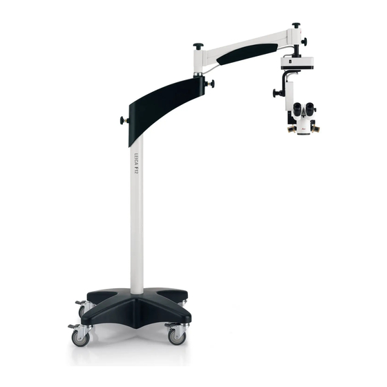
Page 12: Design
2 XY-unit (optional) 9 Horizontal arm 3 Focus unit 10 Column 4 Tilt head 11 Footswitch holder 5 Eyepieces 12 Base 6 Binocular tube 13 Footswitch 7 Optics carrier 14 Handle Leica M220 F12 / Ref. 10 716 922 / Version 03... -
Page 13: Functions
LED. It is in the optics carrier located. Balancing system With a balanced surgical microscope Leica M220 F12 you can move the optics carrier in any position without tilting or falling down. After balancing all movements during operation only need a minor force. -
Page 14: Controls
4 Cable holder for footswitch cable 5 Power cable strain relief device Tilt head/focusing unit Tilt head 1 Clamping lever for manual tilt movement Focusing unit 2 XY-unit reset button Leica M220 F12 / Ref. 10 716 922 / Version 03... -
Page 15: Footswitch (Standard Configuration)
Stand 1 Rotary knob for joint brake 2 Rotary knob for balancing 3 Brake knob for locking the vertical position 4 Footbrake engage/release lever Leica M220 F12 / Ref. 10 716 922 / Version 03... -
Page 16: Optics Carrier
Binocular tube, eyepiece, second observer tubes 1 Drive knob for interpupillary distance adjustment (optional) 2 Dioptric adjustment 3 Knurled ring for image correction Leica M220 F12 / Ref. 10 716 922 / Version 03... -
Page 17: Preparation Before Surgery
Push the surgical microscope to its installation location at the direction only using the horizontal arm. column (5). Move the surgical microscope into transport position and Lock the footbrakes at the installation location. tighten the articulation brakes. Leica M220 F12 / Ref. 10 716 922 / Version 03... -
Page 18: Positioning Surgical Microscope Over Operating Table
Connect the power cable (2) to the socket. Connect the footswitch in the socket (1) to the horizontal arm and guide it through the cable guide (3). Leica M220 F12 / Ref. 10 716 922 / Version 03... -
Page 19: Installing The Binocular Tube, Eyepiece And Objective
• Objective WD = 200 mm APO attachment (not a standard configuration) • Objective f = 175 mm • Objective f = 200 mm • Objective f = 225 mm Leica M220 F12 / Ref. 10 716 922 / Version 03... -
Page 20: Installing The Adapter For Accessories
Insert the adapter in the beam splitter. Tighten the rotary ring (1). Pull out the 2 empty filter holders (1). Fasten the filter in the filter holder. Reinsert the filter holder (1). Leica M220 F12 / Ref. 10 716 922 / Version 03... -
Page 21: Adjusting Second Observer Tube
Turn the attachment for second observer in the desired direction. Align the binocular tube horizontally. Adjust the diopter setting at the eyepiece. Correct the image with the knurled ring (2). Leica M220 F12 / Ref. 10 716 922 / Version 03... -
Page 22: Selecting Documentation Accessories
1/2 “ 2/3 “ 1 “ Photo/TV dual attachment Photo/TV dual attachment 250 mm 350 mm 35 mm 35 mm Digital Photo Digital Photo Camera Camera Field of view Monitor/image Leica M220 F12 / Ref. 10 716 922 / Version 03... -
Page 23: Adjusting The Eyebase And Eyepoint (Optional)
Observe the test object while zooming through the whole range. The image sharpness must remain constant at all magnifications. If it does not, then repeat points 2 to 4 of this procedure. Leica M220 F12 / Ref. 10 716 922 / Version 03... -
Page 24: Changing Accessories Of The Surgical Microscope And Balancing The Swing Arm
If more force is required to move it upwards: Turn the balancing knob (3) in the direction of the larger weight (counterclockwise). If more force is required to move it downwards: Leica M220 F12 / Ref. 10 716 922 / Version 03... -
Page 25: Checks Before Operation
See chapter 8.5. 7.13.3 Check the fastening of the power cable Check if the power cable is fasten to the swing arm using cable ties (see chapter 2.4.1 in the installation manual). Leica M220 F12 / Ref. 10 716 922 / Version 03... -
Page 26: Operation
Hold the microscope by the two handles (4) and position it. Adjusting the tilt Open the clamping lever (5). Adjust the tilt of the microscope. Close the clamping lever (5). Leica M220 F12 / Ref. 10 716 922 / Version 03... -
Page 27: Adjusting The Focus
On the lower potentiometer (3) of the board, set the speed to the desired value. Switching microscope illumination on and off Use button (1) to switch the microscope illumination on and off and to control the brightness. Leica M220 F12 / Ref. 10 716 922 / Version 03... -
Page 28: Adjusting The Working Distance
End the recording procedure on the camera (loss of data). Return the Leica M220 F12 surgical microscope to the transport position (see chapter 7.1). Switch off the Leica M220 F12 surgical microscope at the power switch (2, chapter 6.1). Leica M220 F12 / Ref. 10 716 922 / Version 03... -
Page 29: Components And Accessories
Check the total weight using the "Load table", chapter 9.3. Observer side Main surgeon Assistant 2 Assistant 1 Beam splitter Second observer stereo attachment Binocular tube Eyepiece Documentation port Leica M220 F12 / Ref. 10 716 922 / Version 03... - Page 30 Eyepiece, 10×, TC • Facilitates adjustments to the angle of toric Leica ToricEyePiece intraocular lenses via an integrated scale • For further information, see the separate operating and installation instructions Leica M220 F12 / Ref. 10 716 922 / Version 03...
-
Page 31: Video Accessories For Leica M220 F12
Set the maximum magnification (f = 100 mm) on the Leica Zoom Video Adapter. Focus the monitor image on the Leica Zoom Video Adapter. Set the desired magnification on the Leica Zoom Video Adapter. Leica M220 F12 / Ref. 10 716 922 / Version 03... -
Page 32: Load Table
Protective glass 0.06 kg Dust covers Documentation 10448215 Leica Zoom Video Adapter 0.76 kg 10448290 Leica Manual Video Adapter 0.42 kg 10448584 Leica HD C100 0.64 kg Complete Load System Leica M220 F12 / Ref. 10 716 922 / Version 03... -
Page 33: Care And Maintenance
• Store under UV light when not in use. • Use in continuously climate-controlled rooms only. • Keep them away from moisture and cover the instrument with a plastic cover filled with silica gel. Leica M220 F12 / Ref. 10 716 922 / Version 03... -
Page 34: Changing The Fuse
Check that the LED module have cooled before you remove it. The Leica M220 F12 does not have a built-in auxiliary lamp. A replacement LED module should always be kept at hand. If an LED burns out, another spare LED module should be purchased to be kept at hand by the user. -
Page 35: Diagnostics In Case Of Malfunctions
If the LED illuminates but the corresponding motor does not move, the motor may be defective. 1 LED footswitch button 2 Focus up/down 3 XY forwards/backwards 4 Magnification clockwise/counterclockwise 5 XY left/right Remove the focus cover (6, chapter 8.1). Leica M220 F12 / Ref. 10 716 922 / Version 03... -
Page 36: Notes On Reprocessing Of Resterilizable Products
Use some rinsing agent depending upon degree of contamination. Alcohol may also be used to clean the optics if heavy contamination such as fingerprints, grease streaks etc. is present. Leica M220 F12 / Ref. 10 716 922 / Version 03... - Page 37 1) This medical device falls within the validated stertility claims of the STERRAD®100S / STERRAD® 100NX / STERRAD®50 / STERRAD®200 Systems. Follow the instructions for use of your STERRAD® System User's Guide prior to sterilizing devices in STERRAD® Systems. Leica M220 F12 / Ref. 10 716 922 / Version 03...
-
Page 38: Disposal
Adjust the speed using the potentiometer on the footswitch (see chapter 8.1). XY movement is too slow. Speed set too low. Adjust the speed using the potentiometer on the footswitch (see chapter 8.1). Leica M220 F12 / Ref. 10 716 922 / Version 03... -
Page 39: Tv, Photography
Specimen is out of focus. The specimen is not precisely focused. Focus accurately, insert graticule if necessary. If your instrument has a malfunction that is not described here, please contact your Leica representative. Leica M220 F12 / Ref. 10 716 922 / Version 03... -
Page 40: Technical Data
UV filter UV and IR-free LED illumination Eye protection filter GG475 optional Protection filter 5× Light intensity Using a sterile drive knob on the optics adjustment carrier Leica M220 F12 / Ref. 10 716 922 / Version 03... -
Page 41: Optical Data
Field of view Ø (mm) min. max. min. max. 8.33× 15.1 76.6 12.1 10× 18.2 73.1 11.6 12.5× 22.7 59.2 13.5 Control unit Connection sockets for • Power cable • Footswitch Leica M220 F12 / Ref. 10 716 922 / Version 03... -
Page 42: Configurations And Weights
• Conducted disturbances, induced by RF fields IEC 61000-4-6: 10 V rms • Rated Power-frequency Magnetic Field IEC 61000- 4-8: 30 A/m • Voltage dips and interruptions IEC 61000-4-11: according to IEC 60601-1-2:2014 Leica M220 F12 / Ref. 10 716 922 / Version 03... -
Page 43: Standards Fulfilled
5 mm. • Further applied harmonized standards: IEC 62366, IEC60825-1, To move the Leica M220 F12 over thresholds of 20 mm, the wedge EN60825, IEC 62471, EN62471, EN 980. (1) included in the packaging can be used. -
Page 44: Dimensions
Technical data 13.11 Dimensions Unit of measure mm Leica M220 F12 / Ref. 10 716 922 / Version 03... - Page 45 Leica M220 F12 Installation Manual...
- Page 46 Mounting the optics carrier Installing the XY-unit (optional) and optics carrier Cabling Checklist Disassembly Instrument Setup Preparatory work Checking the functions Equipment Acceptance and Delivery to the Owner Delivery report Leica M220 F12 / Ref. 10 716 922 / Version 03...
-
Page 47: Preparations
Assembly material 4 Swing arm (horizontal and spring arm) Cable ties 5 Footswitch 6 Stand column Additionally, other miscellaneous accessories according to the specific order, e.g. tubes, objectives etc. Leica M220 F12 / Ref. 10 716 922 / Version 03... -
Page 48: Assembly
If no braking action is identified, contact Leica Microsystems Insert the column into the base Support. Fasten it using the 2 pretreated Allen screws (1) provided. Close off the threaded holes (1) using the plastic plugs provided. Leica M220 F12 / Ref. 10 716 922 / Version 03... -
Page 49: Mounting The Optics Carrier
Unscrew the 4 Phillips head screws (3) of the focus cover. Remove the focus cover. Loosely fasten the cable on the swing arm using the cable tie (5). Leica M220 F12 / Ref. 10 716 922 / Version 03... -
Page 50: Installing The Xy-Unit (Optional) And Optics Carrier
Fasten the XY-unit to the swing arm using the 4 pretreated Allen screws (10) provided. The red arrows on the XY-unit and the swing arm must be positioned one above the other. Leica M220 F12 / Ref. 10 716 922 / Version 03... -
Page 51: Cabling
Make sure to leave enough cable length at the articulation points so as not to restrict freedom of movement. Route the video cable alongside the existing electronics cable and fasten it using cable ties. Leica M220 F12 / Ref. 10 716 922 / Version 03... -
Page 52: Checklist
Checklist Checklist Disassembly Are all the cables routed correctly and not pinched? Disassemble the Leica M220 F12 surgical microscope in the opposite order in which it was assembled. Leica M220 F12 / Ref. 10 716 922 / Version 03... -
Page 53: Instrument Setup
Checking the functions Check the following functions in accordance with the user manual: Release all brakes of the Leica M220 F12 and move the stand over the entire range of movement. Result: The brakes disengage; the microscope can be moved over the entire range of movement freely and without noise. -
Page 54: Equipment Acceptance And Delivery To The Owner
The system as a whole should not be started up until acceptance by Leica Microsystems Service has taken place. This is followed by the training of the personnel. Leica M220 F12 / Ref. 10 716 922 / Version 03... -
Page 55: Delivery Report
Signature Location Date This acceptance certificate must be filled out by the responsible installation engineer and a copy given to both the customer and the Leica Microsystems representative. Must be retained for: 20 years Leica M220 F12 / Ref. 10 716 922 / Version 03... - Page 56 10 716 922en/03 Copyright © by Leica Microsystems GmbH, 2021, Switzerland. Subject to modifications. Printed – 01.2021 LEICA and the Leica Logo are registered trademarks of CONNECT Leica Microsystems IR GmbH. WITH US! Leica Microsystems (Schweiz) AG · Max Schmidheiny Strasse 201 · CH-9435 Heerbrugg T +41 71 726 3333 ·...
Need help?
Do you have a question about the M220 F12 and is the answer not in the manual?
Questions and answers