
Subscribe to Our Youtube Channel
Related Manuals for FiberHome AN6000-7


Summary of Contents for FiberHome AN6000-7
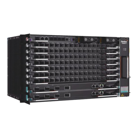
- Page 1 AN6000-7 Optical Line Terminal Equipment Quick Installation Guide Version: A Code:MN000004297 FiberHome Telecommunication Technologies Co., Ltd.
- Page 2 Please contact your local sales representative, service representative or distributor for any help needed at the contact information shown below. Fiberhome Telecommunication Technologies Co., Ltd. Address: No. 67, Guanggu Chuangye Jie, Contact us...
-
Page 3: Installation Procedure
Installation Procedure Operation procedure Start Reference information Safety precautions Installation preparations Installation tools Installing cabinets Subrack overview Requirements and Installing subracks Equipment layout precautions for operating cards Installing and securing subracks Operation rules for plugging / unplugging optical modules Installing cards and components Preparation for cable Installing cards... -
Page 4: Safety Precautions
Safety Precautions Warning Laser Safety To prevent laser radiation from injuring eyes, do not look into the Laser class end face of a fiber or fiber connector directly with naked eyes. identifier Caution ESD Protection Carpets or other materials that easily generate static electricity should not be used on the floor of the equipment room. -
Page 5: Installation Tools
Installation Tools Electric drill Ladder Vacuum cleaner Marker pen (including the drill bits) Claw hammer (insulated) Long tape Knife Spirit level Cross screwdriver (insulated) Flat screwdriver (insulated) Crimping pliers Hydraulic pliers Wire clipper Sharp nose pliers Diagonal pliers Wire stripper Torque wrench Insulating Combination wrench... -
Page 6: Installing Cabinets
Subrack with mounting ears for a 21-inch 266 mm × 530 mm × 253.8 mm (excluding the fiber cabinet passage unit) Note 1: The AN6000-7 subrack is equipped with the mounting ears for a 19-inch cabinet by default. -
Page 7: Equipment Layout
Equipment Layout Rules for Arranging Subracks When multiple AN6000-7 subracks are to be installed in a cabinet, usually arrange the subracks from the top down. A cabinet can house three AN6000-7 subracks at most. Subracks are mounted on the front vertical mounting flanges of a 19-inch or 21-inch cabinet. - Page 8 Installing Subracks in a 19-inch Cabinet Flat Cross Marker pen screwdriver screwdriver Installing Components Screw Panel screw Fiber passage unit Slide Rails for a 19-inch Cabinet Procedure Mark the positions for mounting the Install the fiber passage unit. Install the slide rails. subrack and slide rails on the vertical mounting flanges of the cabinet.
- Page 9 Installing Subracks in a 21-inch Cabinet Installing Components Flat Cross Marker pen screwdriver screwdriver Screw Panel screw Slide Rails for a 21-inch Cabinet Fiber passage unit Adapter Mounting Ears Procedure Mark the positions for mounting the Install the fiber passage unit. Install the slide rails.
- Page 10 Requirements and Precautions for Operating Cards Caution Do not contact cards with bare hands. Always wear ESD protection gloves or an ESD protection wrist strap when operating cards. When holding a card, put your hands on its panel, and do not touch any components or wires on the card, or metal conductors in the socket.
- Page 11 Operation Rules for Plugging / Unplugging Optical Modules Plugging an Optical Module Hold an optical module, and plug it into a card along the desired EMI cage. Material Order number number Working wavelength Transmission distance Rate Material code of module part Unplugging an Optical Module Grab the handle of an optical module with the Fiber puller...
- Page 12 Installing Cards and Components Installing Cards Caution ESD protection gloves / Before installing a card, check the pins and card connector on the wrist strap backplane. Follow the rules for installing cards. If you feel a resistance when inserting a card, pull it out and make sure that you are inserting a card of the correct type to a correct slot in a correct Cross Captive...
- Page 13 (This guide uses the top access wiring mode as an example). The AN6000-7 uses the PDP850A (3000064). Instruction Before laying out wires and cables, you need to remove the front panel of the PDP. If space is limited for operations, remove the baffle at the bottom of the PDP as well.
- Page 14 Cabinet with Routed Fibers and Cables A Subrack for PON Services...
- Page 15 Connecting Power Cables and Protection Earth Ground Cables 11.1 Connecting the Subrack Protection Earth Ground Cable Flat Cross Marker pen Panel screw screwdriver screwdriver Subrack protection earth ground cable Subrack protection earth ground cable Floating nut Earth ground point on the vertical mounting flange Subrack protection...
- Page 16 Instruction The protection earth ground cable for a PDP has been connected with the PE terminal before delivery of the PDP; you only need to connect the other end of the cable to the earth ground point on the top of a cabinet on site. Connect the cabinet earth ground cable to the earth ground bar in the equipment room.
- Page 17 11.3 Connecting Subrack DC Power Cables Caution Make sure that the power control switch for the corresponding subrack on the PDP is placed in the OFF position before laying the power cables. Completely insert the cord end terminals into the terminal blocks on the PDP. To ensure good connection, the metal part exposed should not exceed one sixth of the overall metal length.
-
Page 18: Connecting Network Cables
Connecting Network Cables Connected to the Opposite End Equipment Network cable Instruction The network cable is routed in the space between the subrack side panel and the cabinet side panel behind the left front vertical mounting flanges as follows: Led to the top and then front side of the subrack, threaded through the wiring holes of the fiber passage unit, and then connected to the CIOA card. - Page 19 Rules for Binding Cables Rules Illustration Keep the bound cables neat. The horizontal cables should be bound with even distance between cable ties. Do not join several cable ties to make a longer one and bind cables with it; otherwise, the tensity may be reduced.
- Page 20 Instruction Select the right types of optical fiber jumpers according to the types of optical interfaces on the local and opposite end equipment. The optical interfaces on the AN6000-7 match two types of optical fiber connectors: LC/PC and SC/PC. LC/PC Optical Fiber Connector...
- Page 21 13.2 Connecting Internal Optical Fibers Connected to the ODF Optical fiber (LC) Optical fiber (SC) Instruction Route the fiber jumpers along the front vertical mounting flange on the left side of the cabinet, thread them through the wiring holes of the fiber passage unit, and then connect them to the desired cards.
- Page 22 13.3 Arrangement After Layout After the connection of optical fibers is completed, installers should bind the optical fibers between the cabinet entrance and the fiber passage area with dedicated fiber binding straps to secure them. Connect the optical fibers on the ODF side. Information of the local Remove the temporary labels;...
-
Page 23: Post Installation Inspection
Checking Before Power-on Caution The AN6000-7 uses -48 V DC power supply with an acceptable voltage range from -40 V to -57 V. Before powering on the equipment, installers should: 1. Confirm that the cabinet power cables are correctly connected with the external power supply equipment. -
Page 24: Do's And Don'ts
Dos and Don’ts Direct or indirect contact Promptly report any (through damp objects) with Do not install / operate the Do not connect or remove conditions that may lead to high voltage power supply equipment or lay cables power cables while they security problems.
Need help?
Do you have a question about the AN6000-7 and is the answer not in the manual?
Questions and answers