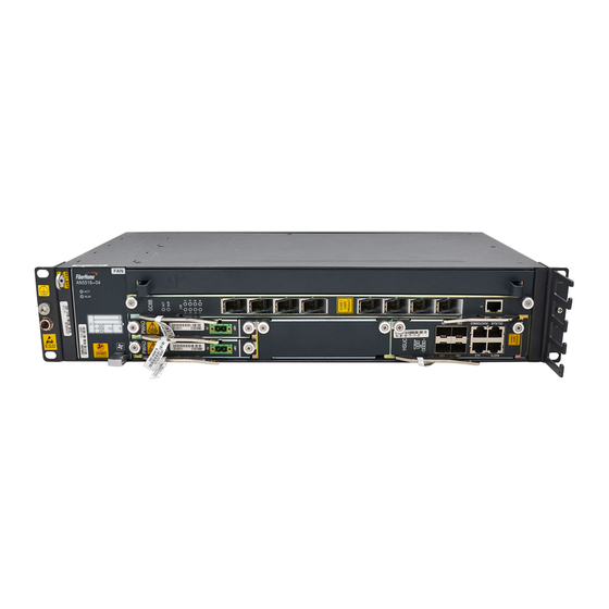
FiberHome AN5116-06B Hardware Description

FiberHome AN5116-06B Hardware Description

Optical line terminal equipment
Hide thumbs Also See for AN5116-06B:
Table of Contents

Advertisement

MN000003085

Advertisement

Table of Contents
loading
Need help?

Need help?

Do you have a question about the AN5116-06B and is the answer not in the manual?

Questions and answers

Subscribe to Our Youtube Channel

Summary of Contents for FiberHome AN5116-06B

  • Page 1 MN000003085...
  • Page 5 AN5116-06B/AN5516-06/ AN5516-04 Optical Line Terminal Equipment Hardware Description Version: C Code: MN000003085 FiberHome Telecommunication Technologies Co., Ltd. November 2017...
  • Page 7 Please contact your local sales representative, service representative or distributor for any help needed at the contact information shown below. Fiberhome Telecommunication Technologies Co., Ltd. Address: No. 67, Guanggu Chuangye Jie, Wuhan, Hubei, China Zip code: 430073...
  • Page 9 Legal Notice are trademarks of FiberHome Telecommunication Technologies Co., Ltd. (Hereinafter referred to as FiberHome) All brand names and product names used in this document are used for identification purposes only and are trademarks or registered trademarks of their respective holders.
  • Page 11: Table Of Contents

    Contents Documentation Guide ..................1 Subrack......................3 Subrack Models and Specifications...........4 Introduction to the AN5116-06B Subrack ...........4 2.2.1 Structure and Dimensions ...........5 2.2.2 Slot Distribution and Matching Cards........7 2.2.3 Anti-dust Screen ..............8 2.2.4 Fan Unit................10 2.2.5 Ventilation Principle ............12 Introduction to the AN5516-06 Subrack ...........13 2.3.1...
  • Page 12 3.4.1 Function Overview of the Switch Uplink Card.....38 3.4.2 HSUB ................39 3.4.3 HSUC................43 Uplink Card..................45 3.5.1 Function Overview of the Uplink Card........46 3.5.2 HU1A ................46 3.5.3 HU1B ................49 3.5.4 HU2A ................51 3.5.5 HU2C ................53 3.5.6 HU4A ................56 3.5.7 GU6B ................57 3.5.8 GU6F ................59 Power Card ..................61...
  • Page 13 3.9.3 APSA ................97 3.9.4 VPSA ................100 3.9.5 FTSA................102 3.9.6 CATA................105 3.9.7 CVTA................108 3.9.8 SHUA ................111 3.9.9 BROA................113 3.9.10 SETA................115 3.10 Vector Card .................. 118 3.10.1 VCNA ................118 3.10.2 FCEA ................120 3.11 Ethernet Service Card..............121 3.11.1 GSOF................121 3.12 TDM Service Card ................124 3.12.1 CE1B ................124...
  • Page 14 TDM Optical Module ..............151 Wire and Cable ...................152 Cable Overview ................153 Power Cable.................154 5.2.1 Cabinet Power Cable ............154 5.2.2 Subrack Power Cable (AN5116-06B) ......157 5.2.3 Subrack Power Cable (AN5516-06).........159 5.2.4 Subrack DC Power Cable (AN5516-04)......160 5.2.5 Subrack AC Power Cable (AN5516-04)......162 Protection Earth Ground Cable .............163...
  • Page 15 6.3.3 Layout of the AN5516-04 Subrack........199 PDP ......................204 Overview of PDPs.................205 PDP Selection Principle ..............205 Panel and Terminal ...............206 7.3.1 PDP850A (3000064)............207 7.3.2 PDP296B (3000068)............210...
  • Page 17: Documentation Guide

    Document Orientation Hardware Description gives a detailed introduction to the hardware components of the OLT equipment AN5116-06B/AN5516-06/AN5516-04. This manual is designed for readers who want to have a detailed knowledge about the hardware of the equipment and who need the hardware information to guide their operation and maintenance of the equipment.
  • Page 18 AN5116-06B/AN5516-06/AN5516-04 Optical Line Terminal Equipment Hardware Description Chapter Content Module types, parameters, and mappings between modules Optical Module and cards Functions, models, structures, connections and parameters of Wire and Cable wires and cables Types, appearance and dimensions of cabinets; equipment...
  • Page 19: Subrack

    Subrack The OLT series equipment offered by FiberHome mainly includes the AN5116-06B/ AN5516-06/AN5516-04. Subrack Models and Specifications Introduction to the AN5116-06B Subrack Introduction to the AN5516-06 Subrack Introduction to the AN5516-04 Subrack Version: C...
  • Page 20: Subrack Models And Specifications

    Short term: -5℃ to 55℃ Storage temperature -40℃ to 70℃ Relative humidity for 10% to 100% storage Introduction to the AN5116-06B Subrack This section introduces the structure, dimensions, slot distribution, anti-dust screen, fan unit and ventilation principle of the AN5116-06B subrack. Version: C...
  • Page 21: Structure And Dimensions

    2 Subrack 2.2.1 Structure and Dimensions Subrack Structure Name Function ① Facilitates air cooling for the equipment. Fan unit Connects with card modules, serves as the bus, and ② Backplane provides functional interfaces and power interfaces. Subrack earth ground ③ Connects with the subrack earth ground cable.
  • Page 22 Connects with the PDP through the subrack power cable of the ① PWR-A/PWR-B Power interface AN5116-06B to provide DC power supply for the subrack. Provides information such as the MAC address, equipment model, subrack version number, and backplane card number for Electrical ②...
  • Page 23: Slot Distribution And Matching Cards

    2 Subrack 2.2.2 Slot Distribution and Matching Cards The AN5116-06B subrack provides 20 vertical slots in total. The slots can be classified as follows according to the types of cards that they house: Classifica- Card Type Slot Card Name tion...
  • Page 24: Anti-Dust Screen

    If you want to use the vector card and the service card supporting the SLV function on the AN5116-06B, please abide by the following rules for slot distribution. The vector card can only be applied to slot 8 or 11, adjacent to the slot for the core switch card.
  • Page 25 2 Subrack Function The self-latching anti-dust screen of the AN5116-06B is located at the bottom of the subrack. It is used together with the shield plate at the air inlet to prevent dust from entering the subrack. Structure Figure 2-2 shows the appearance and components of the anti-dust screen.
  • Page 26: Fan Unit

    AN5116-06B/AN5516-06/AN5516-04 Optical Line Terminal Equipment Hardware Description Figure 2-3 Shield Plate Components (Top View) 2.2.4 Fan Unit Model The model number of the fan unit for the AN5116-06B is 405000150. Appearance Version: C...
  • Page 27 2 Subrack Working Principle u Located on the top of the subrack, the fan unit exhausts hot air for heat dissipation. A flow of cooling air is forced into the subrack through the bottom of the subrack. After passing through each working card in the subrack, the air is exhausted from the top of the subrack.
  • Page 28: Ventilation Principle

    Ventilation Principle Ventilation Process A flow of cooling air is forced into the AN5116-06B subrack through the bottom of the subrack. Drawn by the fan unit located at the top of the subrack, the cool air goes upward and passes through the subrack, and is then exhausted from the top of the subrack.
  • Page 29: Introduction To The An5516-06 Subrack

    2 Subrack Introduction to the AN5516-06 Subrack This section introduces the structure, dimensions, slot distribution, anti-dust screen, fan unit and ventilation principle of the AN5516-06 subrack. 2.3.1 Structure and Dimensions Subrack Structure S.N. Name Function ESD protection earth ① Connects to the ESD protection unit. ground fastener ②...
  • Page 30: Slot Distribution And Matching Cards

    AN5116-06B/AN5516-06/AN5516-04 Optical Line Terminal Equipment Hardware Description Note: The height in the table excludes the fiber passage unit. The mounting ears of the AN5516-06 subrack for mounting in a 19-inch cabinet are connected with the left and right panels of the subrack respectively.
  • Page 31 2 Subrack Card Type Classification Slot Card Name OTDR Line Diagnosis and ODMA / ODMB / ODMC Measurement Card Clock card (see TIMA) TIMA Slots for core 9 to 10 Core Switch Card HSWA / HSWB / HSWD switch cards Power card (see Power Slots for power...
  • Page 32: Anti-Dust Screen

    AN5116-06B/AN5516-06/AN5516-04 Optical Line Terminal Equipment Hardware Description Figure 2-4 Slot Distribution Rules for the Cards Supporting the SLV Function 2.3.3 Anti-dust Screen Model The model number of the anti-dust screen for the AN5516-06 subrack is 405000029. Function The anti-dust screen is located on the left side of the fan unit in the AN5516-06 subrack.
  • Page 33: Fan Unit

    2 Subrack 2.3.4 Fan Unit Model The model number of the fan unit for the AN5516-06 is 405000248. Appearance Working principle u Located on the left part of the subrack, the fan unit is used for air cooling by blowing air. The cool air enters the subrack from the left side of it, passes through each working card in the subrack, and is then exhausted from the right side of the subrack.
  • Page 34: Ventilation Principle

    AN5116-06B/AN5516-06/AN5516-04 Optical Line Terminal Equipment Hardware Description In the manual mode, the fan unit operates at the speed set in the network management system. In the intelligent mode, the core switch card of the equipment automatically selects a speed for the fan unit according to the card temperature detected, and the fan unit will operate at the selected speed.
  • Page 35: Introduction To The An5516-04 Subrack

    2 Subrack Ventilation Principle Introduction to the AN5516-04 Subrack This section introduces the structure, dimensions, slot distribution, fan unit and ventilation principle of the AN5516-04 subrack. 2.4.1 Structure and Dimensions Subrack Structure Name Function ① Mounting ear Secures the subrack in the cabinet. ESD protection earth ②...
  • Page 36: Slot Distribution And Matching Cards

    AN5116-06B/AN5516-06/AN5516-04 Optical Line Terminal Equipment Hardware Description Name Function Subrack earth ground ③ Connects with the subrack earth ground cable. point ④ Fiber passage unit Facilitates routing and arranging of fibers and cables. ⑤ Facilitates air cooling for the equipment.
  • Page 37: Fan Unit

    2 Subrack Card Type Classification Slot Card Name EPON / 10G EPON Service Card EC4B / EC8B / ECOB / XG8A GPON / XG-PON / GPON&XG-PON GC4B / GC8B / GCOB / XP4A / XP8A Combo Service Card PPDA / PPEA / APSA / VPSA / FTSA / MSAN Service Card CATA / CVTA / SHUA Slots for service...
  • Page 38 AN5116-06B/AN5516-06/AN5516-04 Optical Line Terminal Equipment Hardware Description Working principle u Located on the left part of the subrack, the fan unit is used for air cooling by blowing air. The cool air enters the subrack from the left side of it, passes through each working card in the subrack, and is then exhausted from the right side of the subrack.
  • Page 39: Ventilation Principle

    2 Subrack Item Specification Typical power consumption (the power ≤ 12W consumption when the fan unit is operating at speed level 3) Maximum power consumption (the power ≤ 32W consumption when the fan unit is operating at speed level 0) 2.4.4 Ventilation Principle Ventilation Process...
  • Page 40: Card

    Card Card Structure and Dimensions Overview of Cards Core Switch Card Switch Uplink Card Uplink Card Power Card EPON / 10G EPON Service Card GPON / XG-PON / GPON&XG-PON Combo Service Card MSAN Service Card Vector Card Ethernet Service Card TDM Service Card OTDR Line Diagnosis and Measurement Card Other Cards...
  • Page 41: Card Structure And Dimensions

    3 Card Card Structure and Dimensions Card Structure The following introduces the card structure, using the XP8A service card applicable to all the three OLT subrack models as an example. Figure 3-1 Card Structure Name Function ① Card name Identifies the name of the card. Contains various indicator LEDs, such as the interface ②...
  • Page 42 AN5116-06B/AN5516-06/AN5516-04 Optical Line Terminal Equipment Hardware Description Name Function Provides card-related identifiers; protects and secures the ③ Card panel card. Provides interfaces for connection with different devices to ④ Interface implement the card functions. Facilitates plugging or removing a card, protects the card ⑤...
  • Page 43: Overview Of Cards

    116 mm × 18.6 mm × 224.2 mm Common interface card (CIO) 138 mm × 34.7 mm × 224.5 mm Fan card (FAN) (AN5116-06B) 437 mm × 46.5 mm × 246 mm Fan card (FAN) (AN5516-06) 244.3 mm × 58.3 mm × 224.3 mm Fan card (FAN) (AN5516-04) 85.4 mm ×...
  • Page 44 AN5116-06B/AN5516-06/AN5516-04 Optical Line Terminal Equipment Hardware Description Matching Subracks Power Card Type Consump- Card Name Card Number AN5116-06B AN5516-06 AN5516-04 tion ≤ 33 W √ × × 2201894 ≤ 30 W √ × × Power card PWRA 2201471 ≤ 8 W √...
  • Page 45: Core Switch Card

    The core switch cards aggregate, switch and control traffic flow, process Layer-2 protocols, and manage the faults, performance and configuration of the equipment. They are used on the AN5116-06B and the AN5516-06. 3.3.1 Function Overview of the Core Switch Card...
  • Page 46 AN5116-06B/AN5516-06/AN5516-04 Optical Line Terminal Equipment Hardware Description Classification Function Supports NGN voice service and voice protocols SIP and H.248. Voice functions Supports port-based and IEEE 802.1q-based VLAN. VLAN functions Supports selective QinQ VLAN and VLAN translation. Layer 2 switching Supports Layer 2 switching.
  • Page 47: Hswa

    3 Card u The HSWD (2202258) card supports the 1588 / synchronous Ethernet clock function. The core switch cards provide interfaces as follows: Local Commissioning Out-of-band Management Card Name USB Interface Serial Port Network Port HSWA HSWB HSWD 3.3.2 HSWA Basic Information Overview of Cards shows the number, matching subracks and power consumption...
  • Page 48 AN5116-06B/AN5516-06/AN5516-04 Optical Line Terminal Equipment Hardware Description Table 3-2 Indicator LEDs (Continued) Meaning Description Identifier Color Status Active / The card is active. standby status Green The card is standby. indicator LED Note 1: When the ACT indicator LED of a standby card is blinking or extinguished, do not unplug the active card or execute the active-to-standby switching command , which may cause loss of card configuration data.
  • Page 49: Hswb

    3 Card Working Principle Figure 3-3 Working Principle of the HSWA Card u The control module is used for configuring the entire system, collecting and reporting statuses, processing protocols, and providing the local commissioning serial port and the out-of-band management network interface. u The switch module is used to switch service data.
  • Page 50 AN5116-06B/AN5516-06/AN5516-04 Optical Line Terminal Equipment Hardware Description Table 3-4 Indicator LEDs Meaning Description Identifier Color Status The card is working normally. Blinking slowly The card is being initialized. Working Note 1 Green The card is standby and is receiving a...
  • Page 51: Hswd

    3 Card Function Function Overview of the Core Switch Card. Working Principle Figure 3-4 Working Principle of the HSWB Card u The control module is used for configuring the entire system, collecting and reporting statuses, processing protocols, and providing the local commissioning serial port and the out-of-band management network interface.
  • Page 52 AN5116-06B/AN5516-06/AN5516-04 Optical Line Terminal Equipment Hardware Description Table 3-5 Interfaces Meaning Description Identifier Connects with the USB storage device. USB interface Local commissioning Connects to a CLI network management CONSOLE serial port computer. Out-of-band Connects to an out-of-band network management network management computer.
  • Page 53 3 Card Interface Specifications Specification Item Interface type RJ-45 CONSOLE Asynchronous EIA / TIA-232 Interface standard interface Baud rate 9600 Bd Function Function Overview of the Core Switch Card. Working Principle Figure 3-5 Working Principle of the HSWD Card (2201069) Figure 3-6 Working Principle of the HSWD Card Supporting the 1588 Function (2202258) u The control module is used for configuring the entire system, collecting and...
  • Page 54: Switch Uplink Card

    AN5116-06B/AN5516-06/AN5516-04 Optical Line Terminal Equipment Hardware Description Switch Uplink Card The switch uplink cards aggregate, switch, control and uplink traffic flow, process Layer-2 protocols, and manage the faults, performance and configuration of the equipment. They are used on the AN5516-04.
  • Page 55: Hsub

    3 Card Classification Function Supports multiple management VLANs and multiple management IP addresses. Supports reporting the environment monitoring information and the alarm information for the equipment and the connected ONUs. Supports PON port protection. Supports uplink port trunking and port dual-uplink protection. Reliability functions Supports RSTP to avoid generation of loops in the network.
  • Page 56 AN5116-06B/AN5516-06/AN5516-04 Optical Line Terminal Equipment Hardware Description Table 3-7 Interfaces Meaning Description Identifier 10GE uplink optical 10GE1 (1), 10GE2 (2) Connect to the IP network. interface Connect to the IP network. Support both GE optical modules and GE GE uplink optical / electrical modules.
  • Page 57 3 Card Table 3-8 Indicator LEDs (Continued) Meaning Description Identifier Color Status Uplink port The port is connected. connection Blinking The port is receiving / transmitting data normally. LNK 1 to 4 status Green indicator The port is not connected. Technical Specifications Specification Item...
  • Page 58 AN5116-06B/AN5516-06/AN5516-04 Optical Line Terminal Equipment Hardware Description Specification Item 1.25G-100m-TDM-SFP (10/100/1000BASE- GE electrical module 1.25G-100m-TDM-SFP (1000BASE-T) 1.25G-0.55km-TDM-SFP (1000BASE-SX) 1.25G-15km-TDM-SFP (1000BASE-LX) Matching GE optical module Note 1 1.25G-40km-TDM-SFP (1000BASE-EX) module 1.25G-80km-TDM-SFP (1000BASE-ZX1) 10G-10km-TDM-SFP+ (I-64.1) 10GE optical module 10G-40km-TDM-SFP+ (10GBASE-ER/EW) 10G-80km-TDM-SFP+ (L-64.2)
  • Page 59: Hsuc

    3 Card u The power module supplies power to each functional module of the card. u The clock module provides clock signals for each functional module of the card. 3.4.3 HSUC Basic Information Overview of Cards shows the number, matching subracks and power consumption of the card.
  • Page 60 AN5116-06B/AN5516-06/AN5516-04 Optical Line Terminal Equipment Hardware Description Table 3-10 Indicator LEDs (Continued) Meaning Description Identifier Color Status Blinking The card is receiving a configuration command. quickly The card is not powered on. Active / standby The card is active. status indicator Green The card is on standby or faulty.
  • Page 61: Uplink Card

    3 Card Specification Item 1.25G-40km-TDM-SFP (1000BASE-EX) 1.25G-80km-TDM-SFP (1000BASE-ZX1) Note 1: See GE / 10GE Module for the specifications of the modules. Function Function Overview of the Switch Uplink Card. Working Principle Figure 3-8 Working Principle of the HSUC Card u The uplink module provides four uplink interfaces to connect the service flows of the entire system to the IP network.
  • Page 62: Function Overview Of The Uplink Card

    AN5116-06B/AN5516-06/AN5516-04 Optical Line Terminal Equipment Hardware Description 3.5.1 Function Overview of the Uplink Card The uplink card supports the following functions: u Provides the uplink ports. u Each uplink port can be used as the network management port to connect with a network management computer.
  • Page 63 3 Card Table 3-11 Interfaces Meaning Description Identifier 10GE uplink optical XFP1 Connects to the IP network. interface Connect to the IP network. Support both GE optical modules and GE GE uplink optical / electrical modules. The electrical modules SFP2 to 5 electrical interface include the 10 / 100 / 1000M self-adaptive electrical module and the 1000M electrical...
  • Page 64 AN5116-06B/AN5516-06/AN5516-04 Optical Line Terminal Equipment Hardware Description Matching Module Specification Item 1.25G-100m-TDM-SFP (10/100/1000BASE-T) GE electrical module 1.25G-100m-TDM-SFP (1000BASE-T) 1.25G-0.55km-TDM-SFP (1000BASE-SX) 1.25G-15km-TDM-SFP (1000BASE-LX) GE optical module 1.25G-40km-TDM-SFP (1000BASE-EX) 1.25G-80km-TDM-SFP (1000BASE-ZX1) 10G-10km-TDM-XFP (I-64.1) 10GE optical module 10G-40km-TDM-XFP (S-64.2b) 10G-80km-TDM-XFP (L-64.2) Note 1: See GE / 10GE Module for the specifications of the modules.
  • Page 65: Hu1B

    3 Card 3.5.3 HU1B Basic Information Overview of Cards shows the number, matching subracks and power consumption of the card. Panel Description Table 3-13 Interfaces Meaning Description Identifier 10GE uplink optical SFP+1 Connects to the IP network. interface Connect to the IP network. Support both GE optical module and GE GE uplink optical / SFP2 to 5...
  • Page 66 AN5116-06B/AN5516-06/AN5516-04 Optical Line Terminal Equipment Hardware Description Technical Specifications Item Specification IEEE 802.3, IEEE 802.3z, IEEE 802.3ae, etc. Network standards Operating modes 10 / 100 / 1000 Mbit/s, 10 Gbit/s Matching Module Specification Item 1.25G-100m-TDM-SFP (10/100/1000BASE-T) GE electrical module 1.25G-0.55km-TDM-SFP (1000BASE-SX) 1.25G-15km-TDM-SFP (1000BASE-LX)
  • Page 67: Hu2A

    3 Card u The control module loads the card software, controls the card operation, and manages the card. u The power module supplies power to each functional module of the card. u The clock module provides clock signals for each functional module of the card. 3.5.4 HU2A Basic Information...
  • Page 68 AN5116-06B/AN5516-06/AN5516-04 Optical Line Terminal Equipment Hardware Description Table 3-16 Indicator LEDs (Continued) Meaning Description Identifier Color Status The port is connected with the upper-layer device. Port status The port is transmitting data to or receiving data LNK1 to Blinking quickly...
  • Page 69: Hu2C

    3 Card Working Principle Figure 3-11 Working Principle of the HU2A Card u The conversion module provides uplink interfaces and transmits data transparently. u The control module loads the card software, controls the card operation, and manages the card. u The power module supplies power to each functional module of the card. u The clock module provides clock signals for each functional module of the card.
  • Page 70 AN5116-06B/AN5516-06/AN5516-04 Optical Line Terminal Equipment Hardware Description Table 3-17 Interfaces Meaning Description Identifier 10GE uplink optical XG1 to 2 Connect to the IP network. interface Connect to the IP network. Support both GE optical modules and GE GE uplink optical / electrical modules.
  • Page 71 3 Card Specification Item 1.25G-40km-TDM-SFP (1000BASE-EX) 1.25G-80km-TDM-SFP (1000BASE-ZX1) 10G-0.3km-TDM-SFP+ (10GBASE-SR/SW) 10G-10km-TDM-SFP+ (10GBASE-LR/LW) 10GE optical module 10G-40km-TDM-SFP+ (10GBASE-ER/EW) 10G-80km-TDM-SFP+ (L-64.2) Note 1: See GE / 10GE Module for the specifications of the modules. Function Function Overview of the Uplink Card. Working Principle Figure 3-12 Working Principle of the HU2C Card u The conversion module provides uplink interfaces and transmits data...
  • Page 72: Hu4A

    AN5116-06B/AN5516-06/AN5516-04 Optical Line Terminal Equipment Hardware Description 3.5.6 HU4A Basic Information Overview of Cards shows the number, matching subracks and power consumption of the card. Panel Description Table 3-19 Interfaces Meaning Description Identifier Connect to the IP network. 10GE uplink optical XG1 to 4 Support auto negotiation to GE/10GE.
  • Page 73: Gu6B

    3 Card Matching Module Specification Item 10G-0.3km-TDM-SFP+ (10GBASE-SR/SW) 10GE optical module 10G-10km-TDM-SFP+ (10GBASE-LR/LW) 10G-40km-TDM-SFP+ (10GBASE-ER/EW) Note 1: GE / 10GE Module shows the module specifications. Function Function Overview of the Uplink Card. Working Principle Figure 3-13 Working Principle of the HU4A Card u The conversion module provides uplink interfaces and transmits data transparently.
  • Page 74 AN5116-06B/AN5516-06/AN5516-04 Optical Line Terminal Equipment Hardware Description Panel Description Table 3-21 Interfaces Meaning Description Identifier Connect to the IP network. Support both GE optical module and GE GE uplink optical / GE1 to 6 electrical module. The electrical module is electrical interface auto-negotiated to rates 10 / 100 / 1000M.
  • Page 75: Gu6F

    3 Card Specification Item 1.25G-80km-TDM-SFP (1000BASE-ZX1) Note 1: See GE / 10GE Module for the specifications of the modules. Function Function Overview of the Uplink Card. Working Principle Figure 3-14 Working Principle of the GU6B Card u The conversion module provides uplink interfaces and transmits data transparently.
  • Page 76 AN5116-06B/AN5516-06/AN5516-04 Optical Line Terminal Equipment Hardware Description Panel Description Table 3-23 Interfaces Meaning Description Identifier Connect to the IP network. Support both GE optical modules and GE GE uplink optical / electrical modules. The electrical modules GE1 to 6 electrical interface...
  • Page 77: Power Card

    3 Card Specification Item 1.25G-0.55km-TDM-SFP (1000BASE-SX) 1.25G-15km-TDM-SFP (1000BASE-LX) GE optical module 1.25G-40km-TDM-SFP (1000BASE-EX) 1.25G-80km-TDM-SFP (1000BASE-ZX1) Note 1: See GE / 10GE Module for the specifications of the modules. Function Function Overview of the Uplink Card. Working Principle Figure 3-15 Working Principle of the GU6F Card u The conversion module provides uplink interfaces and transmits data transparently.
  • Page 78: Pwr

    AN5116-06B/AN5516-06/AN5516-04 Optical Line Terminal Equipment Hardware Description 3.6.1 Basic Information Overview of Cards shows the number, matching subracks and power consumption of the card. Panel Description Table 3-25 Interfaces Identifier Meaning Description Inputs the -48V DC power supply. 0V corresponds to the high potential of the DC...
  • Page 79: Pwra

    3 Card 3.6.2 PWRA Basic Information Overview of Cards shows the number, matching subracks and power consumption of the card. Panel Description Table 3-27 Interfaces Identifier Meaning Description Connects with the mains supply to supply AC power supply AC IN power to the equipment.
  • Page 80: Pwrd

    AN5116-06B/AN5516-06/AN5516-04 Optical Line Terminal Equipment Hardware Description Working Principle The PWRA card converts the external 220 V AC power into the -48 V DC power for the equipment. 3.6.3 PWRD Basic Information Overview of Cards shows the number, matching subracks and power consumption of the card.
  • Page 81: Epon / 10G Epon Service Card

    3 Card Working Principle The PWRD card inducts the -48 V DC power from the PDP and supplies power to the equipment. EPON / 10G EPON Service Card The EPON / 10G EPON service cards provide service interfaces to access EPON / 10G EPON services by working together with ONUs.
  • Page 82: Ec4B

    AN5116-06B/AN5516-06/AN5516-04 Optical Line Terminal Equipment Hardware Description u The 10G EPON cards support hybrid access of 10G and 1G EPON ONUs. The EPON / 10G EPON service cards provide the interfaces as follows: Card Name EPON Port 10G EPON Port...
  • Page 83 3 Card Table 3-32 Indicator LEDs (Continued) Meaning Description Identifier Color Status The card has alarms for fiber disconnection, light leakage, and absence of optical module at the PON Alarm port, or the communication between the active and indicator LED standby cards is interrupted.
  • Page 84: Ec8B

    AN5116-06B/AN5516-06/AN5516-04 Optical Line Terminal Equipment Hardware Description Function Function Overview of the EPON / 10G EPON Service Card. Working Principle Figure 3-16 Working Principle of the EC4B Card u The interface module provides EPON interfaces, and enables the conversion between EPON packets and Ethernet packets.
  • Page 85 3 Card Table 3-33 Interfaces Identifier Meaning Description 1 to 8 EPON interface Connected to a remote ONU via an ODN. Debugging interface RJ-45 debugging serial port Table 3-34 Indicator LEDs Meaning Description Identifier Color Status The card is working normally. The card is being initialized or the software is Blinking slowly being started.
  • Page 86 AN5116-06B/AN5516-06/AN5516-04 Optical Line Terminal Equipment Hardware Description Specification Item Optical fiber connector SC/PC G.652 single-mode fiber Network cable Matching Module Specification Item EPON optical module 1.25G-20km-EPON OLT-SFP (PX20+) Note 1: EPON Optical Module shows the module specifications. Function Function Overview of the EPON / 10G EPON Service Card.
  • Page 87: Ecob

    3 Card 3.7.4 ECOB Basic Information Overview of Cards shows the number, matching subracks and power consumption of the card. Panel Description Table 3-35 Interfaces Identifier Meaning Description 1 to 16 EPON interface Connected to a remote ONU via an ODN. Debugging interface RJ-45 debugging serial port Table 3-36...
  • Page 88 AN5116-06B/AN5516-06/AN5516-04 Optical Line Terminal Equipment Hardware Description Technical Specifications Item Specification IEEE 802.3, IEEE802.3x, IEEE 802.3ah, IEEE 802.1D, IEEE Network standards 802.1p, IEEE 802.1Q, IEEE 802.3ah-2004, IETF RFC2236, etc. Switching mode Store-and-forward Supported MAC address 32 k quantity Maximum split ratio...
  • Page 89: Xg8A

    3 Card u The switch module aggregates signals on16 lines from the ports. u The control module loads the card software, controls the card operation, and manages the card. u The power module supplies power to each functional module of the card. u The clock module provides clock signals for each functional module of the card.
  • Page 90 AN5116-06B/AN5516-06/AN5516-04 Optical Line Terminal Equipment Hardware Description Table 3-38 Indicator LEDs (Continued) Meaning Description Identifier Color Status The card is working normally. The port is connected to an ONU at the far end, and Port status the ONU has been authorized.
  • Page 91: Gpon / Xg-Pon / Gpon&Xg-Pon Combo Service Card

    3 Card Working Principle Figure 3-19 Working Principle of the XG8A Card u The interface module provides 10G EPON interfaces, and enables the conversion between EPON packets and Ethernet packets. u The switch module aggregates signals on eight lines from the ports. u The control module loads the card software, controls the card operation, and manages the card.
  • Page 92 AN5116-06B/AN5516-06/AN5516-04 Optical Line Terminal Equipment Hardware Description Classification Function Supports the IGMP proxy / snooping multicast and the controlled Multicast functions multicast. Supports real-time DBA. QoS functions Provides the selective QoS and SLA functions. Supports local and remote loopback tests.
  • Page 93: Gc4B

    3 Card 3.8.2 GC4B Basic Information Overview of Cards shows the number, matching subracks and power consumption of the card. Panel Description Table 3-39 Interfaces Identifier Meaning Description 1 to 4 GPON interface Connected to a remote ONU via an ODN. Debugging interface RJ-45 debugging serial port Table 3-40...
  • Page 94 AN5116-06B/AN5516-06/AN5516-04 Optical Line Terminal Equipment Hardware Description Table 3-40 Indicator LEDs (Continued) Meaning Description Identifier Color Status Active / The PON port is active. standby MS1 to 4 Green status The PON port is standby. indicator LED Technical Specifications Item Specification IEEE 802.3, IEEE 802.3x, IEEE 802.3ah, IEEE 802.1D, IEEE...
  • Page 95: Gc8B

    3 Card Working Principle Figure 3-20 Working Principle of the GC4B Card u The interface module provides GPON interfaces, and enables the conversion between GPON packets and Ethernet packets. u The switch module aggregates signals on four lines from the ports. u The control module loads the card software, controls the card operation, and manages the card.
  • Page 96 AN5116-06B/AN5516-06/AN5516-04 Optical Line Terminal Equipment Hardware Description Table 3-42 Indicator LEDs Meaning Description Identifier Color Status The card is working normally. The card is being initialized or the software is Blinking slowly being started. The communication link between the active and standby cards is not set up.
  • Page 97 3 Card Matching Module Specification Item 2.5/1.25G-20km-GPON OLT-SFP (CLASS B+) GPON optical module 2.5/1.25G-20km-GPON OLT-SFP (CLASS C+) 2.5/1.25G-20km-GPON OLT-SFP (CLASS C++) Note 1: GPON Optical Module shows the module specifications. Function Function Overview of the GPON / XG-PON / GPON&XG-PON Combo Service Card.
  • Page 98: Gcob

    AN5116-06B/AN5516-06/AN5516-04 Optical Line Terminal Equipment Hardware Description 3.8.4 GCOB Basic Information Overview of Cards shows the number, matching subracks and power consumption of the card. Panel Description Table 3-43 Interfaces Identifier Meaning Description 1 to 16 GPON interface Connected to a remote ONU via an ODN.
  • Page 99 3 Card Technical Specifications Item Specification IEEE 802.3, IEEE 802.3x, IEEE 802.3ah, IEEE 802.1D, IEEE 802.1p, IEEE 802.1Q, IETF RFC 2236, ITU-T G.984.1, ITU-T Network standards G.984.2, ITU-T G.984.3, ITU-T G.984.4, TR-156, etc. Switching mode Store-and-forward Supported MAC address 32 k quantity Maximum split ratio 1:128...
  • Page 100: Xp4A

    AN5116-06B/AN5516-06/AN5516-04 Optical Line Terminal Equipment Hardware Description Working Principle Figure 3-22 Working Principle of the GCOB Card u The interface module provides GPON interfaces, and enables the conversion between GPON packets and Ethernet packets. u The switch module aggregates signals on16 lines from the ports.
  • Page 101 3 Card Table 3-46 Indicator LEDs Meaning Description Identifier Color Status The card is working normally. The card is being initialized or the software is being Blinking started. The communication link between the active slowly and standby cards is not set up. Working Green The card is receiving a configuration command or the...
  • Page 102: Xp8A

    AN5116-06B/AN5516-06/AN5516-04 Optical Line Terminal Equipment Hardware Description Matching Module Specification Item 10/2.5G-20km-XG-PON OLT-XFP (N1 ODN CLASS) XG-PON optical module 10/2.5G-20km-XG-PON OLT-XFP (N2a ODN CLASS) Note 1: XG-PON Optical Module shows the module specifications. Function Function Overview of the GPON / XG-PON / GPON&XG-PON Combo Service Card.
  • Page 103 3 Card Panel Description Figure 3-24 XP8A-2201737 (XFP) Figure 3-25 XP8A–2202171 (SFP+) and 2202267 (SFP+) Table 3-47 Interfaces Identifier Meaning Description 1 to 8 XG-PON interface Connected to a remote ONU via an ODN. Debugging interface RJ-45 debugging serial port Table 3-48 Indicator LEDs Meaning...
  • Page 104 AN5116-06B/AN5516-06/AN5516-04 Optical Line Terminal Equipment Hardware Description Technical Specifications Item Specification IEEE 802.3, IEEE 802.3u, IEEE 802.3x, IEEE 802.1D, IEEE 802.1p, IEEE 802.1Q, ITU-T G.703, ITU-T G.987, ITU-T G. Network standards 987.1, ITU-T G.987.2, ITU-T G.987.3, ITU-T G.988, IETF RFC 2236, TR-156, etc.
  • Page 105: Xp8C

    3 Card Working Principle Figure 3-26 Working Principle of the XP8A Card u The interface module provides XG-PON interfaces, and enables the conversion between the XG-PON packets and Ethernet packets. u The switch module aggregates signals on eight lines from the ports. u The control module loads the card software, controls the card operation, and manages the card.
  • Page 106 AN5116-06B/AN5516-06/AN5516-04 Optical Line Terminal Equipment Hardware Description Table 3-50 Indicator LEDs Meaning Description Identifier Color Status The card is working normally. The card is being initialized or the software is being Blinking slowly started. The communication link between the active and standby cards is not set up.
  • Page 107 3 Card Matching Module Specification Item 10/2.5G:2.5/1.25G-20km-XG-PON:GPON OLT-XFP (D1 ODN CLASS) GPON&XG-PON Combo optical module 10/2.5G:2.5/1.25G-20km-XG-PON:GPON OLT-XFP (D2 ODN CLASS) Function Function Overview of the GPON / XG-PON / GPON&XG-PON Combo Service Card. Working Principle Figure 3-27 Working Principle of the XP8C Card u The interface module provides the GPON&XG-PON Combo interface, and enables conversion between the GPON/XG-PON packets and Ethernet packets.
  • Page 108: Msan Service Card

    The MSAN service cards are used in integrated service access, including POTS access, xDSL access, voice and data hybrid access, and ISDN access. When applied to the AN5116-06B / AN5516-06, the MSAN service cards should be used together with the HSWB card.
  • Page 109 3 Card Table 3-51 Interfaces Identifier Meaning Description Connected with the MDF via the 64- conductor audio interface connection cable to Pots1 to Pots2 Voice interface access subscribers' telephones. Debugging interface RJ-45 debugging serial port Table 3-52 Indicator LEDs Meaning Description Identifier Color...
  • Page 110 AN5116-06B/AN5516-06/AN5516-04 Optical Line Terminal Equipment Hardware Description Table 3-53 Specifications of the POTS Interface (Continued) Specification Item < -65 dB Idle channel noise Frequency feature 300 Hz to 3400 Hz Function u Provides access to 64 POTS analog voice signals.
  • Page 111: Ppea

    3 Card u The power module supplies power to each functional module of the card. u The clock module provides clock signals for each functional module of the card. 3.9.2 PPEA Basic Information Overview of Cards shows the number, matching subracks and power consumption of the card.
  • Page 112 AN5116-06B/AN5516-06/AN5516-04 Optical Line Terminal Equipment Hardware Description Technical Specifications Item Specification Audio interface transmission standard YD/T 1054-2000 Interface Specifications Table 3-56 Specifications of the POTS Interface Item Specification ≥ 20 dB Two-wire return loss 600 Ω or CPLX Impedance characteristic Protection capability Complies with the ITU-T K.20 and ITU-T K.40 standards.
  • Page 113: Apsa

    3 Card Working Principle Figure 3-29 Working Principle of the PPEA Card u The control module loads the card software, controls the card operation, and manages the card. u The switch module aggregates the voice signals from the POTS FXO interfaces.
  • Page 114 AN5116-06B/AN5516-06/AN5516-04 Optical Line Terminal Equipment Hardware Description Table 3-57 Interfaces Meaning Description Identifier Connected with the splitter in the card. POTS1 is for the first 32 channels of services, and POTS2 the next 32 channels. Connected to the voice processing device...
  • Page 115 3 Card Interface Specifications Table 3-59 Specifications of the ADSL Interface Item ADSL Interface ADSL2 Interface ADSL2+ Interface HDXS 64-conductor HDXS 64-conductor HDXS 64-conductor Interface type interface interface interface Uplink: 1 Mbit/s Uplink: 1 Mbit/s Uplink: 1 Mbit/s Interface rate Downlink: 8 Mbit/s Downlink: 12 Mbit/s Downlink: 26 Mbit/s...
  • Page 116: Vpsa

    AN5116-06B/AN5516-06/AN5516-04 Optical Line Terminal Equipment Hardware Description u The power module supplies power to each functional module of the card. u The clock module provides clock signals for each functional module of the card. 3.9.4 VPSA Basic Information Overview of Cards shows the number, matching subracks and power consumption of the card.
  • Page 117 3 Card Table 3-61 Indicator LEDs (Continued) Meaning Description Identifier Color Status Alarm The card has alarms. indicator The card is working normally. Technical Specifications Specification Item IEEE 802.3, IEEE 802.1D, IEEE 802.1p, IEEE 802.1Q, RFC 2236, ITU-T G.992.1, ITU-T G.992.3, ITU-T G.992.5, ITU-T G. 993.2, ITU-T G.993.5, ITU-T G.998.1, IETF RFC 3435, ITU-T G.
  • Page 118: Ftsa

    AN5116-06B/AN5516-06/AN5516-04 Optical Line Terminal Equipment Hardware Description Working Principle Figure 3-31 Working Principle of the VPSA Card u The hybrid module aggregates the service flows, sets up the channel for data exchange with the switch module, and enables combination / separation of the data and voice signals inside the card.
  • Page 119 3 Card Table 3-63 Interfaces Meaning Description Identifier Connected with the splitter in the card. POTS1 is for the first 24 channels of services, and POTS2 the next 24 channels. Connected to the voice processing device POTS1 to POTS2 Voice interface via the 64-conductor audio interface connection cable to access subscribers' telephones .
  • Page 120 AN5116-06B/AN5516-06/AN5516-04 Optical Line Terminal Equipment Hardware Description Interface Specifications Table 3-65 Specifications of the VDSL Interface Item VDSL2 Interface Interface type HDXS 64-conductor interface Uplink: 50 Mbit/s Interface rate Downlink: 300 Mbit/s Twisted-pair cable Transmission media Transmission distance 3 km...
  • Page 121: Cata

    3 Card u The switch module aggregates VDSL signals from 48 lines. u The power module supplies power to each functional module of the card. u The clock module provides clock signals for each functional module of the card. 3.9.6 CATA Basic Information Overview of Cards...
  • Page 122 AN5116-06B/AN5516-06/AN5516-04 Optical Line Terminal Equipment Hardware Description Technical Specifications Specification Item IEEE 802.3, IEEE 802.1D, IEEE 802.1p, IEEE 802.1Q, RFC 2236, ITU-T G.992.1, ITU-T G.992.3, ITU-T G.992.5, ITU-T G.998.1, IETF RFC 3435, ITU-T G.711, ITU-T G.711.1, RFC 2236, Annex K ATM...
  • Page 123 3 Card u Forwards Ethernet frames in multiple formats, including unicast, multicast, and broadcast packets. u Supports the conversion between ATM cells and Ethernet frames. u Supports telephone ringing and ringing-off. u Supports onhook / offhook detection. u Supports the polarity reversal function. u Supports lowering and normal reactive voltage value.
  • Page 124: Cvta

    AN5116-06B/AN5516-06/AN5516-04 Optical Line Terminal Equipment Hardware Description 3.9.7 CVTA Basic Information Overview of Cards shows the number, matching subracks and power consumption of the card. Panel Description Table 3-70 Interfaces Meaning Description Identifier Connected to the MDF via the 64-conductor...
  • Page 125 3 Card Technical Specifications Specification Item IEEE 802.3, IEEE 802.1D, IEEE 802.1p, IEEE 802.1Q, RFC 2236, ITU-T G.992.1, ITU-T G.992.3, ITU-T G.992.5, ITU-T G. 993.2, ITU-T G.993.5, ITU-T G.998.1, IETF RFC 3435, ITU-T G. 711, ITU-T G.711. Network standards 1, RFC 2236, Annex K ATM Transmission, Annex K Packet Transmission, RFC 2236, RFC 3376, TR101, etc.
  • Page 126 AN5116-06B/AN5516-06/AN5516-04 Optical Line Terminal Equipment Hardware Description u Forwards Ethernet frames in multiple formats, including unicast, multicast, and broadcast packets. u Supports direct conversion between the ATM / PTM and Ethernet frames. u Supports telephone ringing and ringing-off. u Supports onhook / offhook detection.
  • Page 127: Shua

    3 Card 3.9.8 SHUA Basic Information Overview of Cards shows the number, matching subracks and power consumption of the card. Panel Description Table 3-74 Interfaces Identifier Meaning Description Connects to the MDF via the 64- SHDSL ATM / EFM service xDSL conductor audio interface connection interface...
  • Page 128 AN5116-06B/AN5516-06/AN5516-04 Optical Line Terminal Equipment Hardware Description Technical Specifications Specification Item IEEE 802.3, IEEE 802.1D, IEEE 802.1p, IEEE 802.1Q, IEEE 802.3ah-2004 (IEEE EFM), ITU-T G.991.2, ITU-T G.994.1, ITUT G.998.1, ITU-T G.998.2, ITU-T K.20, ITU-T K.21, ITU-T K.45, Network standards TR-060, ITU-T G.703, ITU-T G.704, ITU-T G.706, ITU-T G.711, ITU-T G.713, RFC 2236, RFC 3376, TR101, etc.
  • Page 129: Broa

    3 Card Working Principle Figure 3-35 Working Principle of the SHUA Card u The control module loads the card software, controls the card operation, and manages the card. u The switch module aggregates G.SHDSL signals on 32 lines from the port. u The power module supplies power to each functional module of the card.
  • Page 130 AN5116-06B/AN5516-06/AN5516-04 Optical Line Terminal Equipment Hardware Description Table 3-78 Indicator LEDs Meaning Description Identifier Color Status The card is working normally. The card is being initialized or the software is being Blinking slowly started. The communication link between the active and standby cards is not set up.
  • Page 131: Seta

    3 Card u Supports the 2-wire full-duplex digital transmission mode for each line. u Supports transparent transmission of signal tones, such as the dial tone, ring back tone, and busy tone. u Supports the protection against lightning stroke up to 4 kV. Working Principle Figure 3-36 Working Principle of the BROA Card...
  • Page 132 AN5116-06B/AN5516-06/AN5516-04 Optical Line Terminal Equipment Hardware Description Table 3-80 Interfaces Meaning Description Identifier Accesses 16 channels of services. Connects E1 service interface to the MDF via the 64-conductor E1 interface connection cable. Accesses 16 channels of services. Connects SHDSL TDM service...
  • Page 133 3 Card Interface Specifications Table 3-82 Specifications of the G.SHDSL Interface Specification Item Interface rate 2048 kbit/s Transmission distance Reaches the maximum rate within a distance of 3 km. (depending on the line quality) Twisted-pair cable Transmission medium Modulation type TC-PAM Transmission power 13.5 dBm...
  • Page 134: Vector Card

    AN5116-06B/AN5516-06/AN5516-04 Optical Line Terminal Equipment Hardware Description Working Principle Figure 3-37 Working Principle of the SETA Card u The switch module aggregates16 SHDSL signals and 16 E1 signals. u The control module controls the entire card. u The emulation module provides 16 channels of TDM services based on Ethernet emulation.
  • Page 135 3 Card Panel Description Table 3-84 Interfaces Meaning Description Identifier Debugging interface RJ-45 debugging serial port Table 3-85 Indicator LEDs Meaning Description Identifier Color Status The card is working normally. Working Blinking slowly The card is being initialized. Green indicator LED The card is not powered on.
  • Page 136: Fcea

    AN5116-06B/AN5516-06/AN5516-04 Optical Line Terminal Equipment Hardware Description u The control module loads the card software, controls the card operation, and manages the card. u The vector operation module implements vector operations on 384 lines. u The power module supplies power to each functional module of the card.
  • Page 137: Ethernet Service Card

    3 Card Function u Supports VDSL 35b vector processing for 192 lines. u Supports SLV based on profile 35b. u Supports remote upgrade. Working Principle Figure 3-39 Working Principle of the FCEA Card u The control module loads the card software, controls the card operation, and manages the card.
  • Page 138 AN5116-06B/AN5516-06/AN5516-04 Optical Line Terminal Equipment Hardware Description Panel Description Table 3-88 Interfaces Meaning Description Identifier Connect to remote ONUs or the IP network. Support both GE optical modules and GE GE optical / electrical electrical modules. The electrical modules 1 to 16...
  • Page 139 3 Card Matching Module Specification Item 1.25G-100m-TDM-SFP (10/100/1000BASE-T) GE electrical module 1.25G-100m-TDM-SFP (1000BASE-T) 1.25G-0.55km-TDM-SFP (1000BASE-SX) 1.25G-15km-TDM-SFP (1000BASE-LX) GE optical module 1.25G-40km-TDM-SFP (1000BASE-EX) 1.25G-80km-TDM-SFP (1000BASE-ZX1) GE / 10GE Module for the specifications of the modules. Function u Provides 16 GE optical / electrical interfaces. u Supports network topology architectures such as chain, tree and star networks.
  • Page 140: Tdm Service Card

    AN5116-06B/AN5516-06/AN5516-04 Optical Line Terminal Equipment Hardware Description 3.12 TDM Service Card The TDM service cards provide the clock synchronization function and uplink the TDM services. 3.12.1 CE1B Basic Information Overview of Cards shows the number, matching subracks and power consumption of the card.
  • Page 141 3 Card Technical Specifications Item Specification IEEE 802.3, PWE3, ITU-T G.825 Network standards Operating modes 75 Ohm unbalanced Delay The loopback delay is less than 3 ms. Bit error ratio The 24-hour BER is 0. Interface Specifications Specification Item Encoding type HDB3 Nominal frequency 2048 kHz ±...
  • Page 142: C155A

    AN5116-06B/AN5516-06/AN5516-04 Optical Line Terminal Equipment Hardware Description Working Principle Figure 3-41 Working Principle of the CE1B Card u The LIU interface module provides the E1 interface for users. u The CES processing module performs the conversion between the Ethernet packets and the TDM signals.
  • Page 143 3 Card Table 3-92 Interfaces (Continued) Meaning Description Identifier Clock output interface Outputs the external clock. CLK OUT Two STM-1 optical interfaces are provided for connection with the transmission STM-1 uplink optical network. If the two interfaces are used at STM-1 1 to 2 interface the same time, optical interface 1 will be...
  • Page 144 AN5116-06B/AN5516-06/AN5516-04 Optical Line Terminal Equipment Hardware Description Matching Module Specification Item TDM optical module 155M-15km-TDM-SFP (S1.1) Note 1: See TDM Optical Module for the specifications of the modules. Function u Provides two STM-1 optical interfaces to implement 1+1 protection. u Supports the E1 circuit emulation.
  • Page 145: Otdr Line Diagnosis And Measurement Card

    3 Card 3.13 OTDR Line Diagnosis and Measurement Card The OTDR line diagnosis and measurement card is used to detect and isolate faults on the optical fiber link, so as to help maintenance engineers isolate the faulty point quickly. 3.13.1 Function Overview of the OTDR Line Diagnosis and Measurement Card The functions of the OTDR line diagnosis and measurement card are as follows:...
  • Page 146 AN5116-06B/AN5516-06/AN5516-04 Optical Line Terminal Equipment Hardware Description Panel Description Table 3-94 Interfaces Meaning Description Identifier Connects with the device to be tested on Optical power detection OTDR 1 the remote end, corresponding to the interface remote device one to one.
  • Page 147 3 Card Interface Specifications Specification Item Interface type SC/APC Optical power Dynamic range (SNR=1) 36 dB detection Wavelength range 1640 nm to 1660 nm interface Loss resolution 0.01 dB Function Function Overview of the OTDR Line Diagnosis and Measurement Card. Working Principle Figure 3-43 Working Principle of the ODMA Card...
  • Page 148: Odmb

    AN5116-06B/AN5516-06/AN5516-04 Optical Line Terminal Equipment Hardware Description 3.13.3 ODMB Basic Information Overview of Cards shows the number, matching subracks and power consumption of the card. Panel Description Table 3-96 Interfaces Meaning Description Identifier Connect with the devices to be tested...
  • Page 149 3 Card Technical Specifications Item Specification ITU-T Rec L.40, ITU-T Rec L.53, EN 300 386, IEEE 802.3, Network standards IEEE 802.3ah, etc. Interface Specifications Specification Item Interface type SC/APC Dynamic range (SNR=1) 36 dB Optical power detection interface Wavelength range 1640 nm to 1660 nm Loss resolution 0.01 dB...
  • Page 150: Odmc

    AN5116-06B/AN5516-06/AN5516-04 Optical Line Terminal Equipment Hardware Description u The CPU control module loads the card software, controls the card operation, and manages the card. u The power module supplies power to each functional module of the card. u The clock module provides clock signals for each functional module of the card.
  • Page 151 3 Card Table 3-99 Indicator LEDs (Continued) Meaning Description Identifier Color Status The mappings between this port and the PON port of the service card have been configured. Port status The optical link of the designated PON port is TEST Green Blinking quickly indicator LED...
  • Page 152: Other Cards

    AN5116-06B/AN5516-06/AN5516-04 Optical Line Terminal Equipment Hardware Description Working Principle Figure 3-45 Working Principle of the ODMC Card u The optical switch module is used to extend the test ports. u The OTDR module transmits the test optical signals and analyzes the reflected signals to ascertain the fault conditions of the optical fiber link.
  • Page 153 3 Card Panel Description Table 3-100 Interfaces Meaning Description Identifier 1PPS+TOD input Inducts the high-precision clock and time 1PPS+TOD_IN interface information from GPS. Connects to the time input port of the 1PPS+TOD output 1PPS+TOD_OUT cascade equipment for time synchronization. interface BITS clock input CLK_IN 1 to 2 Inducts clock information from the E1 link.
  • Page 154 AN5116-06B/AN5516-06/AN5516-04 Optical Line Terminal Equipment Hardware Description Table 3-101 Indicator LEDs (Continued) Meaning Description Identifier Color Status The port is not receiving the BITS clock signal normally. Working The current BITS is the working clock. indicator LED MS 1 to 2...
  • Page 155 3 Card Function The TIMA card can extract the clock or time information in multiple ways. u Extracts high-precision clock and time information from the GPS or the IEEE 1588 Ethernet interface to provide high-precision E1, 1PPS and TOD signals for the system.
  • Page 156: Cio

    AN5116-06B/AN5516-06/AN5516-04 Optical Line Terminal Equipment Hardware Description 3.14.2 Basic Information Overview of Cards shows the number, matching subracks and power consumption of the card. Panel Description Table 3-102 Interfaces Identifier Meaning Description Out-of-band Connects with an out-of-band network management network management computer.
  • Page 157 3 Card Function u Provides the EMS interface for the out-of-band network management of the system. u Provides the alarm monitoring interface (ALM). u Provides the RS485 environment monitoring interface. u Provides dry contact interfaces for 14 lines. Working Principle Figure 3-47 Working Principle of the CIO Card u The conversion module transmits data transparently, and provides dry contact...
  • Page 158: Optical Module

    Optical Module This section introduces the specifications of the optical modules supported by the OLT. The optical modules provide the optical / electrical conversion interfaces for cards. Mappings Between Modules and Cards EPON Optical Module 10G EPON Optical Module GPON Optical Module XG-PON Optical Module GPON&XG-PON Combo Optical Module GE / 10GE Module...
  • Page 159: Mappings Between Modules And Cards

    4 Optical Module Mappings Between Modules and Cards The AN5116-06B/AN5516-06/AN5516-04 supports encapsulation formats including SFP, SFP+ and XFP for pluggable modules. The module interface types include LC, SC and RJ-45 (for the electrical module). Figure 4-1 shows the modules with different interface types.
  • Page 160 AN5116-06B/AN5516-06/AN5516-04 Optical Line Terminal Equipment Hardware Description Module Type Application Code Applicable Cards Module Code 10/2.5G:2.5/1.25G-20km-XG-PON: XP8C (2202188) D1 ODN CLASS GPON&XG- GPON OLT-XFP (D1 ODN CLASS) PON Combo 10/2.5G:2.5/1.25G-20km-XG-PON: optical module XP8C (2202188) D2 ODN CLASS GPON OLT-XFP (D2 ODN CLASS)
  • Page 161: Epon Optical Module

    4 Optical Module Module Type Application Code Applicable Cards Module Code 155M-2km-TDM-SFP (100BASE- 100BASE-SX TIMA TDM optical 155M-15km-TDM-SFP (S1.1) TIMA C155A S1.1 module 155M-40km-TDM-SFP (L1.1) L1.1 TIMA 155M-80km-TDM-SFP (L1.2) L1.2 TIMA EPON Optical Module Specification Item 1.25G-20km-EPON OLT-SFP (PX20+) Module code Optical module type PX20+ Tx: 1480 nm to 1500 nm...
  • Page 162: Gpon Optical Module

    AN5116-06B/AN5516-06/AN5516-04 Optical Line Terminal Equipment Hardware Description Specification Item 1490 nm: 2 dBm to 7 dBm 1490 nm: 2 dBm to 7 dBm Output optical power 1577 nm: 2 dBm to 5 dBm 1577 nm: 2 dBm to 5 dBm...
  • Page 163: Xg-Pon Optical Module

    4 Optical Module XG-PON Optical Module Specification Item 10/2.5G-20km-XG-PON OLT- 10/2.5G-20km-XG-PON OLT- 10/2.5G-20km-XG-PON OLT- Module code XFP (N1 ODN CLASS) SFP+ (N1 ODN CLASS) XFP (N2a ODN CLASS) Optical module N1 ODN CLASS N1 ODN CLASS N2a ODN CLASS type Tx: 1575 nm to 1580 nm Tx: 1575 nm to 1580 nm Tx: 1575 nm to 1580 nm...
  • Page 164: Ge / 10Ge Module

    AN5116-06B/AN5516-06/AN5516-04 Optical Line Terminal Equipment Hardware Description Specification Item GPON GPON u Tx: 2.488 Gbit/s u Tx: 2.488 Gbit/s u Rx: 1.244 Gbit/s u Rx: 1.244 Gbit/s Rate XG-PON XG-PON u Tx: 9.95328 Gbit/s u Tx: 9.95328 Gbit/s u Rx: 2.48832 Gbit/s u Rx: 2.48832 Gbit/s...
  • Page 165 4 Optical Module GE Optical Module Specification Item 1.25G-0.55km-TDM- 1.25G-15km-TDM- 1.25G-40km-TDM- 1.25G-80km-TDM- SFP (1000BASE- SFP (1000BASE- SFP (1000BASE- SFP (1000BASE- Module code ZX1) Optical module type 1000BASE-SX 1000BASE-LX 1000BASE-EX 1000BASE-ZX1 Wavelength range 770 nm to 860 nm 1275 nm to 1350 nm 1275 nm to 1350 nm 1500 nm to 1580 nm Encapsulation mode...
  • Page 166 AN5116-06B/AN5516-06/AN5516-04 Optical Line Terminal Equipment Hardware Description Specification Item 10G-10km-TDM- 10G-80km-TDM- 10G-0.3km-TDM- 10G-10km-TDM- 10G-40km-TDM- SFP+ (I-64.1) / 10G- 10G-40km-TDM- SFP+ (L-64.2) / SFP+ (10GBASE- SFP+ (10GBASE- SFP+ (10GBASE- Module code 10km-TDM-XFP (I- XFP (S-64.2b) 10G-80km-TDM- SR/SW) LR/LW) ER/EW) 64.1) XFP (L-64.2)
  • Page 167: Tdm Optical Module

    4 Optical Module TDM Optical Module Specification Item 155M-2km-TDM- 155M-15km-TDM- 155M-40km-TDM- 155M-80km-TDM- Module code SFP (100BASE-SX) SFP (S1.1) SFP (L1.1) SFP (L1.2) 100BASE-LX 100BASE-EX 100BASE-ZX Optical module type 100BASE-SX S1.1 L1.1 L1.2 Wavelength range 830 nm to 860 nm 1265 nm to 1360 nm 1265 nm to 1360 nm 1480 nm to 1580 nm Encapsulation mode...
  • Page 168: Wire And Cable

    Wire and Cable The following introduces the wires and cables applied to the AN5116-06B/AN5516- 04/AN5516-06. Cable Overview Power Cable Protection Earth Ground Cable Alarm Cable Fiber Jumper 64-conductor Audio Interface Connection Cable 64-conductor E1 Interface Connection Cable (75 Ω) 64-conductor E1 Interface Connection Cable (120 Ω)
  • Page 169: Cable Overview

    -48V power cable: 408000021 (25mm 0V power cable: 408000020 (25mm PDP296B (3000068) Protection earth ground cable: 408000019 (25mm Subrack Power Cable AN5116-06B subrack (with the model 408000009 (AN5116-06B) number 3061165) Subrack Power Cable The PWR card of the AN5516-06 subrack...
  • Page 170: Power Cable

    AN5116-06B/AN5516-06/AN5516-04 Optical Line Terminal Equipment Hardware Description Applied to Cable Model SC/PC-type optical fiber jumper: OFC- EC4B / EC8B / ECOB / XG8A / GC4B / SC/PC-SC/PC-S-20 GC8B / GCOB / XP4A / XP8A / XP8C card SC/APC-type optical fiber jumper: OFC-...
  • Page 171 5 Wire and Cable Model The PDPs applicable to the AN5116-06B / AN5516-06 / AN5516-04 include PDP260B (3000063), PDP850A (3000064) and PDP296B (3000068). These PDPs use different cabinet power cables. Please select the power cables matching with the PDP model. See Table 5-1 for the mappings between the cabinet power cable model and the PDP model.
  • Page 172 AN5116-06B/AN5516-06/AN5516-04 Optical Line Terminal Equipment Hardware Description Structure Description Cable Model Structure Illustration 3696231/3696232/408000019 Uninsulated ring terminal 408000006/408000041 + bare wire 408000021/408000020 Cord end terminal + bare 3696097/408000003 wire copper cord end terminal 408000033 + bare wire Connection One end of the cabinet power cable is connected with the PDP or with the earth ground point on the top of the cabinet, and the other end is connected with the head of row cabinet in the equipment room.
  • Page 173: Subrack Power Cable (An5116-06B)

    Subrack Power Cable (AN5116-06B) Function The AN5116-06B subrack power cable connects the PDP and the subrack to output a set of redundant branch power rails (two branch power rails in total) from the PDP to the subrack. The subrack power cable has already been connected in the cabinet before delivery.
  • Page 174 (0V, black) connector on the PDP. 1 to 0V_4 connectors in Area connectors on the PDP. B on the PDP. D-type five- Connected to the PWR-A and PWR-B power interfaces on the backplane of the AN5116-06B conductor plug subrack. Version: C...
  • Page 175: Subrack Power Cable (An5516-06)

    5 Wire and Cable Technical Specifications Specification Item Blue (-48V), black (0V) Cable color Cross-sectional area of the power cable 2 × 4mm terminal u 4 mm power cable: 32 A Maximum rated current u Component: 60 A 5.2.3 Subrack Power Cable (AN5516-06) Function The AN5516-06 subrack power cable connects the PDP and the power card in the subrack to output a set of redundant branch power rails (two branch power rails in...
  • Page 176: Subrack Dc Power Cable (An5516-04)

    AN5116-06B/AN5516-06/AN5516-04 Optical Line Terminal Equipment Hardware Description Connection Connection Description Cable Connector PDP260B (3000063) PDP296B (3000068) Connected to the -48V_A_1 to -48V_A_3 / Cord end terminal (-48V, Connected to the -48V connector on -48V_B_1 to -48V_B_3 connectors on the blue) the PDP.
  • Page 177 5 Wire and Cable Figure 5-3 Subrack DC Power Cable (408000062) Connection Connection Description Cable Connector PDP260B (3000063) PDP296B (3000068) Connected to the -48V_A_1 to -48V_A_3 / Cord end terminal (-48V, Connected to the -48V connector on the -48V_B_1 to -48V_B_3 connectors on the blue) PDP.
  • Page 178: Subrack Ac Power Cable (An5516-04)

    AN5116-06B/AN5516-06/AN5516-04 Optical Line Terminal Equipment Hardware Description 5.2.5 Subrack AC Power Cable (AN5516-04) Function The subrack AC power cable connects the external AC power supply and the PWRA card of the AN5516-04, so as to induct the external AC power into the subrack.
  • Page 179: Protection Earth Ground Cable

    PE terminal of the PDP before delivery. Model The PDPs applicable to the AN5116-06B/AN5516-06/AN5516-04 include PDP260B (3000063), PDP850A (3000064) and PDP296B (3000068). These PDPs use different protection earth ground cables. See Table 5-3 for the mappings between the PDPs and protection earth ground cables.
  • Page 180 AN5116-06B/AN5516-06/AN5516-04 Optical Line Terminal Equipment Hardware Description Structure Description Appearance Cable Model The terminal at the PDP side is an M10 uninsulated ring terminal and that at the cabinet side is an M6 3696239 uninsulated ring terminal, with a yellow- / green cable between them.
  • Page 181: Subrack Protection Earth Ground Cable

    Model The model number of the AN5116-06B/AN5516-06/AN5516-04 subrack protection earth ground cable is 3696084. Structure The subrack protection earth ground cable is shown in Figure 5-5. Both ends of the cable are M6 pre-insulation terminals, and between them is a yellow- / green cable.
  • Page 182: Alarm Cable

    The alarm cables include the subrack alarm cable and the alarm cable for the head of row cabinet. Note: The PDPs applicable to the AN5116-06B / AN5516-04 / AN5516-06 include PDP260B (3000063), PDP850A (3000064) and PDP296B (3000068). The PDP260B (3000063) is not equipped with the alarm cable.
  • Page 183 5 Wire and Cable Model The model number of the alarm cable for the head of row cabinet matching with the PDP850A (3000064) and PDP296B (3000068) is 3696135. Structure As shown in Figure 5-6, one end of the alarm cable for the head of row cabinet is a three-conductor D-type connector, and the other end is the three-conductor cable led out from the connector.
  • Page 184: Subrack Alarm Cable

    AN5116-06B/AN5516-06/AN5516-04 Optical Line Terminal Equipment Hardware Description Connection Connection Description Cable Connector Connects to the XP6 terminal on the PDP850A Three-conductor (3000064). Alarm cable for D-type connector Connects to the XP1 terminal on the PDP296B the head of row (3000068).
  • Page 185: Fiber Jumper

    5 Wire and Cable Connection Connection Description Cable Connector AN5116-06B Subrack AN5516-06 Subrack AN5516-04 Subrack Connects to the alarm Connects to the alarm Connects to the alarm RJ-45 connector at the interface (ALM) on the interface (ALM) on the CIO...
  • Page 186 AN5116-06B/AN5516-06/AN5516-04 Optical Line Terminal Equipment Hardware Description Structure Classification Connector LC/PC-type fiber connector SC/PC-type optical fiber connector SC/APC-type fiber connector Connection Table 5-4 Connection of the Optical Fiber Jumper Card Port Cable Connector Connection on the ODF Side Connected Connected...
  • Page 187: 64-Conductor Audio Interface Connection Cable

    5 Wire and Cable Table 5-4 Connection of the Optical Fiber Jumper (Continued) Card Port Cable Connector Connection on the ODF Side Connected Connected HSUC GE1 to GE4 HU1A HU1B SFP+ HU2A GE/XG HU2C GE/XG HU4A GU6F GU6B Provides the GE optical channel for connection GSOF 1 to 16 with the remote end Ethernet equipment.
  • Page 188 AN5116-06B/AN5516-06/AN5516-04 Optical Line Terminal Equipment Hardware Description Model The model number of the 64-conductor audio interface connection cable is 409000113. Structure One end of the 64-conductor audio interface connection cable is the HDSX 64- conductor plug, and the other end comprises 32 twisted pairs, as shown in Figure 5-8.
  • Page 189 5 Wire and Cable Table 5-5 Pinout and Wiring of the 64-conductor Audio Interface Connection Cable (Continued) Wire Color Wire Color Blue (white) Blue (white) White Black One twisted pair One twisted pair Orange (white) Orange (white) White Black One twisted pair One twisted pair Green (white) Green (white)
  • Page 190 AN5116-06B/AN5516-06/AN5516-04 Optical Line Terminal Equipment Hardware Description Connection Service Card Cable Connector 32 Twisted Pairs Type Connected The 32 twisted pairs are connected to the MDF, where HDSX 64-conductor they are connected with the splitters: After being Hybrid voice plug: Connects to the...
  • Page 191: 64-Conductor E1 Interface Connection Cable (75 Ω)

    5 Wire and Cable Figure 5-9 Example of Connecting the 64-conductor Audio Interface Cable Technical Specifications Specification Item 64-conductor connector with an interval of 2 Connector type 145 Ω/km Maximum DC resistance of conductor 64-conductor E1 Interface Connection Cable (75 Ω) Function The 64-conductor E1 interface connection cable is used to transfer the E1 interface signal of the MSAN service card (SETA), connecting the service card inside the...
  • Page 192 AN5116-06B/AN5516-06/AN5516-04 Optical Line Terminal Equipment Hardware Description Model The model number of the 64-conductor E1 interface connection cable (75 Ω) is 409000031. Structure The structure of the 64-conductor E1 interface connection cable (75 Ω) is shown in Figure 5-10. Figure 5-10 Structure of the 64-conductor E1 Interface Connection Cable (75Ω)
  • Page 193 5 Wire and Cable Color-coding Scheme of the 64-conductor E1 Interface Connection Cable (75 Ω) Table 5-6 (Continued) E1 Signal E1 Signal Definition Cable and SN Cable and SN Definition Shielded wire No.4 Shielded wire No.20 Wire No.4 Wire No.20 Wire No.5 Wire No.21 Shielded wire No.5...
  • Page 194: 64-Conductor E1 Interface Connection Cable (120 Ω)

    AN5116-06B/AN5516-06/AN5516-04 Optical Line Terminal Equipment Hardware Description Connection Connection Description Cable Cable Connector HDXS 64-conductor 64-conductor E1 Connected with the E1 interface of the SETA plug interface connection card. cable (75 Ω) 32 coaxial cables Connected with the MDF. Technical Specifications...
  • Page 195 5 Wire and Cable Figure 5-11 Structure of the 64-conductor E1 Interface Connection Cable (120Ω) The color-coding scheme of the 64-conductor E1 interface connection cable (120 Ω) is shown in Table 5-7. Color-coding Scheme of the 64-conductor E1 Interface Connection Cable (120 Ω) Table 5-7 E1 Signal E1 Signal...
  • Page 196 AN5116-06B/AN5516-06/AN5516-04 Optical Line Terminal Equipment Hardware Description Color-coding Scheme of the 64-conductor E1 Interface Connection Cable (120 Ω) Table 5-7 (Continued) E1 Signal E1 Signal Pairs and Color Band Pairs and Color Band Definition Definition Orange Grey Yellow Green Blue...
  • Page 197: Network Cable

    5 Wire and Cable Network Cable Function The network cable is used for uplinking service at the electrical interface, monitoring the equipment via the network management system, or monitoring the remote end equipment. It connects to the uplink equipment, the network management computer, the remote end equipment, and the environment monitoring equipment, etc.
  • Page 198 AN5116-06B/AN5516-06/AN5516-04 Optical Line Terminal Equipment Hardware Description Table 5-8 Pin Definition of the Straight-through Network Cable (Continued) Pin of the Opposite End Pin of the Local End Wire Color Green White- / brown Brown See Table 5-9 for the pin definition of the cross-connect network cable.
  • Page 199 5 Wire and Cable Table 5-11 Pinouts of the Network Cable (Time Synchronization Cable) Signal Definition Meaning Not connected (high impedance) by default Not connected (high impedance) by default 422_1_N 1PPS RS422 level GND RS422 level GND 422_1_P 1PPS 422_2_N TOD time information 422_2_P TOD time information...
  • Page 200: E1 Coaxial Cable

    An E1 coaxial cable can carry eight E1 signals. It connects the E1 interface of the CE1B card to the DDF, and finally to the transmission network. Model The AN5116-06B/AN5516-06/AN5516-04 uses the 75 Ω E1 coaxial cable with the model number 3695442. Structure See Figure 5-13 for the appearance of the 75 Ω...
  • Page 201 5 Wire and Cable Figure 5-14 The DB-44P Plug Table 5-12 Pins of E1 Interfaces Coaxial Coaxial Interface Cable E1 Interface Interface Cable E1 Interface Number Number Number Number 15, 30 15, 30 The 1st E1 Rx The 9th E1 Rx 14, 29 14, 29 The 1st E1 Tx...
  • Page 202 AN5116-06B/AN5516-06/AN5516-04 Optical Line Terminal Equipment Hardware Description Table 5-12 Pins of E1 Interfaces (Continued) Coaxial Coaxial Interface Cable E1 Interface Interface Cable E1 Interface Number Number Number Number 8, 23 8, 23 The 20th E1 Tx The 28th E1 Tx...
  • Page 203: Coaxial Clock Cable

    5 Wire and Cable 5.11 Coaxial Clock Cable Function The coaxial clock cable is used to transmit the clock signals and connect the BITS clock interface of the local equipment with the clock equipment at a lower / higher layer. Model The model number of the coaxial clock cable is 3695187.
  • Page 204: Serial Port Line

    AN5116-06B/AN5516-06/AN5516-04 Optical Line Terminal Equipment Hardware Description Technical Specifications Table 5-13 Technical Specifications of the Clock Coaxial Cable Item Specification Cable type SYV-75-2-2 Connector type SAA-type coaxial connector 75 Ω Characteristic impedance Number of conductors 5.12 Serial Port Line Function The serial port line is used for commissioning or local maintenance.
  • Page 205: Dry Contact Cable

    Connection Description Cable Cable Connector Connects to the CONSOLE interface of the core switch card of the AN5116-06B / AN5516-06. RJ-45 connector Connects to the CONSOLE / ESC interface of the Serial port line switch uplink card of the AN5516-04...
  • Page 206 AN5116-06B/AN5516-06/AN5516-04 Optical Line Terminal Equipment Hardware Description Connection Cable Cable Connector AN5116-06B AN5516-06 Connected to the DC1 Connected to the DC1 to DC3 interfaces on the RJ-45 connector to DC14 interfaces of Dry contact backplane of the the CIO card.
  • Page 207: Cabinet

    Cabinet The following introduces the cabinets used by the AN5116-06B/AN5516-06/ AN5516-04. Overview of Cabinet Detailed Dimensions of the Cabinets Equipment Layout Version: C...
  • Page 208: Overview Of Cabinet

    AN5116-06B/AN5516-06/AN5516-04 Optical Line Terminal Equipment Hardware Description Overview of Cabinet Table 6-1 Overview of Cabinet Models Cabinet 404000068 to 404000337 to 4102596 to 4102599 4102589 to 4102592 Model 404000071 404000340 19-inch 600 mm-deep 21-inch 300 mm-deep 21-inch 300 mm-deep 21-inch 340 mm-deep...
  • Page 209: Detailed Dimensions Of The Cabinets

    6 Cabinet Table 6-2 Dimensions and Weight of the Cabinets (Continued) Cabinet Type Dimensions (H × W × D) (mm) Weight (kg) Cabinet Model 404000068 1600 × 600 × 300 21-inch 300 mm-deep 404000069 2000 × 600 × 300 cabinet with anti-dust 404000070 2200 ×...
  • Page 210: Detailed Parameters Of The 19-Inch Cabinet

    AN5116-06B/AN5516-06/AN5516-04 Optical Line Terminal Equipment Hardware Description 6.2.1 Detailed Parameters of the 19-inch Cabinet Figure 6-1 Detailed Dimensions of the 19-inch Cabinet Table 6-3 Detailed Parameters of the 19-inch Cabinet Specification Item Distance between holes on the mounting flange 1 U = 44.45 mm...
  • Page 211: Detailed Dimensions Of The 21-Inch Cabinet

    Distance between holes on the mounting flange 1 SU = 25 mm Angle opening width 500 mm Fixing centres 515 mm Equipment Layout The following introduces typical layout of the AN5116-06B/AN5516-06/AN5516-04 in 19-inch cabinets and 21-inch cabinets respectively. Version: C...
  • Page 212: Layout Of The An5116-06B Subrack

    Layout of the AN5116-06B Subrack Guide To install multiple AN5116-06B subracks in the cabinet, arrange the subracks from the top down when the top access wiring mode is used. If the floor access wiring mode is used, arrange the subracks from the bottom up. Generally, the subracks are installed from the top down in the cabinet.
  • Page 213: Layout Of The An5516-06 Subrack

    6 Cabinet 21-inch Cabinet Note 1: Unit: mm 6.3.2 Layout of the AN5516-06 Subrack Guide If multiple AN5516-06 subracks are to be installed in a cabinet, arrange them from the top down. Version: C...
  • Page 214 AN5116-06B/AN5516-06/AN5516-04 Optical Line Terminal Equipment Hardware Description 19-inch Cabinet Note 1: Unit: U; 1U = 44.45 mm Version: C...
  • Page 215: Layout Of The An5516-04 Subrack

    6 Cabinet 21-inch Cabinet Note 1: Unit: mm 6.3.3 Layout of the AN5516-04 Subrack Guide u When multiple AN5516-04 subracks are to be installed in a cabinet, arrange the subracks from the top down. u The AN5516-04 subrack supports both DC and AC power supplies. Determine the equipment layout according to the power supply mode.
  • Page 216 AN5116-06B/AN5516-06/AN5516-04 Optical Line Terminal Equipment Hardware Description 19-inch Cabinet (AC Power Supply) Note 1: Unit: U; 1U = 44.45 mm Version: C...
  • Page 217 6 Cabinet 19-inch Cabinet (DC Power Supply) Note 1: Unit: U; 1U = 44.45 mm Version: C...
  • Page 218 AN5116-06B/AN5516-06/AN5516-04 Optical Line Terminal Equipment Hardware Description 21-inch Cabinet (AC Power Supply) Note 1: Unit: mm Version: C...
  • Page 219 6 Cabinet 21-inch Cabinet (DC Power Supply) Note 1: Unit: mm Version: C...
  • Page 220: Pdp

    Overview of PDPs PDP Selection Principle Panel and Terminal Version: C...
  • Page 221: Overview Of Pdps

    7 PDP Overview of PDPs The AN5116-06B/AN5516-06/AN5516-04 matches with multiple PDPs. Users can choose one of them according to their demand of power supply. The PDP296B is preferred, and the PDP850A is alternative. Table 7-1 shows the models, appearance, and input / output specifications of the PDPs.
  • Page 222: Panel And Terminal

    AN5116-06B/AN5516-06/AN5516-04 Optical Line Terminal Equipment Hardware Description P: Power Value (Maximum U: Equipment Room I: Required current Note 1 Note Voltage (Average Value) (minimum value) Power) ≈ 1300 w (GPON access ≈ 32 A -40 V scenario) ≈ 1560 w (XG-PON access ≈...
  • Page 223: Pdp850A (3000064)

    7 PDP 7.3.1 PDP850A (3000064) The following introduces the front panel, power / alarm terminals, jumper pins and lightning protection module of the PDP850A (3000064). Front Panel On the front panel of the PDP850A (3000064), there are eight automatic air circuit breakers which control the power supply outputs.
  • Page 224 AN5116-06B/AN5516-06/AN5516-04 Optical Line Terminal Equipment Hardware Description Terminal Board (1) External power -48V input (2) Alarm terminal for the (3) Cabinet top indicator LED connector A head of row cabinet alarm terminal (4) Audible alarm buzzer (5) Busbar (6) Protection earth ground...
  • Page 225 7 PDP Connector Type Description S.N. Connector (12) XS6, XS10 Outputs 2×4 channels of -48V power. Branch A and Branch B can back up each other. (15) XS7, XS11 Branch power output (2×4 channels) (13) XS8, XS9 Outputs 2×4 channels of 0V power. Branch A and Branch B can back up each other.
  • Page 226: Pdp296B (3000068)

    AN5116-06B/AN5516-06/AN5516-04 Optical Line Terminal Equipment Hardware Description Note: Pin2 and pin3 of JP1 have been shorted by default before delivery of the PDP. Lightning Protection Module The lightning protection module is inserted into the bases of XS15 and XS16, as indicated by (8) in the figure.
  • Page 227 7 PDP Terminal Board (1) Branch power rail -48V (2) Alarm connector for the (3) Cabinet top indicator LED output connector A head of row cabinet alarm connector (4) External power -48V input (5) External power 0V input (6) Protection earth ground connector connector cable connector...
  • Page 228 AN5116-06B/AN5516-06/AN5516-04 Optical Line Terminal Equipment Hardware Description Connector Type Description Connector Automatic circuit breakers (ACBs). The -48V_B_1 to -48V_ outer connectors are -48 V branch power rail output connectors corresponding to -48V_B. 0V_A_1 to 0V_A_3 0 V branch power rail output connectors,...
  • Page 229 7 PDP Lightning Protection Module The lightning protection module is plugged into the base of XS3, as shown in (9) in the figure. The lightning protection module, using the standard DB-25 plug, can withstand the surge of 2kV (1.2/50 us - 8/20 us combination wave) in the common mode and the surge of 1kV (1.2/50 us - 8/20 us combination wave) in the differential mode, so as to guarantee the normal operation of the equipment.
  • Page 231 Product Documentation Customer Satisfaction Survey Thank you for reading and using the product documentation provided by FiberHome. Please take a moment to complete this survey. Your answers will help us to improve the documentation and better suit your needs. Your responses will be confidential and given serious consideration.
  • Page 232 12. Additional comments about our documentation or suggestions on how we can improve: Thank you for your assistance. Please fax or send the completed survey to us at the contact information included in the documentation. If you have any questions or concerns about this survey please email at edit@fiberhome.com...

This manual is also suitable for:

An5516-06An5516-04

Table of Contents

Save PDF