
Related Manuals for FiberHome AN5506-04 Series


Summary of Contents for FiberHome AN5506-04 Series
- Page 1 An Expert in Optical Communications Product Manual AN5506-04 Series GPON Optical Network Unit Version: A Code: MN000002260 Date: May 2015 FiberHome Telecommunication Technologies Co., Ltd.
- Page 2 Version Description Version Initial version are trademarks of FiberHome Telecommunication Technologies Co., Ltd. (Hereinafter referred to as FiberHome) All brand names and product names used in this document are used for identification purposes only and are trademarks or registered trademarks of their respective holders.
- Page 3 Contents 1 Safety Precautions ............. 1 2 Product Specification ............2 3 Product Overview ............... 4 3.1 Introduction to the AN5506-04-A ........4 3.2 Introduction to the AN5506-04-B ........8 3.3 Introduction to the AN5506-04-CG ........14 3.4 Introduction to the AN5506-04-DG ........20 3.5 Introduction to the AN5506-04-F ........27 3.6 Introduction to the AN5506-04-FG.........34 3.7 Introduction to the AN5506-04-FS .........42...
- Page 4 4.3.3 Broadband Settings..........79 4.3.4 DHCP Server .............84 4.3.5 Remote Management .........86 4.3.6 Authentication Setting.........88 4.3.7 IPV6..............89 4.4 Security ................90 4.4.1 Firewall ..............91 4.4.2 Remote Control ..........103 4.4.3 Route QoS ............104 4.4.4 WPS ..............106 4.4.5 ACL Configuration ..........107 4.4.6 DDOS ..............109 4.4.7 HTTPS.............
- Page 5 5.3 The LOS Indicator LED Keeping Blinking ....129 5.4 LAN Indicator LED Remaining Off .......130 5.5 Failing to Detect ONU Using Wi-Fi ......130 Appendix A Standard and Protocol.......132...
- Page 7 1 Safety Precautions 1 Safety Precautions For your correct and safe operations on the equipment, please read carefully and strictly observe the following safety instructions: Large-power laser is dangerous to human body, especially to eyes. Do not face the pigtail fiber of the optical transmitter or the end of the fiber cable connector to eyes.
- Page 8 Quantity Quantity face Quantity 4 (GE) AN5506-04-A 4 (GE) AN5506-04-B AN5506-04- 4 (GE) AN5506-04- 4 (GE) 4 (FE) AN5506-04-F AN5506-04- 4 (GE) AN5506-04- 4 (GE) AN5506-04- 4 (GE) Table 2.2 lists the service types supported by the AN5506-04 Series ONUs.
- Page 9 2 Product Specification Table 2.2 Service Types Supported by the ONUs Internet Multicast Voice Wi-Fi ONU Type Service Service Service Service Supported Supported AN5506-04-A supported supported Supported Supported Supported AN5506-04-B supported AN5506-04- Supported Supported Supported supported AN5506-04- Supported Supported Supported supported Supported Supported...
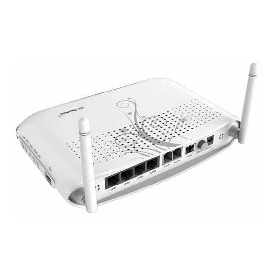
- Page 10 3 Product Overview 3 Product Overview The following introduces the appearance, specifications and indicator LEDs of the AN5506-04 Series series ONUs. 3.1 Introduction to the AN5506-04-A The AN5506-04-A is an FTTH-type GPON ONU. It provides users with communication and entertainment services in the form of data, video, and so on, to meet the integrated access demand of families and small-scaled enterprises.
- Page 11 3 Product Overview Figure 3.2 Rear Panel of the AN5506-04-A Equipment Specifications The AN5506-04-A specifications include technical parameters and specifications. See Table 3.1 for the technical parameters and see Table 3.2 for the specifications. Table 3.1 Technical Parameters of the AN5506-04-A Type Description Item...
- Page 12 3 Product Overview Table 3.1 Technical Parameters of the AN5506-04-A (Continued) Type Description Item Supports obtaining user IP address in DHCP mode; supports reporting physical location of the Ethernet interface using DHCP Option82. Supports obtaining user IP address in the PPPoE mode;...
- Page 13 3 Product Overview Table 3.2 Specifications of the AN5506-04-A Type Description Item 32mm × 170mm × 130mm Dimensions (height x width x depth). Mechanical Wall mounting hole parameters 83mm distance Weight About 240g Power supply DC 12 V/1A parameters Power consumption 6.1W parameters Operating...
- Page 14 3 Product Overview Table 3.3 Description of Indicator LEDs on the AN5506-04-A (Continued) Indicator Meaning Status Description Color Status Optical The device has not Blinking signal received the optical signal. status The device has received indicator the optical signal. The interface is connected to the user terminal and no data is transmitted.
- Page 15 3 Product Overview Figure 3.3 Overall Appearance of the AN5506-04-B The rear panel of the AN5506-04-B is shown in Figure 3.4. Figure 3.4 Rear Panel of the AN5506-04-B Equipment Specifications The AN5506-04-B specifications include technical parameters and specifications. See Table 3.4 for the technical parameters and see Table 3.5 for the specifications.
- Page 16 3 Product Overview Table 3.4 Technical Parameters of the AN5506-04-B (Continued) Type Description Item Supports the speech encoding modes such as G.711, G.723 and G.729. Supports the IEEE 802.1Q VLAN standard. Supports joining 802.1Q VLAN in tag / untag VLAN mode.
- Page 17 3 Product Overview Table 3.4 Technical Parameters of the AN5506-04-B (Continued) Type Description Item Supports global configuration of queue priority and flexible mapping of 802.1p values in packets. Supports three queue scheduling modes (PQ, WRR and PQ+WRR); supports configuring the weight of the scheduled queue, so as to guarantee the service quality of high-QoS services such as voice and video in the multi-...
- Page 18 3 Product Overview Table 3.5 Specifications of the AN5506-04-B (Continued) Type Description Item Power supply DC 12 V/1A parameters Power consumption 6.5W parameters Operating to 45 temperature Environment Storage temperature to 70 parameters Environmental 10% to 90% (no humidity condensation). Indicator LED Description See Table 3.6 for the description of indicator LEDs on the AN5506- 04-B.
- Page 19 3 Product Overview Table 3.6 Description of Indicator LEDs on the AN5506-04-B (Continued) Indicator Meaning Status Description Color Status The interface is Blinking transmitting / receiving data. The interface is not connected to the user terminal. The port is registered in the softswitch system.
- Page 20 3 Product Overview 3.3 Introduction to the AN5506-04-CG The AN5506-04-CG is an FTTH-type GPON ONU. It provides users with communication and entertainment services in the form of data, voice, video, and so on, to meet the integrated access demand of families and small-scaled enterprises.
- Page 21 3 Product Overview Figure 3.7 Side Panel of the AN5506-04-CG Equipment Specifications The AN5506-04-CG specifications include technical parameters and specifications. See Table 3.7 for the technical parameters and see Table 3.8 for the specifications. Table 3.7 Technical Parameters of the AN5506-04-CG Type Description Item...
- Page 22 3 Product Overview Table 3.7 Technical Parameters of the AN5506-04-CG (Continued) Type Description Item Supports protection against illegal message (DoS, ARP) attacks; supports suppression of broadcast storms. Supports obtaining user IP address in DHCP mode; supports reporting physical location of the Ethernet interface using DHCP Option82.
- Page 23 3 Product Overview Table 3.7 Technical Parameters of the AN5506-04-CG (Continued) Type Description Item Phone Provides two phone interfaces (RJ-11 interfaces). interface Provides one USB interface. Supports USB2.0 / interface USB1.1. Provides one CATV interface (RF interface). RF CATV output 18dBmV.
- Page 24 3 Product Overview Table 3.9 Description of Indicator LEDs on the AN5506-04-CG Indicator Meaning Status Description Color Status The device is powered Power status Power indicator Green The device is not powered on. Register The ONU is activated. status Green Activation of the ONU is indicator not yet started.
- Page 25 3 Product Overview Table 3.9 Description of Indicator LEDs on the AN5506-04-CG (Continued) Indicator Meaning Status Description Color Status The interface is connected to the user terminal and no data is Ethernet transmitted. interface LAN1 to The interface is status Green Blinking LAN4...
- Page 26 3 Product Overview 3.4 Introduction to the AN5506-04-DG The AN5506-04-DG is an FTTH-type GPON ONU. It provides users with communication and entertainment services in the form of data, video, and so on, to meet the integrated access demand of families and small-scaled enterprises.
- Page 27 3 Product Overview The rear panel of the AN5506-04-DG is shown in Figure 3.9. Figure 3.9 Rear Panel of the AN5506-04-DG The side panel of the AN5506-04-DG is shown in Figure 3.10.
- Page 28 3 Product Overview Figure 3.10 Side Panel of the AN5506-04-DG Equipment Specifications The AN5506-04-DG specifications include technical parameters and specifications. See Table 3.10 for the technical parameters and see Table 3.11 for the specifications. Table 3.10 Technical Parameters of the AN5506-04-DG Type Description Item...
- Page 29 3 Product Overview Table 3.10 Technical Parameters of the AN5506-04-DG (Continued) Type Description Item Wire- speed Supports Layer 2 / Layer 3 wire-speed forwarding. forward- Supports the IPv4/v6 dual stack. Supports the packet filtering, MAC address filtering and URL filtering. Supports protection against illegal message (DoS, ARP) attacks;...
- Page 30 3 Product Overview Table 3.10 Technical Parameters of the AN5506-04-DG (Continued) Type Description Item Provides one GPON interface (SC/UPC or SC/APC interface), supporting transmission distance up to Network GPON 20km and complying with the ITU-T G.984 standard. side interface interface Supports Class B+, with receiving sensitivity less than -29 dBm.
- Page 31 3 Product Overview Table 3.11 Specifications of the AN5506-04-DG (Continued) Type Description Item Power supply DC 12 V/1.5A parameters Power consumption parameters Operating temperature to 45 Environment Storage temperature to 70 parameters 10% to 90% (no Environmental humidity condensation). Indicator LED Description See Table 3.12 for the description of indicator LEDs on the AN5506- 04-DG.
- Page 32 3 Product Overview Table 3.12 Description of Indicator LEDs on the AN5506-04-DG (Continued) Indicator Meaning Status Description Color Status The interface is connected to the user terminal and no data is Ethernet transmitted. interface LAN1 to The interface is status Green Blinking LAN4...
- Page 33 3 Product Overview 3.5 Introduction to the AN5506-04-F The AN5506-04-F is an FTTH-type GPON ONU. It provides users with communication and entertainment services in the form of data, voice, video, and so on, to meet the integrated access demand of families and small-scaled enterprises.
- Page 34 3 Product Overview Figure 3.12 Rear Panel of the AN5506-04-F The side panel of the AN5506-04-F is shown in Figure 3.13.
- Page 35 3 Product Overview Figure 3.13 Side Panel of the AN5506-04-F Equipment Specifications The AN5506-04-F specifications include technical parameters and specifications. See Table 3.13 for the technical parameters and see Table 3.14 for the specifications. Table 3.13 Technical Parameters of the AN5506-04-F Type Description Item...
- Page 36 3 Product Overview Table 3.13 Technical Parameters of the AN5506-04-F (Continued) Type Description Item Supports up to 4095 VLANs. Supports IGMP Snooping protocol. Multicast Supports IGMP v1/v2/v3. Wire- speed Supports Layer 2 / Layer 3 wire-speed forwarding. forward- Supports the IPv4/v6 dual stack. Supports the packet filtering, MAC address filtering and URL filtering.
- Page 37 3 Product Overview Table 3.13 Technical Parameters of the AN5506-04-F (Continued) Type Description Item Supports three queue scheduling modes (PQ, WRR and PQ+WRR); supports configuring the weight of the scheduled queue, so as to guarantee the service quality of high-QoS services such as voice and video in the multi-service environment.
- Page 38 3 Product Overview Table 3.14 Specifications of the AN5506-04-F Type Description Item 36mm × 211mm × 154mm Dimensions (height x width x depth) Mechanical Wall mounting hole parameters 121mm distance Weight About 409g (5dB antenna) Power supply DC 12 V/1.5A parameters Power consumption parameters...
- Page 39 3 Product Overview Table 3.15 Description of Indicator LEDs on the AN5506-04-F (Continued) Indicator Meaning Status Description Color Status Register The ONU is activated. status Green Activation of the ONU is indicator not yet started. The device has not Optical Blinking received the optical signal...
- Page 40 3 Product Overview Table 3.15 Description of Indicator LEDs on the AN5506-04-F (Continued) Indicator Meaning Status Description Color Status The interface is not connected to the user terminal. The USB is connected. indicator Green The USB is not connected. The wireless interface is enabled.
- Page 41 3 Product Overview Appearance The overall appearance of the AN5506-04-FG is shown in Figure 3.14. Figure 3.14 Overall Appearance of the AN5506-04-FG The rear panel of the AN5506-04-FG is shown in Figure 3.15.
- Page 42 3 Product Overview Figure 3.15 Rear Panel of the AN5506-04-FG The side panel of the AN5506-04-FG is shown in Figure 3.16.
- Page 43 3 Product Overview Figure 3.16 Side Panel of the AN5506-04-FG Equipment Specifications The AN5506-04-FG specifications include technical parameters and specifications. See Table 3.16 for the technical parameters and see Table 3.17 for the specifications. Table 3.16 Technical Parameters of the AN5506-04-FG Type Description Item...
- Page 44 3 Product Overview Table 3.16 Technical Parameters of the AN5506-04-FG (Continued) Type Description Item Supports joining 802.1Q VLAN in tag / untag mode. Supports up to 4095 VLANs. Supports IGMP Snooping protocol. Multicast Supports IGMP v1/v2/v3. Wire-speed Supports Layer 2 / Layer 3 wire-speed forwarding forwarding.
- Page 45 3 Product Overview Table 3.16 Technical Parameters of the AN5506-04-FG (Continued) Type Description Item Supports three queue scheduling modes (PQ, WRR and PQ+WRR); supports configuring the weight of the scheduled queue, so as to guarantee the service quality of high-QoS services such as voice and video in the multi-service environment.
- Page 46 3 Product Overview Table 3.16 Technical Parameters of the AN5506-04-FG (Continued) Type Description Item Supports the OPEN, SHARED, WPA- PSK, WPA2-PSK and WPAPSKWPA2PSK authentication modes. Supports the TKIP, AES and TKIPAES encryption modes. Provides one USB interface. Supports USB interface USB2.0 / USB1.1.
- Page 47 3 Product Overview Table 3.18 Description of Indicator LEDs on the AN5506-04-FG Indicator Meaning Status Description Color Status Power The device is powered on. status Power Green The device is not powered indicator Register The ONU is activated. status Green Activation of the ONU is not indicator yet started.
- Page 48 3 Product Overview Table 3.18 Description of Indicator LEDs on the AN5506-04-FG (Continued) Indicator Meaning Status Description Color Status The interface is not connected to the user terminal. The USB is connected. indicator Green The USB is not connected. The wireless interface is Wireless enabled.
- Page 49 3 Product Overview Appearance The overall appearance of the AN5506-04-FS is shown in Figure 3.17. Figure 3.17 Overall Appearance of the AN5506-04-FS The rear panel of the AN5506-04-FS is shown in Figure 3.18.
- Page 50 3 Product Overview Figure 3.18 Rear Panel of the AN5506-04-FS The side panel of the AN5506-04-FS is shown in Figure 3.19.
- Page 51 3 Product Overview Figure 3.19 Side Panel of the AN5506-04-FS Equipment Specifications The AN5506-04-FS specifications include technical parameters and specifications. See Table 3.19 for the technical parameters and see Table 3.20 for the specifications. Table 3.19 Technical Parameters of the AN5506-04-FS Category Description Item...
- Page 52 3 Product Overview Table 3.19 Technical Parameters of the AN5506-04-FS (Continued) Category Description Item Supports up to 4095 VLANs. Supports the IGMP Snooping protocol. Multicast Supports IGMP v1/v2/v3. Wire-speed Supports Layer 2 / Layer 3 wire-speed forwarding forwarding. Supports the IPv4/v6 dual stack. Supports the packet filtering, MAC address filtering and URL filtering.
- Page 53 3 Product Overview Table 3.19 Technical Parameters of the AN5506-04-FS (Continued) Category Description Item Supports three queue scheduling modes (PQ, WRR and PQ+WRR); supports configuring the weight of the scheduled queue, so as to guarantee the service quality of high-QoS services such as voice and video in the multi-service environment.
- Page 54 3 Product Overview Table 3.20 Specifications of the AN5506-04-FS Category Description Item 36mm × 211mm × 154mm Dimensions (height x width x depth) Mechanical Wall mounting hole parameters 121mm distance Weight About 409g (5dB antenna) Power supply DC 12 V/1.5A parameter Power consumption...
- Page 55 3 Product Overview Table 3.21 Description of Indicator LEDs on the AN5506-04-FS (Continued) Indicator Meaning Status Description Color Status The ONU is activated. Register The ONU is being Blinking status activated. Green indicator Activation of the ONU is not yet started. The device has not Optical Blinking...
- Page 56 3 Product Overview Table 3.21 Description of Indicator LEDs on the AN5506-04-FS (Continued) Indicator Meaning Status Description Color Status The interface is connected to the user terminal and no data is Ethernet transmitted. interface LAN1 to The interface is status Green Blinking LAN4...
- Page 57 3 Product Overview 3.8 Introduction to the AN5506-04-GG The AN5506-04-GG is an FTTH-type GPON ONU. It provides users with communication and entertainment services in the form of data, voice, video, and so on, to meet the integrated access demand of families and small-scaled enterprises.
- Page 58 3 Product Overview The rear panel of the AN5506-04-GG is shown in Figure 3.21. Figure 3.21 Rear Panel of the AN5506-04-GG The side panel of the AN5506-04-GG is shown in Figure 3.22.
- Page 59 3 Product Overview Figure 3.22 Side Panel of the AN5506-04-GG Equipment Specifications The AN5506-04-GG specifications include technical parameters and specifications. See Table 3.22 for the technical parameters and see Table 3.23 for the specifications. Table 3.22 Technical Parameters of the AN5506-04-GG Type Description Item...
- Page 60 3 Product Overview Table 3.22 Technical Parameters of the AN5506-04-GG (Continued) Type Description Item Supports joining 802.1Q VLAN in the tag / untag mode. Supports up to 4095 VLANs. Supports the IGMP Snooping protocol. Multicast Supports IGMP v1/v2/v3. Wire-speed Supports Layer 2 / Layer 3 wire-speed forwarding forwarding.
- Page 61 3 Product Overview Table 3.22 Technical Parameters of the AN5506-04-GG (Continued) Type Description Item Supports three queue scheduling modes (PQ, WRR and PQ+WRR); supports configuring the weight of the scheduled queue, so as to guarantee the service quality of high-QoS services such as voice and video in the multi-service environment.
- Page 62 3 Product Overview Table 3.22 Technical Parameters of the AN5506-04-GG (Continued) Type Description Item Supports the OPEN, SHARED, WPA- PSK, WPA2-PSK and WPAPSKWPA2PSK authentication modes. Supports the TKIP, AES and TKIPAES encryption modes. Provides one USB interface; supports USB interface USB2.0 / USB1.1.
- Page 63 3 Product Overview Indicator LED Description See Table 3.24 for the description of indicator LEDs on the AN5506- 04-GG. Table 3.24 Description of Indicator LEDs on the AN5506-04-GG Indicator Meaning Status Description Color Status Power The device is powered on. status Power Green...
- Page 64 3 Product Overview Table 3.24 Description of Indicator LEDs on the AN5506-04-GG (Continued) Indicator Meaning Status Description Color Status The interface is connected to the user terminal and no data Ethernet is transmitted. interface LAN1 to The interface is transmitting / status Green Blinking...
- Page 65 3 Product Overview Table 3.24 Description of Indicator LEDs on the AN5506-04-GG (Continued) Indicator Meaning Status Description Color Status WPS is not enabled or not connected to device.
- Page 66 4 Web Configuration Guide 4 Web Configuration Guide The following introduces the Web GUI of the AN5506-04 Series ONU administrator, including the parameter meanings and operation methods. Tip: Configure the ONU using the access network management system on the OLT. Refer to the relevant OLT configuration guide.
- Page 67 4 Web Configuration Guide Table 4.1 Planning Data for Logging into the Web GUI Locally (Continued) Description Item Common user AN5506-04-A / AN5506-04-B: username: useradmin; password: user1234 AN5506-04-CG/AN5506-04-DG/AN5506-04-F/ AN5506-04-FG/AN5506-04-FS/AN5506-04-GG: See the label at the bottom of the device. Note: Some operators customized the username and password, so that the default username and password may have been modified.
- Page 68 4 Web Configuration Guide Procedure Set the IP address and the subnet mask of the computer. The operation method of the Windows 7 operating system is as follows: In the Windows taskbar, select Start Control Panel and click Network and Sharing Center. Click Local Area Connection to bring up the Local Area Connection Properties, and click Properties.
- Page 69 4 Web Configuration Guide In the Internet Protocol 4 (TCP/IPv4) Properties dialog box, set the IP address and subnet mask of the computer. (See Table 4.1 for the detailed values).
- Page 70 4 Web Configuration Guide Click the OK button to save the configuration. The operation method of the Windows XP operating system is as follows: In the Windows taskbar, select Start Control Panel. Double-click Network Connection to enter the network connection window. Right-click Local Connection and select Properties from the shortcut menu to bring up the Local Connection Properties dialog box.
- Page 71 4 Web Configuration Guide Click the OK button to save the configuration. Enter http://192.168.1.1 (default management IP address of the ONU) in the browser address bar in the computer, and press the Enter key to bring up the user login dialog box. Enter the administrator username and password in the login dialog box.
- Page 72 4 Web Configuration Guide Configuration management area. Displays the corresponding content of the selected navigation bar and link bar. (1) Navigation bar (2) Link bar (3) Configuration management area Figure 4.1 Web Configuration GUI The Web GUI configuration is basically the same for the AN5506-04 Series ONUs.
- Page 73 4 Web Configuration Guide common users. The configuration items actually available in the Web GUI for common users shall prevail. The State tab. WLAN Settings in the Network tab. Maintenance Account and Device Reboot in the Management tab. 4.2 Status The following introduces how to view the ONU basic information (including device information, WAN side status, LAN side status, optical power status, voice status and wireless network status) in the...
- Page 74 4 Web Configuration Guide 4.2.2 WAN Side Status Select State in the navigation bar and select Wan State in the left link bar to view the information such as the status, IP obtaining mode, IP address and subnet mask of the WAN side. See Figure 4.3. Figure 4.3 WAN Side Status 4.2.3 LAN Side Status...
- Page 75 4 Web Configuration Guide Figure 4.4 LAN Side Status DHCP User List Select State in the navigation bar and select Lan State DHCP Clients List in the left link bar to view the information about the DHCP client end such as the IP address, MAC address and hired time.
- Page 76 4 Web Configuration Guide Figure 4.6 Optical Power Status 4.2.5 Voice Status Select State in the navigation bar and select VOIP State in the left link bar to view the information such as the the user status and phone number. See Figure 4.7. Figure 4.7 Voice Status 4.2.6 Wireless Network Status...
- Page 77 4 Web Configuration Guide Figure 4.8 Wireless Network Status 4.3 Network The following introduces how to configure the WLAN, LAN, broadband, DHCP server, remote management, authentication and IPv6 in the Web GUI. 4.3.1 WLAN Settings The following introduces how to configure basic and advanced parameters of the wireless network, WIFI control and view of WIFI user list on the Web page.
- Page 78 4 Web Configuration Guide 4.3.1.1 Basic Configuration Configure the parameters of the wireless network such as the switch, network mode, area, band and frequency bandwidth. Select Network in the navigation bar and select Wlan Settings Basic in the left link bar to open the basic setting tab of the wireless access service, as shown in Figure 4.9.
- Page 79 4 Web Configuration Guide Table 4.2 Basic Parameters of the Wireless Network (Continued) Item Description The channel used for communication between the Frequency wireless access point and the wireless station. The (Channel) options includes AutoSelect, Channel1 to Channel13. The default setting is AutoSelect. The width of wireless band.
- Page 80 4 Web Configuration Guide Configure the parameters of the wireless network, such as the SSID, password, security mode and algorithm. See Table 4.3 for the parameter description. Click Apply to save and apply the configuration. Table 4.3 Advanced Setting Parameters of Wireless Network Item Description SSID...
- Page 81 4 Web Configuration Guide Table 4.3 Advanced Setting Parameters of Wireless Network (Continued) Item Description WPA and WPA2. This item The encryption algorithms include TKIP, AES Algo- should be and TKIPAES. rithms set if the authentica- Pass Enter the SSID key. tion mode is Phrase WPA-PSK,...
- Page 82 4 Web Configuration Guide Tip: Pressing the Apply button will validate a single SSID choice configuration item. If users does not click Apply after modifying the SSID 1 setting, the modification will not take effect. If the SSID1 setting is modified, the factory default wireless network account will be invalid.
- Page 83 4 Web Configuration Guide Configure the parameters of the wireless network, such as WIFI power and quantity of connected client ends. See Table 4.4 for the parameter description. Click Apply to save and apply the configuration. Table 4.4 Parameters of WIFI Control Item Description The Tx power of the wireless signal.
- Page 84 4 Web Configuration Guide 4.3.2.1 LAN Settings Configure the management IP address and subnet mask at the LAN side. Select Network in the navigation bar and select LAN Settings LAN Settings in the left link bar to open the LAN settings tab, as shown in Figure 4.13.
- Page 85 4 Web Configuration Guide Select Network in the navigation bar, and select LAN Settings CATV RF Power in the left link bar to open the RF output level adjustment tab, as shown in Figure 4.14. Figure 4.14 RF Output Level Adjustment Enter the RF output level adjustment range.
- Page 86 4 Web Configuration Guide Figure 4.15 Broadband Setting Configure parameters relevant to the broadband at the WAN side. Table 4.6 describes the parameters. Click Apply to save and apply the configuration. Table 4.6 Parameters for Broadband Settings Description Item Select the WAN port service type. TR069: this connection is only applicable for TR069.
- Page 87 4 Web Configuration Guide Table 4.6 Parameters for Broadband Settings (Continued) Description Item multicast: this connection is applicable for TR069, voice and Internet access. VOIP: this connection is only applicable for voice application. VOIP_INTERNET: this connection is applicable for voice and Internet access.
- Page 88 4 Web Configuration Guide Table 4.6 Parameters for Broadband Settings (Continued) Description Item SSID Select the wireless SSID to be bound with the WAN port. Binding Users need to configure this item when the service type is set to Enables or disables the IPv6 function. IPv6 INTERNET, TR069_ The default setting is Disable.
- Page 89 4 Web Configuration Guide Table 4.6 Parameters for Broadband Settings (Continued) Description Item period expires. Enter the static IP address at the WAN side provided by ISP. Address Subnet Enter the subnet mask provided by ISP. Mask Default This item should be Enter the default gateway provided by Gateway configured when the...
- Page 90 4 Web Configuration Guide Table 4.6 Parameters for Broadband Settings (Continued) Description Item This item should be IPv6 set when IPv6 is Select the IPv6 address obtaining mode / Addres- enabled and the prefix obtaining mode. s/Prefix WAN IP Mode is set to DHCP or PPPoE.
- Page 91 4 Web Configuration Guide Configure the DHCP server parameters as required. Table 4.7 describes the parameters. Click Apply to save the configuration information. The configuration will take effect after the ONU is rebooted. Table 4.7 Parameters for the DHCP Server Item Description Enables or disables the DHCP server.
- Page 92 4 Web Configuration Guide Table 4.7 Parameters for the DHCP Server (Continued) Item Description DHCP The lease time of the IP address pool of the DHCP server. Lease Time Enables or disables the Option 60 property to identify the user Option60 terminal.
- Page 93 4 Web Configuration Guide Figure 4.17 TR-069 Configuration Configure relevant parameters according to the requirement. Table 4.8 shows the parameter description. Click Apply to save and apply the configuration. Table 4.8 Parameters for TR-069 Configuration Item Description Enables or disables the TR069 function. After the aforesaid operation, click the Apply button to validate the TR069Enable configuration.
- Page 94 4 Web Configuration Guide Table 4.8 Parameters for TR-069 Configuration (Continued) Item Description Connection Enables or disables the user authentication when the ACS Request sends the connection request to the ONU. Authentication Connection Authentication username of the ACS sending the Request connection request to the ONU.
- Page 95 4 Web Configuration Guide Figure 4.18 OLT Authentication Configure the parameters as required. Table 4.9 describes the parameters. Click Apply to save the configuration information. The configuration will take effect after the ONU is rebooted. Table 4.9 Parameters for OLT Authentication Item Description Logic SN...
- Page 96 4 Web Configuration Guide Figure 4.19 IPv6 Static Routing Configure the parameters relevant to static routing as required. Table 4.10 describes the parameters. Click Apply to save and apply the configuration. Table 4.10 Parameters for the IPv6 Static Routing Item Description The destination IP address to be accessed by the host.
- Page 97 4 Web Configuration Guide 4.4.1 Firewall The firewall configuration includes Firewall enabling IP filtering IPv6 filtering URL filtering Anti-port scan DHCP filtering MAC address filtering IPv6 Mac filtering 4.4.1.1 Firewall Enabling Enabling firewall can prevent the malicious access to the WAN port of the ONU.
- Page 98 4 Web Configuration Guide 4.4.1.2 IP Filtering Allow or forbid the incoming or outgoing flow of the IP packets that comply with the filtering conditions. After the firewall is enabled, the pre-set rules will take effect. Select Security in the navigation bar and select Firewall IP Filtering in the left link bar.
- Page 99 4 Web Configuration Guide Table 4.11 Parameters for IP Address Filtering Item Description Select the uplink filtering mode. Whitelist indicates that the data complying with the rules in the filtering Uplink rule table will be allowed to pass. After the Blacklist indicates that the data aforesaid complying with the rules in the filtering...
- Page 100 4 Web Configuration Guide 4.4.1.3 IPv6 Filtering Allow or forbid the IPv6 messages that comply with the filtering condition to be transmitted from the LAN or transmitted into MAN. After the firewall is enabled, the pre-set rules will take effect. Select Security in the navigation bar and select Firewall IPv6 Filtering in the left link bar.
- Page 101 4 Web Configuration Guide Table 4.12 Parameters of IPv6 Filtering Item Description Select the uplink filtering mode. Whitelist indicates that the data complying with the rules in the filtering Uplink rule table will be allowed to pass. After the Blacklist indicates that the data aforesaid complying with the rules in the filtering operation, click...
- Page 102 4 Web Configuration Guide 4.4.1.4 URL Filtering By setting the URL filtering rules, users can forbid or allow all the data packets sent to or received from a certain IP address. After the fire wall is enabled, the pre-set URL filtering rule will take effect, and the domain names that meet the filtering conditions will be filtered.
- Page 103 4 Web Configuration Guide Table 4.13 Parameters for URL Filtering Parameters Item Description Enables or disables the URL filtering Enable function. Select the filtering mode. The white list and black list modes are global configuration, which cannot be enabled simultaneously. After setting, Whitelist indicates that the data click Apply...
- Page 104 4 Web Configuration Guide Figure 4.24 Anti-port Scan Select to Enable or Disable the anti-port scan function as required. Click Apply to save and apply the configuration. 4.4.1.6 DHCP Filtering Forbid or allow the user device configured with the MAC address to obtain an IP address in the DHCP mode to prevent DOS attacks.
- Page 105 4 Web Configuration Guide Configure the parameters relevant to filtering as required. Table 4.14 describes the parameters. Click Apply to save and apply the configuration. Table 4.14 Parameters for DHCP Filtering Item Description DHCP Enables or disables the DHCP filtering. Filtering Enable Select the filtering mode.
- Page 106 4 Web Configuration Guide Figure 4.26 MAC Addresses Filtering Configure parameters relevant to filtering as required. Table 4.15 describes the parameters. Click Apply to apply and save the configuration. Table 4.15 Parameters for MAC Address Filtering Item Description Enables or disables the MAC address Filtering filtering function.
- Page 107 4 Web Configuration Guide Table 4.15 Parameters for MAC Address Filtering (Continued) Item Description filtering rule table will not be allowed to pass. The MAC address in the MAC address filtering rule. Address The starting time of the filtering rule. Start Time The ending time of the filtering rule.
- Page 108 4 Web Configuration Guide Figure 4.27 IPv6 Mac Filtering Configure the parameters relevant to filtering as required. Table 4.16 describes the parameters. Click Apply to save and apply the configuration. Table 4.16 Parameters for IPv6 MAC Address Filtering Item Description Enables or disables the MAC address Filtering filtering function.
- Page 109 4 Web Configuration Guide Table 4.16 Parameters for IPv6 MAC Address Filtering (Continued) Item Description filtering rule table will not be allowed to pass. The MAC address in the MAC address filtering rule. Address The starting time of the filtering rule. Start Time The ending time of the filtering rule.
- Page 110 4 Web Configuration Guide 4.4.3 Route QoS The route QoS includes route QoS enabling and route QoS configuration. 4.4.3.1 Route QOS Enable Enable / disable the route QOS function. Select Security in the navigation bar and select Route QOS QOS Enable in the left link bar to open the route QOS enabling tab, as shown in Figure 4.29.
- Page 111 4 Web Configuration Guide Figure 4.30 Route QoS Configuration Configure the parameters relevant to QoS according to the requirement. Table 4.17 describes the parameters. Click Apply to save and apply the configuration. Table 4.17 Parameters of Route QoS Configuration Item Description Type Select the priority type.
- Page 112 4.4.4 WPS WPS can automatically set the network name (SSID) and wireless encryption key for the AN5506-04 Series ONUs and the client end supporting the Wi-Fi service. Users need only to press down the WPS button or enter PIN to achieve safe connection. Users need not remember the long encryption key and are free of the trouble caused by forgetting the password.
- Page 113 4 Web Configuration Guide 4.4.5 ACL Configuration Users can configure ACL (Access Control List) to filter designated data packets using the matching rules. After the ACL rule is enabled, the corresponding port will filter the packets as per the configured ACL rules.
- Page 114 4 Web Configuration Guide Figure 4.33 ACL Configuration Rule Configure parameters relevant to filtering as required. Table 4.18 describes the parameters. Click Submit to generate the corresponding ACL rule item. Click Apply to save and apply the configuration. Table 4.18 Parameters for ACL Configuration Item Description...
- Page 115 4 Web Configuration Guide Table 4.18 Parameters for ACL Configuration (Continued) Item Description The options include IP, IP+Mac and IP ACL Type +Mac+Vid. Modifying ACL type will delete all the existing ACL rules. The number of the LAN port(s) subject to the ACL rule. The Port options include ALL and 1 to 4.
- Page 116 4 Web Configuration Guide Click Apply to save and apply the configuration. 4.4.7 HTTPS The ONU provides the HTTPS function. The HTTPS is the HTTP channel for security. It is built on the SSL+HTTP protocol, which can perform encryption transmission and identity authentication. Select Security in the navigation bar and select HTTPS in the left link bar to open the HTTPS function configuration tab, as shown in Figure 4.35.
- Page 117 4 Web Configuration Guide 4.5.1 VPN Set whether to enable the VPN transparent transmission channel. Select Application in the navigation bar and select VPN in the left link bar to open the VPN transparent transmission configuration tab, as shown in Figure 4.36. Figure 4.36 VPN Transparent Transmission Select to Enable or Disable the transparent transmission as...
- Page 118 4 Web Configuration Guide Figure 4.37 DDNS Settings Configure parameters relevant to DDNS according to the requirement. Table 4.19 describes the parameters. Click Apply to apply and save the configuration. Table 4.19 Parameters for DDNS Settings Item Description The username allocated by the DDNS provider. Username The password allocated by the DDNS provider.
- Page 119 4 Web Configuration Guide 4.5.3 Port Forwarding The port forwarding can create the mapping relation between the WAN port IP address / common port number and the LAN server IP address / private port number. In this way, all the accesses to a certain service port at this WAN port will be re-directed to the corresponding port of the server in the designated LAN.
- Page 120 4 Web Configuration Guide Table 4.20 Parameters for Port Forwarding (Continued) Item Description Description The port forwarding rule name. The range of ports for Extranet data packets. If only one Public Port port exists, enter the same port number. The IP address of the LAN virtual server for port forwarding.
- Page 121 4 Web Configuration Guide Figure 4.39 Port Triggering Configure parameters relevant to port triggering according to the requirement. Table 4.21 describes the parameters. Click Apply to apply and save the configuration. Table 4.21 Parameters for Port Triggering Item Description The corresponding WAN connection bound with the port triggering rule.
- Page 122 4 Web Configuration Guide 4.5.5 NAT NAT can implement the conversion between intranet IP addresses and public network IP addresses. NAT converts a great number of intranet IP addresses into one or a small number of public network IP addresses, so as to save the resource of public network IP addresses.
- Page 123 4 Web Configuration Guide Table 4.22 Parameters for NAT Configuration Item Description The corresponding WAN connection bound with the NAT rule. Description NAT rule name. Select the NAT conversion mode. It is advisable to select Rule Type One-to-One or Many-to-One. The starting IP address of intranet.
- Page 124 4 Web Configuration Guide Figure 4.41 UPnP Select to Enable or Disable the UPnP function as required. Click Apply to save and apply the configuration. 4.5.7 DMZ When the ONU is working in the routing mode, users should enable the DMZ function if a host at the WAN side needs to access a certain host at the LAN side.
- Page 125 4 Web Configuration Guide Table 4.23 Parameters for DMZ Configuration Item Description Enables or disables the DMZ function. The options include Enable, Disable and Auto. If Enable is selected, the DMZ DMZ Enable host IP address should be set. If Auto is selected, the DMZ host uses the first IP address allocated by DHCP.
- Page 126 4 Web Configuration Guide 4.6 Management The following introduces how to perform user management, device management and log query in the Web GUI. 4.6.1 User Management User management includes user account management and maintenance account management. 4.6.1.1 User Account Management Users can add or delete a common user account or modify the password of a common user account.
- Page 127 4 Web Configuration Guide 4.6.1.2 Maintenance Account Management Users can modify the username and password of the current account. Select Management in the navigation bar. Select Account Management Maintenance Account from the left link bar to open the maintenance account management tab, as shown in Figure 4.45.
- Page 128 4 Web Configuration Guide 4.6.2.1 Restoring the Configuration Data Restore the configuration of the ONU to the factory configuration, such as Web login username and password, and wireless network SSID and password. Select Management in the navigation bar. Select Device Management Restore from the left link bar to open the restoring tab, as shown in Figure 4.46.
- Page 129 4 Web Configuration Guide Click Browse. In the dialog box that appears, select the device software version to be upgraded and click Open to upgrade the ONU software version. When the upgrade succeeds, the page will prompt for device rebooting. Click Reboot. After rebooting, the device will be upgraded to the new version.
- Page 130 4 Web Configuration Guide Table 4.24 Parameters for Configuration Backup Item Description Username The FTP username. The FTP password. Password Localhost IP Local IP address. The existing file name in the ONU. File Name 4.6.2.4 FTP Client End The ONU serves as the FTP client end. Users can upload files to the FTP server or download files from the FTP server.
- Page 131 4 Web Configuration Guide Table 4.25 Parameters for the FTP Client End Item Description Type Select to upload or download. Username The FTP server username. The FTP server password. Password FTP Server IP The FTP Server IP address. The FTP server port. FTP Server Port Remote File Name The name of file saved in the FTP server.
- Page 132 4 Web Configuration Guide Click Apply to save and apply the configuration. 4.6.2.6 Device Reboot Select Management in the navigation bar. Select Device Management Device Reboot from the left link bar to open the device reboot tab, as shown in Figure 4.51. Figure 4.51 Device Reboot Click Reboot and click OK in the alert box that appears and...
- Page 133 4 Web Configuration Guide Figure 4.52 NTP Time Calibration Configure relevant parameters relevant to the NTP time calibration. Table 4.26 describes the parameters. Click Check Time to save and apply the configuration. Table 4.26 Parameters for NTP Time Calibration Item Description Enable NTP Check Select whether to enable the NTP time calibration...
- Page 134 4 Web Configuration Guide Figure 4.53 View or download the saved information according as needed.
- Page 135 5 Handling Common Problems 5 Handling Common Problems The following introduces how to handle common router faults. 5.1 The Power Indicator LED Remaining Handle according to the procedures below. Check whether the mains supply is normal. Check whether the power adapter matches the device. Check whether the power button is pressed down.
- Page 136 5 Handling Common Problems Check whether the optical fiber is damaged. Check whether the optical fiber is connected to the correct interface. Check whether the Rx optical power of the ONU is over-low (using the optical power meter). Check whether the ONU optical module is aged or damaged. Check whether the local device is faulty.
- Page 137 5 Handling Common Problems between the ONU and the wireless terminal is within the required range.
- Page 138 Appendix A Standard and Protocol Appendix A Standard and Protocol Standard Type Title Number Gigabit-capable passive optical networks ITU-T G.984.1 (GPON): General characteristics Gigabit-capable Passive Optical Networks (GPON): Physical Media Dependent (PMD) ITU-T G.984.2 layer specification GPON Gigabit-capable Passive Optical Networks (G-PON): Transmission convergence layer ITU-T G.984.3 specification...
- Page 139 Appendix A Standard and Protocol Standard Type Title Number IEEE Standard for Local and Metropolitan Area Networks Virtual Bridged Local Area IEEE 802.1ag- Networks Amendment 5: Connectivity Fault 2007 Management IEEE Standard for Information technology - Telecommunications and information exchange between systems - Local and metropolitan area networks - Specific IEEE 802.3- requirements Part 3: Carrier Sense Multiple...
- Page 140 Appendix A Standard and Protocol Standard Type Title Number Coding of speech at 8 kbit/s using conjugate- structure algebraic-code-excited linear ITU-T G.729 prediction (CS-ACELP) G.729 based Embedded Variable bit-rate coder: An 8-32 kbit/s scalable wideband ITU-T G.729.1 coder bitstream interoperable with G.729 Implementers' Guide for G.729 Annexes B, F, ITU-T G.Imp G, I and C+ (Coding of speech at 8 kbit/s...
- Page 141 Appendix A Standard and Protocol Standard Type Title Number Information technology equipment - Radio CISPR 22 disturbance characteristics - Limits and (EN55022) methods of measurement Information technology equipment - Immunity CISPR 24 characteristics - Limits and methods of (EN55024) measurement CPE WAN Management Protocol Other TR-069...
- Page 143 Product Documentation Customer Satisfaction Survey Thank you for reading and using the product documentation provided by FiberHome. Please take a moment to complete this survey. Your answers will help us to improve the documentation and better suit your needs. Your responses will be confidential and given serious consideration.
- Page 144 Thank you for your assistance. Please fax or send the completed survey to us at the contact information included in the documentation. If you have any questions or concerns about this survey please email at edit@fiberhome.com.
- Page 146 FiberHome Telecommunication Technologies Co., Ltd. Address: No. 88 Youkeyuan Rd., Wuhan, Hubei, China Zip code: 430074 Website: www.fiberhomegroup.com...
Need help?
Do you have a question about the AN5506-04 Series and is the answer not in the manual?
Questions and answers
Здравствуйте. Что означает: Функция CATV не является при включенном режиме сигнал CATV является не принят или сигнал отключен.бедный. Как подключить ТВ?
The message "CATV function is not available, CATV signal is not received or signal is disconnected" for the FiberHome AN5506-04 Series means one of the following:
- The CATV (Cable TV) function is turned off.
- The CATV signal is weak or not present.
- The CATV cable is not connected properly.
To connect the TV:
1. Make sure the CATV cable is connected to the CATV port on the device.
2. Check that the CATV service is enabled by your service provider.
3. Confirm the CATV indicator LED:
- Green (Blinking): Signal is poor.
- Green (On): Signal is normal.
- Off: No signal or CATV function is disabled.
Ensure the cable is secure and contact the provider if the signal is not restored.
This answer is automatically generated