
Related Manuals for FiberHome AN5516-04


Summary of Contents for FiberHome AN5516-04
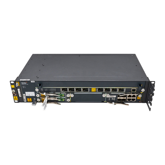
- Page 1 AN5516-04 Optical Line Terminal Equipment Quick Installation Guide Version : D MN000003108...
- Page 3 No part of this document (including the electronic version) may be reproduced or transmitted in any form or by any means without prior written permission from FiberHome. Information in this document is subject to change without notice. All rights reserved...
-
Page 5: Installation Procedure
Installation Procedure Operation procedure Start Safety Reference information Page 2 precautions Page Specifications and Pages Installation precautions for Page 4 card operations preparations Operation rules for plugging / Page 5 unplugging optical modules Installing Page 6 cabinets Subrack Page 6 overview Pages Installing... -
Page 6: Safety Precautions
Safety Precautions Warning Laser Safety To prevent laser radiation from injuring eyes, do not look into the Laser class end face of the fiber or fiber connector directl ly with naked eyes. identifier Caution ESD Protection Carpets or other materials that easily gene ... -
Page 7: Installation Tools
Installation Tools Ladder Vacuum cleaner Electric drill Drilling bit Long tape Marker pen Spirit level File Knife Cross screwdriver Flat screwdriver Claw hammer Sharp nose pliers Crimping pliers Diagonal pliers Wire stripper Fiber puller Torque wrench Combination wrench M6 to M12 socket wrench Multimeter Optical power meter Network cable tester... -
Page 8: Card Operations
Specifications and Precautions for r Card Operations Caution Do not contact cards with bare hands. Alw ways wear ESD protection gloves or ESD protection wrist strap when operating on cards. When holding a card, put your hands on it ts panel, and do not touch any component or wires on cards, or metal conductors in sockets. - Page 9 Operation Rules for Plugging / Un plugging Optical Modules Plugging the Optical Module Hold the optical module, and plug it into the card along the EMI cage. Material Order number number Working wavelength Transmission distance 防 静 Rate 电 手 套...
-
Page 10: Installing Cabinets
Installing Cabinets Note The AN5516-04 can be installed in the follow wing cabinets. Please refer to the following manuals for the procedures of installing the cabinets. Cabinet Model Manual D Description 19-inch cabinets (4102596 to Quick Ins stallation Guide for the 19-inch Cabinet (600 mm-deep) -
Page 11: Equipment Layout
Equipment Layout Rules for Arranging Subracks When multiple AN5516-04 subracks are to be i nstalled in a cabinet, usually arrange them from the top down. The AN5516-04 subrack supports both DC pow wer supply and AC power supply. The equipment layouts in the two cases are different. - Page 12 Example of Arranging Subracks in a 21-inch Cabin net (AC Power Supply) Unit: mm Example of Arranging Subracks in a 21-inch Cabin 21 i h C bi net (DC Power Supply) t (DC P Unit: mm...
- Page 13 Installing Subrack in 19-inch Cabinet Installing Components Slide rails for 19-inch cabinets Mark the positions for mounting the Install the slide rails. subrack and slide rails on the vertical mounting flanges of the cabinet. Then Panel screw install the floating nuts. Panel screw Push the subrack into the cabinet along the slide rails.
- Page 14 Installing Subrack in 21-inch Cabinet Installing Components Adapter mounting ears Slide rails for 21-inch cabinets Installation steps Installation steps Mark the positions for mounting Install the slide rails. the slide rails and subracks on the Panel screw vertical mounting flanges of the cabinet.
- Page 15 Rear side of the ≥30 Unit: mm subrack Wall mounting ears ≥80 ≥80 AN5516-04 (1) Hex machine screw M8x60 (2) Spring washer ≥300 Front side of (3) Flat washer the subrack ≥60...
- Page 16 Installing Cards and Components Installing Cards Caution ESD protection gloves / wrist strap Before installing a card, check the pin and d card connector on the backplane. Follow the rules for installing cards. If resistance is encountered when you are plugging a card, pull Cross Captive...
- Page 17 The AN5516 04 can use the PDP296B (3 The AN5516-04 can use the PDP296B (3 000068) Please refer to Hardware Description for the 000068). Please refer to Hardware Description for the specifications and pin definitions of the PD ...
- Page 18 Cabinet with Routed Fibers and C Cables A PON Service Subrack An MSAN Service Subrack 1 14...
-
Page 19: Ground Cable
Connecting Power Cables and Pro otection Earth Ground Cables 11.1 Connecting the Cabinet Protection Earth h Ground Cable Cling one end of the cabinet protection earth gr round cable to the earth ground point on the cabinet top and tighten it with a screw. Lead the e other end of the cable to the earth ground point on the head of row cabinet in the equipme ent room. - Page 20 Connection PDP End Cable Note 1 Opposite End PDP296B (3000068) -48V power cable e (blue) -48V_A terminal (active) External -48V DC power -48V_B terminal (standby) supply 0V power cable (b black) 0V_A terminal (active) External power earth ground 0V_B terminal (standby) PDP protection ea arth ground cable (yellow- /green)
- Page 21 view Wiring hole nnect the cabinet earth ground cable to protection earth ground bar in the uipment room. ad the power cable into the cabinet. Remove the front panel of the PDP. Connect the terminals of cabinet power cables on the PDP side and the opposite end.
- Page 22 11.3 Connecting the Subrack Protection Eart th Ground Cable Flat Cross Marker pen Panel screw Subrack protection earth ground cable screwdriver screwdriver Uninsulated ring tongue crimped terminal Uninsulated ring tongue crimped terminal Cling the uninsulated ring tongue crimped terminal on one end of the protection earth ground cable to the earth ground hole on the subrack and secure it with a panel screw with a flat...
- Page 23 Connect the blue and black cord end terminals of the subrack power cable to the corresponding interfaces on the PDP. Connection of the subra ck power cables for the AN5516-04 on the PDP side may vary with the PDP used. Refer to the table below for details.
- Page 24 Connecting the Alarm Cable 12.1 Connecting the Subrack Alarm Cable Insert the RJ-45 connector on one end of the s subrack alarm cable into the ALARM socket on the HSUB / HSUC card. Lead the other end of the subrack alarm cable e through the fiber guide unit.
- Page 25 Connecting the E1 Cable Cross screwdriver Thread the E1 cable through the wiring hole at the Connected top of the cabinet, and route it downward along the to the DDF wiring channel at the side of the cabinet. Lead the E1 cable through the fiber passage unit on the subrack, and route it to the CE1B card.
- Page 26 Connecting the 64-conductor Aud io Interface Cable Connected to MDF Cross screwdriver Lead the 64-conductor audio interface cable through the wiring hole on the top of the cabinet, and route it downward along the wiring channel on the side of the cabinet. Lead the 64-conductor audio interface cable through the fiber passage unit...
-
Page 27: Connecting The Network Cable
Connecting the Network Cable Connection Subrack Side (RJ-45) Interface Opposite End (RJ-45) HSUB/HSUC card Connected to the UNM2000 computer . TIMA card 1000MASK_TX Connected to the opposite end equipment . HSUB/HSUC card BITS/TOD Connected to the BITS/TOD external clock source. Connected to the oppo osite end equipment e on the cabinet top, and route it downward along the... - Page 28 Select the right type of the optical fiber jumpe r according to the type of the optical interfaces on the local equipment and opposite end equipment. . The optical interfaces on the AN5516-04 correspond to two types of optical fiber connectors: LC/PC C and SC/PC (SC/APC).
- Page 29 17.2 Connecting the Optical Fiber Inside the Cabinet Caution Bind all wires and cables used in onsite in nstallation. Each cable type should be bound separately. For example, power cables, a larm cables and optical fibers should be laid out independently and bound separately.
- Page 30 Connecting the Serial Port Line Note The serial port line is used to connect the C ONSOLE / ESC interface of the HSUC / HSUB card and the serial port of the local compute er. It is used only in commissioning or debugging. Insert the RJ-45 connector of the serial port li ine into the CONSOLE / ESC interface of the HSUC / HSUB card.
-
Page 31: Post Installation Inspection
Installing the Cabinet Door Note The AN5516-04 can be installed in the follow wing cabinets. Please refer to the following manuals for the procedures of installing the c cabinet doors. Caution Exercise care in operation especially when cl losing or opening the doors to avoid damage to the cables. -
Page 32: Checking Before Power-On
20.2 Checking before Power-on Caution The AN5516-04 uses -48 V DC power supply y with an acceptable voltage range from -40 V to -57 V. Before powering on the equipment, installers should 1. Confirm that the cabinet power cables are correctly connected with the external power supply equipment. -
Page 33: Do's And Don'ts
Dos and Don’ts Direct or indirect contact Promptly report any (through damp objects) with Do not install / operate the Do not connect or remove conditions that may lead to high voltage power supply equipment or lay cables the power cable while it is security problems. - Page 36 Address: No. 67, Guanggu Changye Jie, Wuhan, Hubei, China Zipcode: 430073 Tel: +6 03 7960 0860/0884 (for Malaysia) +91 98 9985 5448 (for South Asia) +593 4 501 4529 (for South America) Fax: +86 27 8717 8521 Website: http://www.fiberhomegroup.com Copyright©FiberHome Telecommunication Technologies Co., Ltd.
Need help?
Do you have a question about the AN5516-04 and is the answer not in the manual?
Questions and answers