FiberHome AN5506-01-A User Manual
Gpon optical network unit
Hide thumbs
Also See for AN5506-01-A:
- Product manual (78 pages) ,
- User manual ,
- Product manual (44 pages)

Related Manuals for FiberHome AN5506-01-A


Summary of Contents for FiberHome AN5506-01-A
- Page 1 An Expert in Optical Communications User Manual AN5506-01-A GPON Optical Network Unit Version: A Code: MN000000943 Date: December 2011 FiberHome Telecommunication Technologies Co., Ltd.
- Page 2 Description Initial version are trademarks of FiberHome Telecommunication Technologies Co., Ltd. (Hereinafter referred to as FiberHome) All brand names and product names used in this document are used for identification purposes only and are trademarks or registered trademarks of their respective holders.
- Page 3 Operation Safety Rules High optical power can cause bodily harm, especially to eyes. Never look directly into the end of the optical transmitter fiber jumper or the end of its active connector. Exercise care if you must bend fibers. If bends are necessary, the fiber bending radius should never be less than 38mm.
- Page 4 Packing List When unpacking the AN5506-01-A, please check that all items in the packing list below are present. Name Number Remark — AN5506-01-A — Conformity certificate Contains an AN5506-01-A Document bag GPON Optical Network Unit User Manual. The AN5506-01-A is equipped...
-
Page 5: Table Of Contents
Contents 1 Product Description............. 1 1.1 Product Function ............... 1 1.2 Product Type ..............2 1.3 Technical Specification ............2 2 Product Appearance ............ 5 2.1 Front Panel and Indicator LEDs ........5 2.2 Rear Panel and Interface ..........7 3 Product Installation............ -
Page 7: Product Description
Below is the network diagram of the AN5506-01-A. Figure 1-1 Network diagram of the AN5506-01-A As shown in Figure 1-1, the AN5506-01-A is used together with the AN5516-01 (OLT). They together make up a GPON system that provides a large-capacity, high-reliability multi-service access network. -
Page 8: Product Type
Power Supply interface interface Jack — AN5506-01-A 2-conductor power socket. 1.3 Technical Specification Table 1-2 lists the technical specifications of the AN5506-01-A. Table 1-2 Technical specifications of the AN5506-01-A Type Item Description Service VLAN Supports the IEEE 802.1Q VLAN standard;... - Page 9 1 Product Description Type Item Description The full 4096 VLAN address space is supported. MAC address The MAC address table size is 64. Supports IGMP Snooping and IGMP Multicast Proxy protocols; Supports IGMP v1 / v2 / v3. Wire speed All interfaces support the wire speed L2 / L3 forwarding.
- Page 10 1 Product Description Type Item Description Environmental 10% to 90%, non-condensing humidity...
-
Page 11: Product Appearance
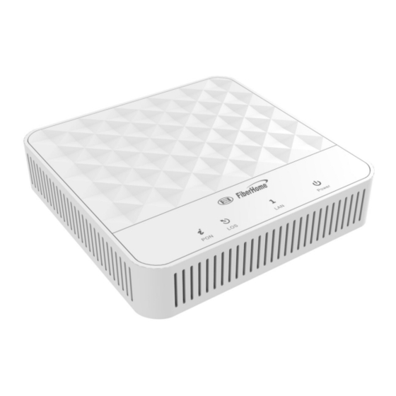
2 Product Appearance 2 Product Appearance 2.1 Front Panel and Indicator LEDs The AN5506-01-A has a streamline design with novel and fashionable appearance. The LED indicators on the front panel show the operating status of the equipment, thereby the users can learn about the status directly. - Page 12 2 Product Appearance Table 2-1 Description for the AN5506-01-A indicator LEDs Name Meaning Color Status Description Power Power status Green The equipment is powered indicator on via the 2-conductor DC power supply. equipment powered on. Registration Green The equipment is registered status to the GPON system.
-
Page 13: Rear Panel And Interface
2.2 Rear Panel and Interface With all interfaces and buttons distributed on the rear panel, the AN5506-01-A has a simple model that is convenient for use. As shown in Figure 2-2, the interfaces and buttons from left to right are: power switch, power interface, reset button, Ethernet interface (×1) and PON interface. -
Page 14: Product Installation
3 Product Installation 3.1 Preparation 3.1.1 Unpacking Check When unpacking the AN5506-01-A, please check that all items on the list are present and not damaged. If any item is missing or has been damaged, please contact local agencies of FiberHome immediately. -
Page 15: Equipment Mounting
3 Product Installation 3.2 Equipment Mounting The AN5506-01-A can be either secured on a stable plane like an office desk or hung vertically against the wall based on your demand. The two mounting methods are introduced below: Desk top mounting Step 1 Take out the AN5506-01-A from the carton. -
Page 16: Cable And Wire Connection
3 Product Installation 3.3 Cable and Wire Connection 3.3.1 Connecting Optical Fiber Jumper Cable and wire description The PON interface of the AN5506-01-A can be uplinked to the central office end OLT equipment via the optical fiber. Connection procedures Step 1 Plan the layout of the optical fiber jumper. -
Page 17: Connecting Network Cable
Figure 3-1 Connection diagram for optical fiber 3.3.2 Connecting Network Cable Cable and wire description The Ethernet interface of the AN5506-01-A is connected to the user’s PC and the switch via network cables to access data service. Connection procedures Step 1 Plan the layout of the network cable. - Page 18 The transmission distance of the network cable is shorter than 100m. Therefore, the network cable you prepare should not exceed 100m. Note 2: The Ethernet interface of the AN5506-01-A supports the MDI / MDIX self-adaption. You can use the straight-through or cross- over network cable for connection. Connection diagram...
-
Page 19: Connecting Power Cable
3 Product Installation 3.3.3 Connecting Power Cable The AN5506-01-A uses a 2-conductor power adapter. Connection procedures Step 1 Take out the DC power adapter with two conductors provided in the AN5506-01-A package. Step 2 Insert the plug at one end of the adapter into the 12V DC interface of the AN5506-01-A. - Page 20 Otherwise, check whether the network cable is correctly connected. Step 5 During the equipment operation, ensure the ventilation to avoid abnormal events caused by overheating. When any abnormality occurs, contact the local office of FiberHome for replacement.
-
Page 21: Faqs
4 FAQs 4 FAQs All indicator LEDs are extinguished after power-on. 1. Check whether the power cable is correctly connected; Check whether the power switch on the equipment’s rear panel is in the ON position. The equipment fails to work. 1.
Need help?
Do you have a question about the AN5506-01-A and is the answer not in the manual?
Questions and answers