
Related Manuals for FiberHome AN6000-17


Summary of Contents for FiberHome AN6000-17
- Page 1 AN6000-17 Optical Line Terminal Equipment Hardware Description Version: A Code: MN000003536 FiberHome Telecommunication Technologies Co., Ltd. December 2018...
- Page 3 Please contact your local sales representative, service representative or distributor for any help needed at the contact information shown below. Fiberhome Telecommunication Technologies Co., Ltd. Address: No. 67, Guanggu Chuangye Jie, Wuhan, Hubei, China Zip code: 430073...
- Page 5 Legal Notice are trademarks of FiberHome Telecommunication Technologies Co., Ltd. (Hereinafter referred to as FiberHome) All brand names and product names used in this document are used for identification purposes only and are trademarks or registered trademarks of their respective holders.
-
Page 7: Table Of Contents
Contents Documentation Guide ..................1 Subrack......................3 Subrack Model and Specifications.............4 Subrack Structure ................5 Fan Unit....................6 Slot Distribution and Cards Supported..........8 Cards ......................9 Card Structure ................10 Card Overview................11 Core Switch Card................12 3.3.1 HSCA ................12 Uplink Card..................17 3.4.1 KU1A ................17 3.4.2 HU8A ................21 Power Card ..................24 3.5.1 PIBA.................24... - Page 8 4.2.1 10G EPON Optical Module ..........43 4.2.2 GPON Optical Module ............43 4.2.3 XG-PON Optical Module ...........44 4.2.4 Combo PON Optical Module ..........44 Ethernet Module ................45 4.3.1 GE Module ...............46 4.3.2 10GE Optical Module............48 4.3.3 100G Optical Module ............50 Wires and Cables ..................51 Cable Overview ................52 Power Cable...................52 5.2.1...
-
Page 9: Documentation Guide
Document Orientation Hardware Description gives a detailed introduction to the hardware components of the AN6000-17. This manual is designed for readers who want to have a detailed knowledge about the hardware of the equipment or need the hardware information to guide their operation and maintenance of the equipment. - Page 10 AN6000-17 Optical Line Terminal Equipment Hardware Description Chapter Summary Cabinet overview Appearances and detailed dimensions of the cabinets Cabinet Equipment layout PDP overview Panel and terminals of the PDP Related Documentation Applied to Document AN6000-17 Optical Line Terminal Equipment Network planning phase...
-
Page 11: Subrack
Subrack Subrack Model and Specifications Subrack Structure Fan Unit Slot Distribution and Cards Supported Version: A... -
Page 12: Subrack Model And Specifications
AN6000-17 Optical Line Terminal Equipment Hardware Description Subrack Model and Specifications Model The model number of the AN6000-17 subrack is 3061146. Dimensions Item Specification Dimensions of the subrack with mounting ears for 21- 486 mm × 530 mm × 282 mm inch cabinets (H ×... -
Page 13: Subrack Structure
2 Subrack Maximum power consumption: all the broadband ports are concurrently activated. Maximum Static Power Typical Power Typical Configuration Power Consumption Consumption Consumption 2*HSCA + 16*GX8A + 2*PIBA + HU8A + FAN + 1119 W 1284 W 1536 W CIOA 2*HSCA + 16*GM8A + 2*PIBA + HU8A + FAN + 1087 W 1332 W... -
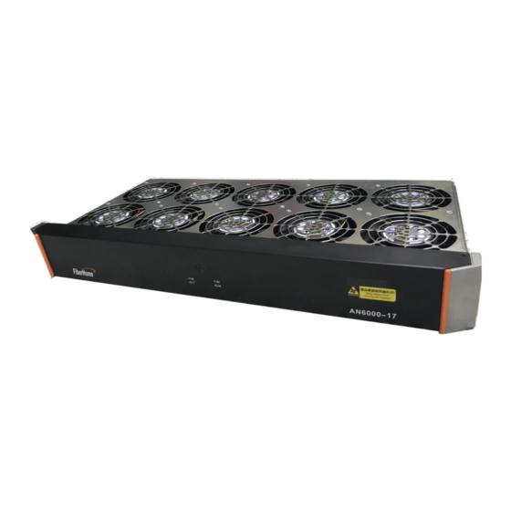
Page 14: Fan Unit
Connects with the subrack earth ground Subrack earth ground point cable. Note: The AN6000-17 is not designed with an anti-dust screen. The cabinet is used for dust prevention. Fan Unit Model The model number of the fan unit for the AN6000-17 is 405000320. - Page 15 2 Subrack exhausted from the upper part of the subrack. The fan unit is configured with a fan monitoring board, which can detect the working status of the fans. The monitoring board provides interfaces for communication with the core switch card of the equipment, and sends the monitoring information to the core switch card regularly.
-
Page 16: Slot Distribution And Cards Supported
7) Slot Distribution and Cards Supported Slot Distribution The AN6000-17 subrack has 22 vertical slots and one horizontal slot. Card Supported The slots can be classified as follows according to the cards they house:... -
Page 17: Cards
Cards Card Structure Card Overview Core Switch Card Uplink Card Power Card 10G EPON Service Card GPON / XG-PON Service Card Other Cards Version: A... -
Page 18: Card Structure
AN6000-17 Optical Line Terminal Equipment Hardware Description Card Structure Card Structure The figure below illustrates the card structure, using the GX8A card as an example. Figure 3-1 Card Structure Name Function Card Name Identifies the card. Contains various indicator LEDs, such as the interface status Indicator LED indicator LED and the card operating status indicator LED. -
Page 19: Card Overview
3 Cards Width: The height of the Depth: The maximum distance between the panel and the reed is not counted. connector. Figure 3-2 Card Dimensions The table below lists the card dimensions. Card Type Dimensions (H × W × D) Card Name Core switch card HSCA... -
Page 20: Core Switch Card
AN6000-17 Optical Line Terminal Equipment Hardware Description The core switch card aggregates, switches and controls traffic flow, processes Layer-2 protocols, and manages the faults, performance and configuration of the equipment. The uplink card provides uplink ports for uplinking. The power card inducts the DC power supply for the equipment. - Page 21 3 Cards Panel Description Table 3-1 Interfaces and Buttons Meaning Description Identifier The reset button Function reserved for future use. Connects to the USB interface storage device. USB interface Out-of-band Connects to an out-of-band network management management computer. network port Local debugging Connects to the CLI network management computer.
- Page 22 AN6000-17 Optical Line Terminal Equipment Hardware Description Table 3-2 Indicator LEDs (Continued) Meaning Description Identifier Color Status The port is not connected to the upper layer device. Technical Specifications Specification Item IEEE 802.1ag, IEEE 802.3u, IEEE 802.3x, IEEE 802. 3z, IEEE 802.1D, IEEE 802.1p, IEEE 802.1Q, IEEE Network standards 802.3ae, IEEE Std 802.1s-2002, RFC 2236, RFC...
- Page 23 3 Cards Specification Item 1.25G-10km-1310nm/1490nm-eSFP (Single-channel Single-fiber Bidirectional Optical Module) 1.25G-10km-1490nm/1310nm-eSFP (Single-channel Single-fiber Bidirectional Optical Module) 1.25G-40km-1310nm/1490nm-eSFP (Single-channel Single-fiber Bidirectional Optical Module) 1.25G-40km-1490nm/1310nm-eSFP (Single-channel Single-fiber Bidirectional Optical Module) 1.25G-80km-1570nm/1490nm-eSFP (Single-channel Single-fiber Bidirectional Optical Module) 1.25G-80km-1490nm/1570nm-eSFP (Single-channel Single-fiber Bidirectional Optical Module) GE electrical 1000M-100m-SFP (1000Base-T) module...
- Page 24 AN6000-17 Optical Line Terminal Equipment Hardware Description Function The HSCA card supports the following functions: Classification Function Provides the local commissioning serial port to meet the demand of CLI local management. Interface function Provides the out-of-band management network port to access the out-of-band network management system.
-
Page 25: Uplink Card
3 Cards Classification Function Supports suppression of broadcast packets, multicast packets and unknown packets to prevent broadcast storms in the network. Prevents DoS attacks. Working Principle Figure 3-3 Working Principle of the HSCA Card The control module is used for configuring the entire system, collecting and reporting statuses, processing protocols, and providing the USB interface, local commissioning serial port, monitoring serial port and out-of-band management network port. - Page 26 AN6000-17 Optical Line Terminal Equipment Hardware Description Panel Description Table 3-3 Interfaces Meaning Description Identifier 100G uplink optical port Connects to the IP network. 10GE uplink optical port 2 to 5 Connects to the IP network. Table 3-4 Indicator LEDs...
- Page 27 3 Cards Specification Item 1.25G-40km-1310nm-eSFP (Single-channel Two-fiber Bidirectional Optical Module) 1.25G-40km-1550nm-eSFP (Single-channel Two-fiber Bidirectional Optical Module) 1.25G-80km-1550nm-eSFP (Single-channel Two-fiber Bidirectional Optical Module) 1.25G-10km-1310nm/1490nm-eSFP (Single-channel Single-fiber Bidirectional Optical Module) 1.25G-10km-1490nm/1310nm-eSFP (Single-channel Single-fiber Bidirectional Optical Module) 1.25G-40km-1310nm/1490nm-eSFP (Single-channel Single-fiber Bidirectional Optical Module) 1.25G-40km-1490nm/1310nm-eSFP (Single-channel Single-fiber Bidirectional Optical Module) 1.25G-80km-1570nm/1490nm-eSFP (Single-channel Single-fiber...
- Page 28 AN6000-17 Optical Line Terminal Equipment Hardware Description Specification Item 10G-40km-1270nm/1330nm-SFP+ (Single-channel Single-fiber Bidirectional Optical Module) 100G optical 100G-10km-OLT-CFP4 (100G Ethernet) module Note 1: Module, 10GE Optical Module 100G Optical Module describe the module specifications. Function Provides the uplink ports. Each uplink port can be used as the network management port to connect with a network management computer.
-
Page 29: Hu8A
3 Cards 3.4.2 HU8A Basic Information Card Overview describes the number and power consumption of the card. Panel Description Table 3-5 Interfaces Meaning Description Identifier 10GE uplink optical port 1 to 8 Connects to the IP network. Table 3-6 Indicator LEDs Meaning Description Identifier... - Page 30 AN6000-17 Optical Line Terminal Equipment Hardware Description Matching Module Specification Item 1.25G-0.5km-850nm-eSFP (Single-channel Two-fiber Bidirectional Optical Module) 1.25G-10km-1310nm-eSFP (Single-channel Two-fiber Bidirectional Optical Module) 1.25G-40km-1310nm-eSFP (Single-channel Two-fiber Bidirectional Optical Module) 1.25G-40km-1550nm-eSFP (Single-channel Two-fiber Bidirectional Optical Module) 1.25G-80km-1550nm-eSFP (Single-channel Two-fiber Bidirectional Optical Module) 1.25G-10km-1310nm/1490nm-eSFP (Single-channel Single-fiber...
- Page 31 3 Cards Specification Item 10G-10km-1270nm/1330nm-SFP+ (Single-channel Single-fiber Bidirectional Optical Module) 10G-10km-1330nm/1270nm-SFP+ (Single-channel Single-fiber Bidirectional Optical Module) 10G-40km-1330nm/1270nm-SFP+ (Single-channel Single-fiber Bidirectional Optical Module) 10G-40km-1270nm/1330nm-SFP+ (Single-channel Single-fiber Bidirectional Optical Module) Note 1: GE Module 10GE Optical Module describe the module specifications. Function Provides the uplink ports.
-
Page 32: Power Card
AN6000-17 Optical Line Terminal Equipment Hardware Description The clock module provides the working clock signal for each functional module of the card. Power Card The power card inducts the DC power supply for the equipment. 3.5.1 PIBA Basic Information Card Overview describes the number and power consumption of the card. -
Page 33: 10G Epon Service Card
3 Cards Function The PIBA card provides the -48 V DC power supply for the equipment, and performs the lightning protection and power filtering functions. Working Principle The PIBA card inducts the -48 V DC power from the PDP and supplies power to the equipment. - Page 34 AN6000-17 Optical Line Terminal Equipment Hardware Description Table 3-10 Indicator LEDs (Continued) Meaning Description Identifier Color Status The card is receiving a configuration command from the Blinking core switch card or the quickly communication between the active and standby cards is being set up.
- Page 35 3 Cards Matching Module Module Type Module Code 10/1.25G-20km-10G EPON OLT asymmetric-XFP (10G/1G BASE- 10G EPON optical PRX30) module 10/1.25G-20km-10G EPON OLT symmetric-XFP (10G BASE-PR30) Note 1: 10G EPON Optical Module describes the module specifications. Function The EX8A card supports the following functions: Classification Function Interface function...
-
Page 36: Gpon / Xg-Pon Service Card
AN6000-17 Optical Line Terminal Equipment Hardware Description Working Principle Figure 3-7 Working Principle of the EX8A Card The interface module provides 10G EPON ports, and enables the conversion between EPON packets and Ethernet packets. The switch module aggregates signals from eight ports. - Page 37 3 Cards Table 3-11 Interfaces Meaning Description Identifier XG-PON port 1 to 8 Connects to a remote ONU via the ODN. Table 3-12 Indicator LEDs Meaning Description Identifier Color Status The card is working normally. Blinking slowly The card is being initialized. The card is receiving a configuration command or the Working indicator...
- Page 38 AN6000-17 Optical Line Terminal Equipment Hardware Description Matching Module Module Type Module Code XG-PON optical module 10/2.5G-20km-XG-PON OLT-SFP+ (N1 ODN CLASS) Note 1: XG-PON Optical Module describes the module specifications. Function Classification Function Provides XG-PON service ports. Interface function Supports Triple Play, including data, voice and IPTV.
-
Page 39: Gm8A
3 Cards The switch module aggregates signals from eight ports. The control module loads the card software, controls the card operation, and manages the card. The power module supplies power to each functional module of the card. The clock module provides the working clock signal for each functional module of the card. - Page 40 AN6000-17 Optical Line Terminal Equipment Hardware Description Table 3-14 Indicator LEDs (Continued) Meaning Description Identifier Color Status The port is connected to an ONU at the far end, and the ONU has been authorized. Port status LINK1-8 Green indicator LED...
- Page 41 3 Cards Classification Function Supports local and remote loopback tests. Supports remote upgrade of the card software. Supports automatic discovery and detection of ONUs. Maintenance and Supports pre-authorization and pre-configuration of ONUs. management function Supports ONU configuration in a batch manner. Supports automatic upgrade of the ONU software to facilitate maintenance and management.
-
Page 42: Gpoa
AN6000-17 Optical Line Terminal Equipment Hardware Description 3.7.3 GPOA Basic Information Card Overview describes the number and power consumption of the card. Panel Description Table 3-15 Interfaces Meaning Description Identifier GPON optical port 1 to 16 Connects to a remote ONU via the ODN. - Page 43 3 Cards Specification Item Bandwidth allocation granularity 64 kbit/s Optical fiber connector SC/PC Matching Module Module Type Module Code 2.5/1.25G-20km-GPON OLT-SFP (CLASS B+) GPON optical module 2.5/1.25G-20km-GPON OLT-SFP (CLASS C+) 2.5/1.25G-20km-GPON OLT-SFP (CLASS C++) Note 1: GPON Optical Module describes the module specifications. Function Classification Function...
-
Page 44: Other Cards
AN6000-17 Optical Line Terminal Equipment Hardware Description Working Principle Figure 3-10 Working Principle of the GPOA Card The interface module provides GPON optical ports, and enables the conversion between GPON packets and Ethernet packets. The switch module aggregates signals from 16 ports. - Page 45 3 Cards Panel Description Table 3-17 Interfaces Identifier Meaning Description Clock input interface Provides GPS clock input. CLK-IN 1PPS+TOD input Inducts the high-precision clock and time 1PPS/TOD-IN interface information from GPS. Connects to the time input port of the cascade 1PPS/TOD- 1PPS+TOD output equipment for time synchronization.
- Page 46 AN6000-17 Optical Line Terminal Equipment Hardware Description Provides the dry contact interface for 7 lines. Working Principle The conversion module transmits data transparently, and provides the dry contact interface, external clock interface, out-of-band management network port and alarm interface. The control module loads the card software, controls the card operation, and manages the card.
-
Page 47: Modules
Modules Mappings Between Modules and Cards PON Module Ethernet Module Version: A... -
Page 48: Mappings Between Modules And Cards
AN6000-17 Optical Line Terminal Equipment Hardware Description Mappings Between Modules and Cards The AN6000-17 supports encapsulation formats including SFP+, XFP, CFP4, eSFP, CSFP and SFP for pluggable modules. The module interface types include LC, SC and RJ-45 (the electrical module). - Page 49 4 Modules Module Type Application Code Card Supported Module Code 1.25G-0.5km-850nm-eSFP (Single-channel Two-fiber Bidirectional Optical Module) 1.25G-10km-1310nm-eSFP (Single-channel Two-fiber Bidirectional Optical Module) 1.25G-40km-1310nm-eSFP Single-channel two-fiber (Single-channel Two-fiber KU1A , HU8A, HSCA bidirectional optical module Bidirectional Optical Module) 1.25G-40km-1550nm-eSFP (Single-channel Two-fiber Bidirectional Optical Module) 1.25G-80km-1550nm-eSFP (Single-channel Two-fiber...
-
Page 50: Pon Module
AN6000-17 Optical Line Terminal Equipment Hardware Description Module Type Application Code Card Supported Module Code 10G-10km-1310nm-SFP+ (Single-channel Two-fiber Bidirectional Optical Module) 10G-40km-1550nm-SFP+ (Single-channel Two-fiber Bidirectional Optical Module) 10G-80km-1550nm-SFP+ (Single-channel Two-fiber Bidirectional Optical Module) 10G-20km-1270nm/1330nm-SFP + (Single-channel Single-fiber Bidirectional Optical Module) -
Page 51: 10G Epon Optical Module
4 Modules 4.2.1 10G EPON Optical Module Specification Item 10/1.25G-20km-10G EPON OLT 10/1.25G-20km-10G EPON OLT symmetric- Module code asymmetric-XFP (10G/1G BASE-PRX30) XFP (10G BASE-PR30) Optical module type 10/1G BASE-PRX30 10G BASE-PR30 Tx: 1490 nm (1480 nm to 1500 nm), 1577 Tx: 1490 nm (1480 nm to 1500 nm), 1577 nm (1575 nm to 1580 nm) Wavelength range... -
Page 52: Xg-Pon Optical Module
AN6000-17 Optical Line Terminal Equipment Hardware Description Specification Item 2.5 dBm to 5 dBm (room 4 dBm to 7 dBm (room 5.5 dBm to 10 dBm (room Output optical power temperature) temperature) temperature) Optical fiber connector SC/PC SC/PC SC/PC type... -
Page 53: Ethernet Module
4 Modules Specification Item Tx: 1490 nm (1480 nm to 1500 Tx: 1490 nm (1480 nm to 1500 GPON GPON Rx: 1310 nm (1290 nm to 1330 Rx: 1310 nm (1290 nm to 1330 Wavelength range Tx: 1577 nm (1575 nm to 1580 Tx: 1577 nm (1575 nm to 1580 XG-PON XG-PON... -
Page 54: Ge Module
AN6000-17 Optical Line Terminal Equipment Hardware Description 4.3.1 GE Module GE Optical Module Single-channel Two-fiber Bidirectional Specification Item 1.25G-80km- 1.25G-0.5km- 1.25G-10km- 1.25G-40km- 1.25G-40km- 1550nm-eSFP 850nm-eSFP 1310nm-eSFP 1310nm-eSFP 1550nm-eSFP (Single- (Single-channel (Single-channel (Single-channel (Single-channel channel Two- Module code Two-fiber Two-fiber Two-fiber... - Page 55 4 Modules GE Optical Module Single-channel Single-fiber Bidirectional Specification Item 1.25G- 1.25G-10km- 1.25G-10km- 1.25G-40km- 1.25G-40km- 1.25G-80km- 80km- 1310nm/1490- 1490nm/1310- 1310nm/1490- 1490n- 1570n- 1490n- nm-eSFP nm-eSFP nm-eSFP m/1310nm- m/1490nm- m/1570nm- (Single- (Single- (Single- eSFP (Single- eSFP (Single- eSFP channel channel channel channel channel (Single-...
-
Page 56: 10Ge Optical Module
AN6000-17 Optical Line Terminal Equipment Hardware Description GE Electrical Module Specification Item 1000M-100m-SFP (1000Base-T) Module code Module type 1000Base-T Encapsulation mode 1000 Mbit/s (full duplex) Rate Connector type RJ-45 electrical port Transmission distance 100 m 4.3.2 10GE Optical Module 10GE Optical Module... - Page 57 4 Modules Specification Item Overload -1 dBm 0.5 dBm 0.5 dBm -7 dBm optical power Extinction ratio 3 dB 3.5 dB 3.5 dB 9 dB 10GE Optical Module Single-channel Single-fiber Bidirectional Specification Item 10G-20km- 10G-20km- 10G-10km- 10G-10km- 10G-40km- 10G-40km- 1270nm/1330- 1330n- 1270n- 1330n-...
-
Page 58: 100G Optical Module
AN6000-17 Optical Line Terminal Equipment Hardware Description 4.3.3 100G Optical Module Specification Item 100G-10km-OLT-CFP4 (100G Ethernet) Module code Optical module type 100G Ethernet Wavelength range 1294.53 nm to 1310.19 nm Encapsulation mode CFP4 Rate 100 Gbit/s Output optical power 10.5 dBm... -
Page 59: Wires And Cables
Wires and Cables Cable Overview Power Cable Protection Earth Ground Cable Alarm Cable Fiber Jumper Network Cable Time Synchronization Cable Coaxial Clock Cable Serial Port Line Dry Contact Cable Version: A... -
Page 60: Cable Overview
AN6000-17 Optical Line Terminal Equipment Hardware Description Cable Overview Applied to Cable Model -48 V power cable: 3696097 (16 mm / 408000003 (25 mm 0 V power cable: 408000033 (16 ) / 408000006 (25 mm PDP850A (3000064) External Power Cable... -
Page 61: External Power Cable
5 Wires and Cables 5.2.1 External Power Cable Function The external power cables, including the -48 V power cable, 0 V power cable, and protection earth ground cable, are used to induct the power source in the equipment room to the PDP inside the cabinet. Model Table 5-1 describes the model numbers of the external power cables. - Page 62 AN6000-17 Optical Line Terminal Equipment Hardware Description Connection One end of the external power cable is connected with the PDP or the earth ground point on the top of the cabinet, and the other end is connected with the head of row cabinet.
-
Page 63: Subrack Dc Power Cable
17 to induct a set of redundant branch power rails (two branch power rails in total) from the PDP to the subrack. Model The model numbers of the DC power cables for the AN6000-17 subrack are 408000363 (-48 V power cable) and 408000364 (0 V power cable). Structure As shown in Figure 5-1, the -48 V power cable (408000363) has a cord end terminal on one end and a ring terminal on the other end. -
Page 64: Protection Earth Ground Cable
AN6000-17 Optical Line Terminal Equipment Hardware Description (1) M6 ring terminal (2) Heat-shrinkable tube (3) Power cable, black (4) Cord end terminal, ivory Figure 5-2 0 V Power Cable Connection Cable Model Cable Connector Connection Description Connected to the -48 V output... -
Page 65: Pdp Protection Earth Ground Cable
5 Wires and Cables 5.3.1 PDP Protection Earth Ground Cable Function The PDP protection earth ground cable is used to connect the PDP protection earth ground and the cabinet earth ground point. Model Table 5-3 describes the mapping between the PDP and the protection earth ground cable. -
Page 66: Subrack Protection Earth Ground Cable
Model The model number of the subrack protection earth ground cable for the AN6000-17 is 3696084. Structure The subrack protection earth ground cable is shown in Figure 5-3. Both ends of the cable are M6 pre-insulation terminals, and between them is a yellow- / green cable. -
Page 67: Alarm Cable
5 Wires and Cables Connection Cable Connector Connection Description M6 pre-insulation ring terminal Connected to the cabinet earth ground point. M6 pre-insulation ring terminal Connected to the subrack earth ground point. Technical Specifications Item Specification Single-sheathed heat-resistant (withstanding a temperature Cable type up to 90 ) single-core soft cable Yellow- / green... -
Page 68: Subrack Alarm Cable
AN6000-17 Optical Line Terminal Equipment Hardware Description Structure As shown in Figure 5-4, one end of the alarm cable for the head of row cabinet is a three-conductor D-type connector, and the other end is the three-conductor cable led out from the connector. The brown, black and blue wires output CALL (order wire call), NUA (non-urgent alarm) and UA (urgent alarm) signals respectively. - Page 69 5 Wires and Cables Structure The subrack alarm cable is a straight-through network cable with RJ-45 connectors (also known as crystal heads) on both ends, as shown in Figure 5-5. Figure 5-5 Subrack Alarm Cable Connection Connection Description Cable Connector Connected to the alarm interface (ALM) on the RJ-45 connector at the subrack side CIOA card.
-
Page 70: Fiber Jumper
AN6000-17 Optical Line Terminal Equipment Hardware Description Fiber Jumper Function Serving as the transmission carrier for optical signals, the fiber jumper is applied to short-distance transmission of optical signals. It connects the optical interface of a card to the ODF. -
Page 71: Network Cable
5 Wires and Cables Table 5-4 Connection of the Optical Fiber Jumper (Continued) Card Interface Cable Connector Connection on the ODF Side Connected Connected SFP+ (1 to 4) HSCA Connected to the IP network to provide the GE, LC/PC 1, 2 to 5 KU1A 10 GE and 100 GE optical channels. - Page 72 AN6000-17 Optical Line Terminal Equipment Hardware Description Figure 5-6 Network Cable Table 5-5 lists the pin definitions for the straight-through network cable. Table 5-5 Pin Definitions for the Straight-through Network Cable Pin of the Local End Wire Color Pin of the Opposite End...
-
Page 73: Time Synchronization Cable
5 Wires and Cables Cable Card Interface Connection at the Opposite End Cable Connector Connected Connected Connected to the network management CIOA equipment. Technical Specifications Item Specification Cable type CAT-5 twisted pair Connector type RJ-45 Number of wires Conductor diameter AWG24 Breakdown voltage 2000 V... -
Page 74: Coaxial Clock Cable
AN6000-17 Optical Line Terminal Equipment Hardware Description Table 5-6 Pin Definitions for the Time Synchronization Cable Signal Definition Meaning Not connected (high impedance) by default Not connected (high impedance) by default 422_1_N 1PPS RS-422 level GND RS-422 level GND 422_1_P... -
Page 75: Serial Port Line
5 Wires and Cables Figure 5-8 Coaxial Clock Cable Connection Connection Description Cable Cable Connector SAA series L-type Connected to the CLK-IN interface of the CIOA Coaxial clock coaxial plug card. cable Bare wire end Connected to the external clock device. Technical Specifications Table 5-7 Technical Specifications of the Coaxial Clock Cable... - Page 76 AN6000-17 Optical Line Terminal Equipment Hardware Description Model The model number of the serial port line is 3695341. Structure Table 5-8 lists the terminal definitions for the serial port line. Table 5-8 Terminal Definitions for the Serial Port Line Connected Signal...
-
Page 77: Dry Contact Cable
5 Wires and Cables 5.10 Dry Contact Cable Function The dry contact cable is used to connect the dry contact interface on the subrack or card to an external dry contact device to enable infrared detection and monitoring of smoke, mains supply, humidity, temperature, fans, shake, door access control, etc. Model The model number of the dry contact cable is 3695452. -
Page 78: Cabinet
Cabinet The following introduces the cabinets used by the AN6000-17. Cabinet Overview Detailed Dimensions of the Cabinet Equipment Layout Version: A... -
Page 79: Cabinet Overview
6 Cabinet Cabinet Overview Table 6-1 Models and Appearances of the Cabinets Cabinet Model 404000068 to 404000071 404000596 to 404000599 4102581 to 4102584 21-inch 300mm-deep cabinet 21-inch 340mm-deep cabinet 21-inch 600 mm-deep cabinet Description with anti-dust screen with anti-dust screen with anti-dust screen Appearance Among the SC/PC optical fiber connectors, the 55 mm long and 39 mm long ones are most... -
Page 80: Detailed Dimensions Of The Cabinet
2200 × 600 × 600 anti-dust screen 4102581 2600 × 600 × 600 Note 1: The AN6000-17 uses the 404000070 cabinet by default. In some special cases, cabinets of other heights can be used. Detailed Dimensions of the Cabinet Figure 6-1... -
Page 81: Equipment Layout
6 Cabinet Equipment Layout Guide When multiple AN6000-17 subracks are to be installed in a cabinet, arrange them from the top down. 21-inch Cabinet Note 1: Unit: mm Version: A... -
Page 82: Pdp
PDP Overview PDP850A (3000064) Version: A... -
Page 83: Pdp Overview
7 PDP PDP Overview The table below describes the model number, appearance and input / output specifications of the PDP for the AN6000-17. Table 7-1 Appearance and Input / Output Specifications of the PDP Item PDP850A Model 3000064-2FH Appearance Range of input voltage... - Page 84 AN6000-17 Optical Line Terminal Equipment Hardware Description SW2-1 to SW2-4 switch on / off branch power rails -48V_B_1 to -48V_B_4 respectively. Terminal Board (1) External power -48V input (2) Alarm terminal for the (3) Alarm connector for connector A head of row cabinet...
- Page 85 7 PDP Connector Type Description Connector (12) XS6, XS10 Outputs 2×4 channels of -48V power. Branch A and Branch B can back up Branch power (15) XS7, XS11 each other. rail output (2 × 4 (13) Outputs 2×4 channels of 0V power. XS8, XS9 channels) Branch A and Branch B can back up...
- Page 86 AN6000-17 Optical Line Terminal Equipment Hardware Description Short pin1 and pin2 of JP1, and the green indicator LED on the top of the cabinet will indicate the normal working status of the PDP. Short pin2 and pin3 of JP1, and the green indicator LED on the top of the cabinet will be controlled by the order wire call (CALL) signal, instead of indicating the working status of the PDP.
- Page 87 Product Documentation Customer Satisfaction Survey Thank you for reading and using the product documentation provided by FiberHome. Please take a moment to complete this survey. Your answers will help us to improve the documentation and better suit your needs. Your responses will be confidential and given serious consideration.
- Page 88 12. Additional comments about our documentation or suggestions on how we can improve: Thank you for your assistance. Please fax or send the completed survey to us at the contact information included in the documentation. If you have any questions or concerns about this survey please email at edit@fiberhome.com...
Need help?
Do you have a question about the AN6000-17 and is the answer not in the manual?
Questions and answers