Advertisement
Table of Contents
- 1 Table of Contents
- 2 Precautions
- 3 Introduction
- 4 The Features of CI-2001A/B
- 5 Technical Specification
- 6 Dimensions
- 7 Front Panel(CI-2001A)
- 8 Front Panel(CI-2001B)
- 9 Rear Panel
- 10 Installation
- 11 Test Mode
- 12 Calibration Mode
- 13 Set Mode
- 14 Serial Interface
- 15 Error Message and Trouble Shooting
- Download this manual
Advertisement
Table of Contents

Subscribe to Our Youtube Channel
Related Manuals for CAS CI-2001A


Summary of Contents for CAS CI-2001A
- Page 1 CI-2001A/B Weighing Indicator OWNER’S MANUAL...
-
Page 2: Table Of Contents
CONTENTS PRECAUTIONS INTRODUCTION THE FEATURES OF CI-2001A/B TECHNICAL SPECIFICATION DIMENSIONS FRONT PANEL(CI-2001A) FRONT PANEL(CI-2001B) REAR PANEL INSTALLATION TEST MODE CALIBRATION MODE SET MODE SERIAL INTERFACE ERROR MESSAGE AND TROUBLE SHOOTING... -
Page 3: Precautions
PRECAUTIONS Place the indicator on a flat and stable Do not use inflammable materials in surface. cleaning. Keep the main body from rain and Do not severely press because the light keep in dry area. pressing of keys can incite the operation. - Page 4 Do not subject the scale to sudden temperature changes. Keep the scale away from strong EMI noises may cause incorrect weight readings.
-
Page 5: Introduction
Also, it is programmed for the user's convenience and contains help display functions that are easily accessible. Before using CI-2001A/B, It is recommended that you read this manual carefully so you may use this device to its full potential. -
Page 6: Technical Specification
5,000 dd (NTEP, OIML) A/D external resolution 30,000 dd (Non NTEP, OIML) A/D conversion speed 10 times/sec Digital Part Full Digital Calibration: SPAC Span calibration (Single pass automatic span calibration) CI-2001A LED(6 digit) Display CI-2001B LCD(5 digit) CI-2001A 14mm(Height) Size of letter CI-2001B... -
Page 7: Dimensions
Option Part Standard Serial Interface: RS-232 Option-1 Serial Interface: RS-422/485 Option-2 Panel Mount Bracket Option-3 Inner Clock (only CI-2001B) DIMENSIONS 1. CI-2001A/B Wall Mount Type STABLE ZERO CAPACITY CI-2001B GROSS ZERO TARE PRINT LIGHT 2. CI-2001A/B(P) Panel Mount Type Cutting Size: 166mm 76mm... -
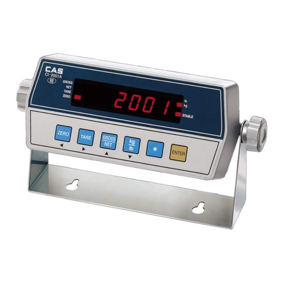
Page 8: Front Panel(Ci-2001A)
FRONT PANEL(CI-2001A) CAPACITY ZERO TARE GROSS STABLE CI-2001A GROSS ZERO TARE PRINT ENTER 1. Display lamp( ) lb lamp: ON when the weight unit is pound [lb] kg lamp: ON when the weight unit is kilogram [kg] STABLE lamp: ON when the weight is stable. - Page 9 TARE Use container in weighing. Current weight is memorized as tare weight. If you press TARE key in unload condition, Tare setting is released automatically. GROSS/NET Use this key to switch from gross to net weight. GROSS lamp on - gross weight NET lamp on - net weight In case tare weight is REGISTERED, tare and item's total weight is G.
-
Page 10: Front Panel(Ci-2001B)
FRONT PANEL(CI-2001B) 1. Display lamp( ) lb lamp: ON when the weight unit is pound [lb] kg lamp: ON when the weight unit is kilogram [kg] STABLE lamp: ON when the weight is stable. ZERO lamp: ON when the current weight is 0kg(0lb). NET lamp: ON when the current weight is NET weight. - Page 11 TARE Use container in weighing. Current weight is memorized as tare weight. If you press TARE key in unload condition, Tare setting is released automatically. GROSS/NET Use this key to switch from gross to net weight. GROSS lamp on - gross weight NET lamp on - net weight In case tare weight is REGISTERED, tare and item's total weight is G.
-
Page 12: Rear Panel
REAR PANEL RS-232C PORT: Serial interface port. (computer, printer) LOAD CELL: Port for connecting load cell. DC ADAPTER: Port for DC power.(DC 12V adapter are available) CAL S/W: Using in calibration starts. ON/OFF: Power ON/OFF switch. Legal seal installed Install the seal on the wire loop as shown in below figure. Cal Switch Plate Rear Cover Legal Seal... -
Page 13: Installation
INSTALLATION 1. Load Cell Connection Connect load cell connector to load cell port which is in the backside of indicator. Connecting method Ref. Each L/C manufacturer's or model's LOADCELL 1 CONNECTOR EX + SHLD wire color could be different. In that case, SIG + SIG - please note the following... -
Page 14: Test Mode
(CI-2001A/B kg only version) 2. Available Keys Increase the first place set value to 1. Move to the left by 1 place of the set value. Move into next test menu.(CI-2001A) ENTER Move into next test menu.(CI-2001B) LIGHT 3. Test Menu(TEST 1 - TEST 5) - Page 15 Key list < > CI-2001A CI-2001B Key mode Code Key mode Code ZERO ZERO TARE TARE PRINT kg/lb PRINT TEST 2 Function: LCD display test Display Description TEST 2 condition. Displaying all lamps of key TEST 2 is performed automatically after 3 seconds or so.
- Page 16 TEST 4 Function: RS-232 test with computer Display Description ZERO: Transmit '1' TEST 4 condition. TARE : Transmit '2' Wait for transmission and reception. G/N : Transmit '3' kg/lb : Transmit '4' Received: 1, Transmitted: none : Transmit '5' LIGHT( ): Next Received: 1, Transmitted: 13 menu REF 1.
-
Page 17: Calibration Mode
Move to the left by 1 place of the set value. Initial('0') of the set value.(kg/lb version) PRINT Initial('0') of the set value.(kg only version) Move into next menu.(CI-2001A) ENTER Move into next menu.(CI-2001B) LIGHT 3. Calibration Menu(CAL 1 - CAL 5) - Page 18 REF 2. External resolution is obtained by division the min. division by the maximum capacity. Set the resolution to be within 1/30,000. CAL 3 Function: Setting Weight In Span Calibration Range 1 ~ 999,999kg/lb(CI-2001A) 1 ~ 99,999kg/lb(CI-2001B) Display Description : Increase of no.
- Page 19 CAL 4 Function: Zero calibration Display Description CAL 4 condition. Unload the tray and press LIGHT( ): converted digital ENTER/LIGHT( ) KEY Zero calibration and value move into next checking 33333 Under zero calibration menu indicator 22222 11111 Zero calibration is completed. REF 1.
-
Page 20: Set Mode
F02 Designation of serial port usage F03 Automatic zero tracking compensation F04 Digital filter F07 Weight back-up(power-on actual weight) F08 " " key usage(CI-2001A kg version) F08 "PRINT" key usage(CI-2001B kg/lb version) F09 "ENTER" key usage(CI-2001A kg version) F09 " " key usage(CI-2001B kg version) - Page 21 9 : Much vibration Select the weight back-up mode Weight back-up is off (Power on zero) Weight back-up is on (Display setting weight) " " key usage(CI-2001A kg version) Not used Total print key "PRINT" key usage(CI-2001B kg/lb version) Not used - Print key(Press "PRINT"...
- Page 22 "ENTER" key usage(CI-2001A kg version) Not used Total print key HOLD key " " key usage(CI-2001B kg version) Not used Total print key HOLD key Device ID 00 : Device ID "00" (setting when it isn't connected with system) It is used the no. of indicator when system is connected.
- Page 23 Output mode(setting how to transmit to external equipment) In case selecting No.1 of F02, this function No data output must be set up. Stream mode Transmit only in stable condition In case selecting No.0 Transmit when data is required of F02, these keys can Request signal: device ID be set up.
-
Page 24: Serial Interface
3 Receive Data GND 7 7 Signal Ground 4 Request To Send 9pin port(Male) 5 Clear To Send RS-232C port of CI-2001A/B 6 Data Set Ready 8 Carrier Detect 20 Data Terminal Ready 25pin port(Female) Serial port of Computer RXD 3... - Page 25 Data Format Data(8 byte) CR LF US(Unstable) GS(Gross) Empty UNIT ST(Stable) NT(Net) Device ID OL(Over) Device ID Transmit 1 byte device ID so that the receiver can receive data selectively which indicator send. Weight data(8 byte) 1. 13.5 kg : '0', '0', '0', '0', '1', '3', '.', '5' 2.
- Page 26 DONE = TRUE; bioscom(1, in, COM1); return 0; CP-7000 Series Printer Connection RXD 3 2 Transmit Data TXD 2 3 Receive Data GND 7 14 Signal Ground 9pin port(Male) 15pin port(Female) RS-232C COM1 port of CP-7000 series printer port CI-2001A/B...
- Page 27 IN(-) 14 Transmit Data(-) OUT(+) 6 3 Receive Data(+) 1 Ground 7 Ground RS-485 port of CI-2001A/B 4,5,6,8 wire connect. (9pin D-type male connector) 16,17,18,19 wire connect. 25pin port Serial port of computer Connecting method of RS-485 Remote Sub Display...
-
Page 28: Error Message And Trouble Shooting
ERROR MESSAGE AND TROUBLE SHOOTING 1. Error in Weighing Mode Err 02 Reason: Failure in load cell connection or error in A/D conversion part. Trouble shooting: Check the load cell connector so that you may see if the polarity of signal is reversed. Err 06 Reason: Error in printer connection Trouble shooting: Check with printer connector. - Page 29 2. Errors in Calibration Mode Err 21 Reason: The resolution is set to be exceeded the limit 1/10,000. Trouble shooting: Lower the resolution. The resolution = allowed weight/one division Modify the allowed weight in CAL 1 or modify the division in CAL 2 so that the resolution should be below 1/10,000.
- Page 30 Err 26 Reason: The load cell output is too high at ZERO calibration. Trouble shooting: Check if the platform empty. Proceed calibration again after checking in A/D TEST mode.
Need help?
Do you have a question about the CI-2001A and is the answer not in the manual?
Questions and answers