Table of Contents
Advertisement
Advertisement
Table of Contents

Subscribe to Our Youtube Channel
Related Manuals for CAS DH


Summary of Contents for CAS DH
-
Page 2: Table Of Contents
CONTENTS ..........4 Technical Parameter ......5 Installation and Connection 1. Indicator Diagram ..........5 2. Loadcell Connection ........... 6 3. Serial Communication interface and Scoreboard ..7 ......... 9 Operation Instruction 1. Serial communication ........9 2. Key Operation ............9 3. -
Page 3: Technical Parameter
Technical Parameter 1. Analog part Class of Accuracy Class III, n=3000 Input signal range -19mV ~ 19mV Conversion speed 10 times/sec Gain drift 0.03% Excitation voltage DC 5V Max. 4ea 350 Ω Loadcell Loadcell connection 2. Display part -99999 ~ 999999 Display range (decimal point is not considered) Scale division... -
Page 4: Installation And Connection
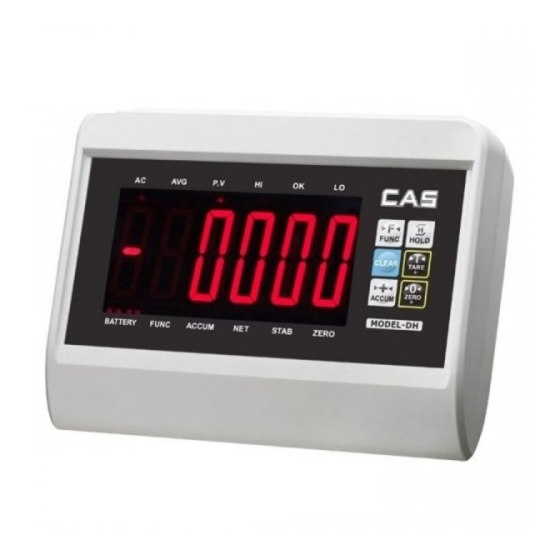
Installation and Connection 1. Indicator Diagram Front cover Back cover... -
Page 5: Loadcell Connection
Dimensions 2. Load cell Connection ■ The Load cell is connected through 9-pin plug socket (hole). Figure 2-3 shows the meaning of each pin. ■ Please use 4-core shielded cable. ▲!The connections of Loadcell and indicator must be reliable, and the shielded cable of Loadcell must be reliably grounded. -
Page 6: Serial Communication Interface And Scoreboard
1. Connection mode CAS DH communication interface uses 9-pin socket (pin). Lead pin is defined as follows: pin 2 is for TXD (serial communication data line) and pin 5 is for ground wire; shielded cable is recommended to be used as connection line. - Page 7 Method 2 P5=3 continuous transmission after stabilization. Transmitted data is weight. (gross weight, net weight or tare weight, decided by parameter P4). Gross weight format is : ww000.000kg or ww000.000lb Net weight format is : wn000.000kg or wn000.000lb Tare weight format is : wt000.000kg or wt000.000lb Note : Above decimal point position is determined by decimal point position setting of the indicator.
-
Page 8: Operation Instruction
Operation Instruction 1. Serial communication The indicator gets into self-check process after the power supply is connected. If the weight on platform is within the startup zero setting range, it will enter automatic zero, and then the weighing status. If the weight on platform exceeds the zero setting range, the indicator will give tips and display weight. - Page 9 ③ Manual accumulation of measured value: Press the [ACCUM] key when the measured value is larger or equal to 20 divisions and the data is stable in the normal weighing state, the indicator will perform "manual accumulation" function. In this case, the indicator will display the total accumulation data (in two steps): [total = ] (indicating that the content shown below is the amount of accumulation data) will show the accumulation data [******] in about 1 second.
-
Page 10: Calibration Description
Calibration Description Properly connect the signal source and power supply to preheat the indicator for 15-30 minutes when there is no load on weighing platform. After lead sealing is broken, please insert short connecting ring to connect pin J7 on the indicator main board, and allows the indicator to be calibrated. - Page 11 ③ Full capacity setting: Display 【FULL 】 press [TARE] key to come into the number input state. Display 【0 0 0 0 0 0】 press [TARE] key,indicate symbol▼will move to right one step by step to which input position you want, and press [ZERO] to add value to adjust the number you need, press [TARE] to adjust all the numbers you need until input the full capacity you need, and press [HOLD] or confirmation and indicator will come into next...
- Page 12 (2)Press [HOLD] key during startup initialization, the indicator will come into calibration state. Fast Zero calibration: Press [FUNC] key in any time before display 【nOLOAD】,the indicator will save the parameter of division, decimal point, full capacity,and come into the zero calibration state directly.
-
Page 13: User Function Setting
User’s function setting Press [FUNC] key over 5 seconds in weighing state, the indicator will come into user setting mode, there are P1~P14 fourteen parameter setting in user setting mode, press [TARE] key to adjust the number and press [ACCUM] key to come into next parameter. The parameters descriptions are as follows: 1. - Page 14 7. P7 zero tracking range x=1: 0.5e x=2: 1.0e x=3: 1.5e x=4: 2.0e x=5: 2.5e x=6: 3.0e x=7: 5.0e x=8: tracking is forbidden 8. P8 Zero range x=1: 2%FS x=2: 4%FS x=3: 10%FS x=4: 20%FS x=5: 100%FS x=6: manual Zero is forbidden 9.
- Page 15 14. P14 x Display setting x=1: brightness 1 x=2: brightness 2 x=3: brightness 3 x=4: brightness 4 x=5: brightness 5...
-
Page 16: Error Indication
Error Indication [Err 1] Inner code loading is too small or the capacity of load cell is too large [Err 2] Out of manual zero setting range [Err 3] Zero position is too high or there is heavy goods on platform when startup. [Err 7] The calibration short-circuit ring did not connected [Err 8]... - Page 17 7. Company advice for customers: start to use our indicator after test. The company is only responsible for the quality of indicator, the biggest compensation is not more than twice of indicator value, the company is not responsible failure of the whole system. 8.
- Page 18 MEMO...
Need help?
Do you have a question about the DH and is the answer not in the manual?
Questions and answers