Oriental motor BLH Series Operating Manual
Analog setting type 100 w brushless motor
Hide thumbs
Also See for BLH Series:
- User manual (148 pages) ,
- Operating manual (68 pages) ,
- Operating manual (40 pages)
Table of Contents
Advertisement
Brushless Motor
BLH Series
Analog Setting Type 100 W
OPERATING MANUAL
Thank you for purchasing an Oriental Motor product.
This Operating Manual describes product handling procedures and safety precautions.
• Please read it thoroughly to ensure safe operation.
• Always keep the manual where it is readily available.
Table of contents
1
Introduction ........................................................2
1.1
Regulations and standards ................................ 2
2
Safety precautions ............................................3
3
Precautions for use ...........................................4
4
Preparation ..........................................................5
4.1
Checking the product ......................................... 5
4.2
How to identify the product model ............... 5
4.3
Information about nameplate .......................... 5
4.4
Products possible to combine .......................... 5
4.5
Names and functions of parts .......................... 6
5
Installation ...........................................................7
5.1
Installation location.............................................. 7
5.2
Installing the driver .............................................. 7
6
Connection ..........................................................8
6.1
(CN3, CN4) .............................................................. 8
6.2
Connecting the power supply (CN1) ............. 8
6.3
Connecting the I/O signals (CN2) .................... 9
6.4
connection ...........................................................10
6.5
Grounding .............................................................11
6.6
Connection diagram ..........................................11
6.7
Noise measures ....................................................12
6.8
Conformity to the EMC Directive ..................12
7
Operation .......................................................... 14
7.1
Input signals and output signals ...................14
7.2
shaft ........................................................................17
7.3
Setting the running speed ...............................18
7.4
deceleration time...............................................19
7.5
Multi-motor control ...........................................20
8
Maintenance and inspection ..................... 21
8.1
Inspection ..............................................................21
8.2
Warranty .................................................................21
8.3
Disposal ..................................................................21
9
Troubleshooting ............................................. 22
10 Specifications ................................................... 23
10.1 Specifications .......................................................23
10.2 General specifications .......................................23
10.3 Dimension .............................................................23
HP-5098-2
Advertisement
Table of Contents

Subscribe to Our Youtube Channel
Related Manuals for Oriental motor BLH Series


Summary of Contents for Oriental motor BLH Series
-
Page 1: Table Of Contents
BLH Series Analog Setting Type 100 W OPERATING MANUAL Thank you for purchasing an Oriental Motor product. This Operating Manual describes product handling procedures and safety precautions. • Please read it thoroughly to ensure safe operation. • Always keep the manual where it is readily available. -
Page 2: Introduction
Do not use for any other purpose. For the power supply, use a DC power supply with reinforced insulation on its primary and secondary sides. Oriental Motor Co., Ltd. is not responsible for any damage caused through failure to observe this warning. -
Page 3: Safety Precautions
Safety precautions 2 Safety precautions The precautions described below are intended to ensure the safe and correct use of the product, and to prevent the user and other personnel from exposure to the risk of injury. Use the product only after carefully reading and fully understanding these instructions. -
Page 4: Precautions For Use
Do not perform gravitational operation (vertical drive). If the BLH Series is used in operation (i.e. gravitational operation) in which the motor output shaft is turned from the load side, the motor speed cannot be controlled. In addition, a gravitational load operation will cause the driver’s primary inverter voltage to exceed the allowable value, thereby triggering a protection function and causing the motor to stop spontaneously. -
Page 5: Preparation
□ Power supply cable (LH003C2) ..1 pc [300 mm (11.8 in.)] □ OPERATING MANUAL ....... 1 copy 4.2 How to identify the product model BLHD 100 K ① Driver type BLHD: BLH Series driver ② Output power 100: 100 W ① ②... -
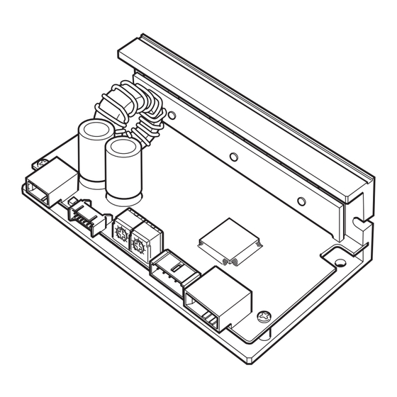
Page 6: Names And Functions Of Parts
Preparation 4.5 Names and functions of parts This section explains the name and function for each part of the driver. Power supply connector (CN1) Motor connector for power (CN4) Motor connector for signal (CN3) I/O signal connector (CN2) Internal speed potentiometer (VR1) Acceleration/deceleration time potentiometer (VR2) Name Indication... -
Page 7: Installation
Installation 5 Installation 5.1 Installation location The driver is designed and manufactured to be incorporated in equipment. Install it in a well-ventilated location that provides easy access for inspection. The location must also satisfy the following conditions: • Inside an enclosure that is installed indoors (provide vent holes) •... -
Page 8: Connection
Connection 6 Connection This chapter explains how to connect the driver with the motor, power supply cable, and I/O signals. 6.1 Connecting the motor and driver (CN3, CN4) Insert the motor cable connector into the motor connector (CN3, CN4) on the driver. When extending the motor cable, use a connection cable (sold separately). -
Page 9: Connecting The I/O Signals (Cn2)
Connection Note on power ON/OFF using a mechanical contact • When turning on or off the power supply using a mechanical contact (breaker, electromagnetic switch, relay, etc.), do so only the positive side (+) of the power supply using the mechanical contact. -
Page 10: Driver I/O Circuit And Example Connection
Connection 6.4 Driver I/O circuit and example connection „ Input signal „ The driver’s signal input is a C-MOS input. The signal status indicates “0 to 0.5 V (L level) when ON, ” or “4 to 5 V (H level) when OFF. -
Page 11: Grounding
Connection 6.5 Grounding The wire used to ground the motor and driver must be as thick and short to the grounding point as possible so that no potential difference is generated. Choose a large, thick and uniformly conductive surface for the grounding point. z Grounding the motor z Grounding the driver Connect the grounding wire along with a set screw... -
Page 12: Noise Measures
This product will conform to the EMC Directive if installed/wired using the methods specified below. „ About power supply „ The BLH Series is a product of DC power supply input. Use a DC power supply (such as a switching power supply) that optimally conforms to the EMC Directive. „ Connecting the motor cable „... - Page 13 Connection „ Ferrite core „ Use a ferrite core to suppress effect by noise propagation. Use 7427122 (Würth Elektronik GmbH & Co.KG), ZCAT3035-1330 (TDK Corporation) or equivalent ferrite cores. Install the ferrite core as close as possible to the driver. „...
-
Page 14: Operation
Operation 7 Operation 7.1 Input signals and output signals Do not perform the motor’s starting and stopping operations by turning the power supply CAUTION on and off. Perform them by inputting START/STOP and RUN/BRAKE. This may cause injury or damage to the equipment. •... - Page 15 Operation „ CW/CCW input „ CW is selected when the input is ON. CCW is selected when the input is OFF. The drive direction is the same as that of the motor output shaft when viewed from the motor output side. Depending on the gearhead ratio, the drive direction of the gear output shaft may be opposite of that of the motor.
- Page 16 Operation „ SPEED output „ Pulse signals (pulse width: 0.3 ms) of 30 pulses per revolution of the motor output shaft are output in synchronism with the motor drive. Motor speed can be calculated by measuring the SPEED output frequency. SPEED output frequency [Hz] Motor speed ∗...
-
Page 17: Rotation Direction Of The Motor Output Shaft
Operation „ Examples of operation patterns „ Two-step speed selection, Run, Instantaneous stop Direction of rotation selection deceleration stop ∗3 High speed ∗3 ∗3 ∗3 ∗2 (Clockwise direction) Low speed ∗3 ∗3 Motor operating pattern ∗2 (Counterclockwise direction) ∗3 START/ START START STOP input... -
Page 18: Setting The Running Speed
Operation 7.3 Setting the running speed Set the operating speed of the motor using the internal speed potentiometer, external speed potentiometer or external DC voltage. The motor speed range is from 100 to 3000 r/min for the case of the motor alone. Two running speeds can be set by combining the internal potentiometer and external potentiometer, or the internal potentiometer and external DC voltage. -
Page 19: Setting The Acceleration Time And Deceleration Time
Operation „ Setting by external DC voltage „ External DC voltage is used when the speed is set by D/A output from an external control device such as a programmable controller, or when the speed is switched over two levels during operation in combination with the internal speed potentiometer. -
Page 20: Multi-Motor Control
Operation 7.5 Multi-motor control If two or more motors are to be operated at the same speed, they can be controlled from the DC power supply or external potentiometer. Use external DC power supply • Use a DC power supply whose current capacity is at least the value calculated by the formula below: Current capacity when N drivers are connected: I = 1 ×... -
Page 21: Maintenance And Inspection
It is recommended that periodic inspections would be conducted for the items listed below after each operation of the motor. If an abnormal condition is noted, discontinue any use and contact your nearest Oriental Motor sales office. • Do not conduct the insulation resistance measurement or dielectric strength test with the motor and driver Note connected. -
Page 22: Troubleshooting
The motor or driver may not operate properly if the rotation speed is wrongly set or the connection is wrong. If the motor cannot operate properly, refer to the contents provided in this chapter and take appropriate action. If the problem persists, contact your nearest Oriental Motor sales office. Note Check the alarm contents when an alarm is generated. -
Page 23: Specifications
100 to 3000 r/min * For the lead wire type, “KC” of the motor model are replaced by “K”. Check on the Oriental Motor Website for the product specifications. 10.2 General specifications Ambient temperature Driver: 0 to +50 °C [+32 to +122 °F] (non-freezing) - Page 24 • Unauthorized reproduction or copying of all or part of this manual is prohibited. If a new copy is required to replace an original manual that has been damaged or lost, please contact your nearest Oriental Motor branch or sales office.
Need help?
Do you have a question about the BLH Series and is the answer not in the manual?
Questions and answers