Oriental motor BLH Series Operating Manual
Brushless motor
Hide thumbs
Also See for BLH Series:
- User manual (148 pages) ,
- Operating manual (68 pages) ,
- Operating manual (40 pages)
Table of Contents
Advertisement
Brushless Motor
BLH Series
OPERATING MANUAL
Thank you for purchasing an Oriental Motor product.
This Operating Manual describes product handling procedures and safety precautions.
• Please read it thoroughly to ensure safe operation.
• Always keep the manual where it is readily available.
Table of contents
1 Introduction ..........................................................2
2 Safety precautions ..............................................3
3 Precautions for use .............................................4
4 Preparation ............................................................5
4.1 Checking the product .............................................. 5
4.2 How to identify the product model.................... 5
4.3 Information about nameplate .............................. 5
4.4 Products possible to combine .............................. 5
4.5 Names and functions of parts .............................. 6
5 Installation .............................................................7
5.1 Installation location .................................................. 7
5.2 Installing the driver .................................................. 7
6 Connection ............................................................8
6.1 Connecting the motor and driver (CN3) ........... 8
6.2 Connecting the power supply (CN1).................. 8
6.3 Grounding ................................................................... 9
6.4 Connecting the I/O signals (CN2) ........................ 9
6.5 Driver I/O circuit .......................................................10
devices ........................................................................11
6.7 Connecting the USB cable (CN4) .......................11
6.8 Connection diagram ..............................................12
6.9 Noise measures ........................................................13
6.10 Conformity to the EMC Directive .......................13
6.11 I/O signals list ............................................................15
Digital Setting Type
7 Operation ............................................................ 16
8 Maintenance and inspection ....................... 21
9 Troubleshooting ............................................... 22
10 Alarms ................................................................... 24
11 Specifications ..................................................... 26
12 Regulations and standards ........................... 27
7.1 Guidance ....................................................................16
7.2 Setting the rotation speed ...................................16
deceleration time ....................................................17
7.4 Operation and stop ................................................18
shaft .............................................................................19
7.6 Multi-motor control ................................................20
8.1 Inspection ..................................................................21
8.2 Warranty .....................................................................21
8.3 Disposal ......................................................................21
10.1 Alarm reset ................................................................24
10.2 Alarm history ............................................................24
10.3 Alarm lists ...................................................................25
11.1 Specifications ............................................................26
11.2 General specifications ...........................................26
11.3 Dimension..................................................................26
12.1 UL Standards and CSA Standards ......................27
12.2 EU Directives .............................................................27
12.3 Republic of Korea, Radio Waves Act .................27
12.4 RoHS Directive ..........................................................27
HP-5073-2
Advertisement
Table of Contents

Related Manuals for Oriental motor BLH Series


Summary of Contents for Oriental motor BLH Series
-
Page 1: Table Of Contents
BLH Series Digital Setting Type OPERATING MANUAL Thank you for purchasing an Oriental Motor product. This Operating Manual describes product handling procedures and safety precautions. • Please read it thoroughly to ensure safe operation. • Always keep the manual where it is readily available. -
Page 2: Introduction
Do not use for any other purpose. For the power supply, use a DC power supply with reinforced insulation on its primary and secondary sides. Oriental Motor Co., Ltd. is not responsible for any damage caused through failure to observe this warning. -
Page 3: Safety Precautions
Safety precautions 2 Safety precautions The precautions described below are intended to ensure the safe and correct use of the product, and to prevent the customer and others from exposure to the risk of injury. Use the product only after carefully reading and fully understanding these instructions. -
Page 4: Precautions For Use
Do not perform gravitational operation (vertical drive). If the BLH Series is used in operation (i.e. gravitational operation) in which the motor output shaft is turned from the load side, the inverter voltage of the driver will exceed the permissible value, and the alarm function will be activated to cause the motor to coast to a stop. -
Page 5: Preparation
BLH2D 30 - K D ① ② ③ ④ ① Driver type BLH2D: BLH Series driver ② Output power 15: 15 W 30: 30 W 50: 50 W ③ Power supply voltage K: 24 VDC ④ D: Digital setting type Blank: Analog setting type 4.3 Information about nameplate... -
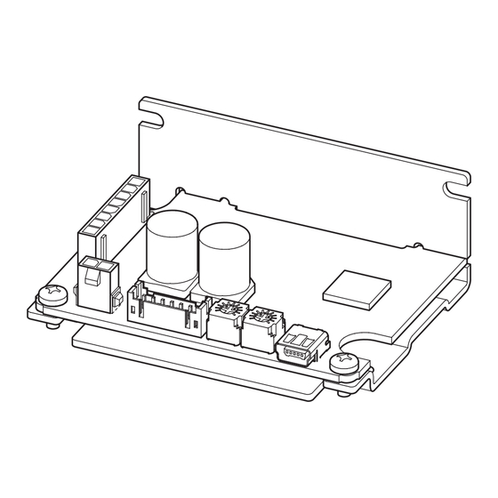
Page 6: Names And Functions Of Parts
Preparation 4.5 Names and functions of parts This section explains the name and function for each part of the driver. Motor connector (CN3) PWR/ALM Power supply connector (CN1) USB connector (CN4) LED (PWR/ALM) Internal potentiometer 1 (VR1) I/O signal connector (CN2) Internal potentiometer 2 (VR2) Name Indication... -
Page 7: Installation
Installation 5 Installation 5.1 Installation location The driver is designed and manufactured to be incorporated in equipment. Install it in a well-ventilated location that provides easy access for inspection. The location must also satisfy the following conditions: • Inside an enclosure that is installed indoors (provide vent holes) •... -
Page 8: Connection
Connection 6 Connection This chapter explains how to connect the driver with the motor, power supply cable, and I/O signals. 6.1 Connecting the motor and driver (CN3) Insert the motor cable connector into the motor connector (CN3) on the driver. When extending the motor cable, use a connection cable (sold separately). -
Page 9: Grounding
Connection 6.3 Grounding The wire used to ground the motor and driver must be as thick and short to the grounding point as possible so that no potential difference is generated. Choose a large, thick and uniformly conductive surface for the grounding point. z Grounding the motor z Grounding the driver Connect the grounding wire along with a... -
Page 10: Driver I/O Circuit
Connection 6.5 Driver I/O circuit „ Input signals circuit „ Input signals of the driver are C-MOS inputs. Driver internal circuit The signal state represents "ON: 0 to 0.5 V (L level)" +5 V and "OFF: 4 to 5 V (H level)." 10 kΩ... -
Page 11: Connecting External Analog Setting
Connection 6.6 Connecting external analog setting devices Using an external potentiometer (sold separately), external DC voltage, or PWM signal input, the rotation speed or torque limiting value can be set. „ Using an external potentiometer „ Connect to the pin No.6 to No.8 of the CN2. External potentiometer PAVR2-20K (sold separately) -
Page 12: Connection Diagram
Connection 6.8 Connection diagram The figure shows an example when an external potentiometer is connected. Driver Connecting the motor DC power supply Motor connector 24 VDC±10% – – Motor Connecting input signals Grounding DIN0 (START/STOP) Connecting the USB DIN1 (RUN/BRAKE) External potentiometer DIN2 (FWD/REV) PAVR2-20K... -
Page 13: Noise Measures
„ About power supply „ The BLH Series is a product of DC power supply input. Use a DC power supply (such as a switching power supply) that optimally conforms to the EMC Directive. „ Connecting the motor cable „... - Page 14 Connection „ Ferrite core „ Use a ferrite core to suppress effect by noise propagation. Use 7427122 (Würth Elektronik GmbH & Co.KG), ZCAT3035-1330 (TDK Corporation) or equivalent ferrite cores. Install the ferrite core as close as possible to the driver. „...
-
Page 15: I/O Signals List
Connection 6.11 I/O signals list This section explains about input signals and output signals. „ Input signals „ Terminal name Signal name Description DIN0 START/STOP This signal is used to rotate the motor or decelerate to stop it. DIN1 RUN/BRAKE This signal is used to rotate the motor or stop it instantaneously. -
Page 16: Operation
Operation 7 Operation This chapter explains how to operate the product in a state of the factory setting without using the MEXE02. 7.1 Guidance Motor Driver Setting the acceleration time and deceleration time MEXE02 Using the MEXE02, settings of the operation data and functions of the product can be extended. -
Page 17: Setting The Acceleration Time And Deceleration Time
Operation „ External DC voltage „ External DC voltage is used when the speed is set from an external External DC voltage - Rotation speed characteristics control device. (representative values) For the external DC voltage, use a DC power supply (0 to 5 VDC, 1 mA or more) with reinforced insulation on its primary and secondary sides. -
Page 18: Operation And Stop
Operation 7.4 Operation and stop To switch between operation and stop movement (instantaneous stop or deceleration stop) of the motor in the 3-wire mode, the START/STOP input and RUN/BRAKE input are used. START/STOP input RUN/BRAKE input Motor operation Operation Signal level Instantaneous stop Deceleration stop If the RUN/BRAKE input is turned OFF during deceleration stop, the motor stops instantaneously. -
Page 19: Rotation Direction Of The Motor Output
Operation 7.5 Rotation direction of the motor output shaft The rotation direction of the motor output shaft represents the direction when viewed from the motor output shaft. The motor rotation direction can be changed using the MEXE02. The figure shows when the "Motor rotation direction" parameter is set to "+=CW." REV input signal (CCW) FWD input signal... -
Page 20: Multi-Motor Control
Operation 7.6 Multi-motor control Operating two or more motors at the same speed can be performed using any of the external potentiometer, external DC voltage, or PWM signal. Using an external potentiometer Use common lines for the power supply and speed setting, and set the speed using VRx as shown in the figure below. •... -
Page 21: Maintenance And Inspection
It is recommended that periodic inspections would be conducted for the items listed below after each operation of the motor. If an abnormal condition is noted, discontinue any use and contact your nearest Oriental Motor sales office. • Do not conduct the insulation resistance measurement or dielectric strength test with the motor and driver Note connected. -
Page 22: Troubleshooting
The motor or driver may not operate properly if the rotation speed is wrongly set or the connection is wrong. If the motor cannot operate properly, refer to the contents provided in this chapter and take appropriate action. If the problem persists, contact your nearest Oriental Motor sales office. Check the alarm contents when an alarm is generated. - Page 23 Troubleshooting ● The value set in the "Torque limiting maximum value" parameter is exceeded. Torque limiting value is not ▷ Reconsider the setting value of the "Torque limiting maximum value" parameter or increased. operation data. ● If the TL input is turned OFF, the torque limiting function is disabled. Torque cannot be limited.
-
Page 24: Alarms
Alarms 10 Alarms This driver has the alarm function to protect from temperature rise, poor connection, error in operation, and others. If an alarm is generated, the ALM-A output is turned ON (in the case of normally open), or the ALM-B output is turned OFF (in the case of normally closed). -
Page 25: Alarm Lists
If the alarm is not cleared, contact your Not possible nearest Oriental Motor sales office. The data stored in the driver Initialize the parameters, and turn on the Eight times EEPROM error was damaged. -
Page 26: Specifications
2500 r/min (80 * ) 100 to 3000 r/min Speed control range * Digital setting Check on the Oriental Motor Website for the product specifications. 11.2 General specifications Ambient temperature Driver: 0 to +50 °C [+32 to +122 °F] (non-freezing) -
Page 27: Regulations And Standards
Regulations and standards 12 Regulations and standards 12.1 UL Standards and CSA Standards This product is recognized by UL under the UL and CSA standards. Applicable Standards Certification Body/Standards File No. UL 62368-1 UL/E208200 CSA C22.2 No.62368-1 12.2 EU Directives „... - Page 28 • Unauthorized reproduction or copying of all or part of this manual is prohibited. If a new copy is required to replace an original manual that has been damaged or lost, please contact your nearest Oriental Motor branch or sales office.
Need help?
Do you have a question about the BLH Series and is the answer not in the manual?
Questions and answers