
Summary of Contents for Innoflight GALAXY 950
- Page 1 Page GALAXY 950 / GALAXY 1080HL Operating Manual | Version 1.5 INNOFLIGHT INTERNATIONAL GALAXY 950 / GALAXY 1080HL MANUAL...
-
Page 2: Table Of Contents
Interface control ........................21 Connecting Landing Sensors ....................22 Battery System and MTOW ..................... 23 Galaxy 950 total payload plus battery must not exceed 10kg ..........23 Galaxy 1080HL total payload plus battery must not exceed 12kg ........23 Recommended Batteries ...................... 23 Galaxy 950/ Galaxy 1080HL .................... - Page 3 Altitude Limit ........................32 Distance Limit ........................32 Recovery Parachute DRS-10 ....................34 Automatic activation parameters ..................35 Installing the DRS-10 to the Galaxy 950 ................35 Manual activation ......................... 37 Automatic Activation Test ....................37 DRS-10 LED Status ........................ 38 | Version 1.5...
- Page 4 Additional I-GCS information ....................49 Loading Pre-existing Missions ................... 49 Read Waypoints ........................ 49 Measure Tool ........................50 Map Centring Tool ......................50 INF Flight Planner ........................50 Installation ..........................50 | Version 1.5 INNOFLIGHT INTERNATIONAL GALAXY 950 / GALAXY 1080HL MANUAL...
- Page 5 Camera Config Tab ......................55 Accepting a Survey Grid ......................55 Saving and Loading a Flight ....................55 Saving and Loading Flight Plan ..................... 55 Pre-Flight Checks ........................56 Inspections: ........................... 56 | Version 1.5 INNOFLIGHT INTERNATIONAL GALAXY 950 / GALAXY 1080HL MANUAL...
-
Page 6: Introduction
Innovative Flight Remotely Piloted Aircraft Systems (RPAS) and should be observed by all personnel. All personnel are reminded of their obligation to comply with the Federal Aviation Authority (FAA), and aeronautical information and notices published by the FAA. | Version 1.5 INNOFLIGHT INTERNATIONAL GALAXY 950 / GALAXY 1080HL MANUAL... -
Page 7: Limited Warranty
At the end of this manual is a summary of the FAA operating requirements under Part 107. The Galaxy 950 is an electric single rotor RPAS and is intended to be used for data acquisition, the Galaxy 950 should always be operated in a safe manner and in suitable environments. -
Page 8: Travel Case
5. Assembly Tool (1.5mm, 2mm, 2.5mm, 3mm Allen Key) 6. DRS-10 Parachute 7. LiDAR Scanner (Not included) 8. Landing Leg (left) 9. Galaxy 950/ 1080HL Body 10. Main Rotor Blades | Version 1.5 INNOFLIGHT INTERNATIONAL GALAXY 950 / GALAXY 1080HL MANUAL... -
Page 9: Galaxy 950 / Galaxy 1080Hl
● Height G950: 580mm (23”) ● Height G1080: 700mm (27.5”) Centre of Gravity Between 85mm (3.35”) forward of the rotor head and 40mm (1.6”) aft of the rotor head. | Version 1.5 INNOFLIGHT INTERNATIONAL GALAXY 950 / GALAXY 1080HL MANUAL... - Page 10 To check the Centre of Gravity (CG, Balance), rotate the main blades to be 90 degrees to the main body. Place your fingers on the landing gear and adjust the forward and aft to check balance location. | Version 1.5 INNOFLIGHT INTERNATIONAL GALAXY 950 / GALAXY 1080HL MANUAL...
- Page 11 Page | 11 | Version 1.5 INNOFLIGHT INTERNATIONAL GALAXY 950 / GALAXY 1080HL MANUAL...
-
Page 12: Ground Control Station
GCS powered on you will see a device named “INF GCS”, this will be paired with the headphone symbol. Select this device to pair with, once pairing is complete, restart the tablet. | Version 1.5 INNOFLIGHT INTERNATIONAL GALAXY 950 / GALAXY 1080HL MANUAL... -
Page 13: Flight Planning Software
Note: The Galaxy does not have an approved waiver to be used beyond line of sight and must be operated to FAA P107 guidelines unless the operator has received the appropriate waivers and licenses to be used outside of Part 107 regulations. | Version 1.5 INNOFLIGHT INTERNATIONAL GALAXY 950 / GALAXY 1080HL MANUAL... -
Page 14: Assembly
Page | 14 Assembly The Galaxy 950 comes prebuilt and fully tested, the system is then stored in the Galaxy 950 travel case. There are 6 main components to the Galaxy 950 assembly. Main Body Boom DRS-10 Parachute Landing leg (left) -
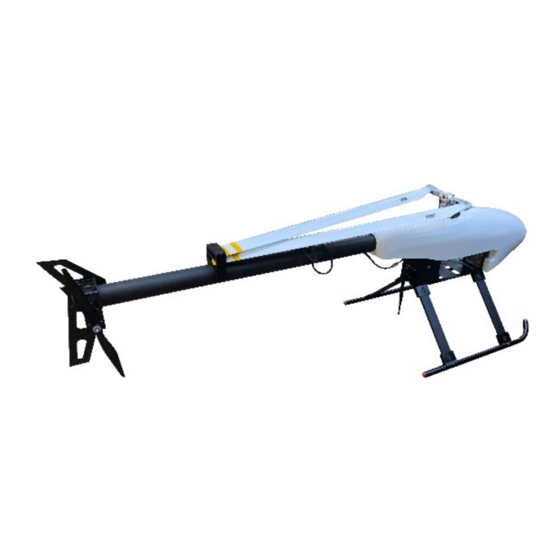
Page 15: Boom Assembly
The boom can be easily removed for transport by loosening the bolts and disconnecting the plugs, once disconnected the boom is able to slide back out of the main body. | Version 1.5 INNOFLIGHT INTERNATIONAL GALAXY 950 / GALAXY 1080HL MANUAL... - Page 16 Page | 16 | Version 1.5 INNOFLIGHT INTERNATIONAL GALAXY 950 / GALAXY 1080HL MANUAL...
-
Page 17: Canopy
The canopy is not essential for flight; it is possible to fly without the canopy. The canopy provides additional protection from the environment and makes the Galaxy more aerodynamic; however, it is an additional weight and therefore reduces the flight time slightly. | Version 1.5 INNOFLIGHT INTERNATIONAL GALAXY 950 / GALAXY 1080HL MANUAL... -
Page 18: Main Blades
If you jolt the Galaxy slightly the blades should just start to droop. If you turn the galaxy on its side and the blades fall instantly, they are too loose. | Version 1.5 INNOFLIGHT INTERNATIONAL GALAXY 950 / GALAXY 1080HL MANUAL... -
Page 19: Landing Sensors
The Landing sensors use a laser return signal to measure distance, it is critical that the clear glass face of the landing sensor is always kept clean allowing a clear return signal to be read. | Version 1.5 INNOFLIGHT INTERNATIONAL GALAXY 950 / GALAXY 1080HL MANUAL... -
Page 20: Checking The Sensors
50mm (2”) and the LED will be illuminated. This process will verify that that landing sensors are both working correctly. Shown below is the landing sensor LED in both states. | Version 1.5 INNOFLIGHT INTERNATIONAL GALAXY 950 / GALAXY 1080HL MANUAL... -
Page 21: Autopilot Led Indicator
GCS to manually disarm the Galaxy instantaneously. Please consult your distributor before attempting to fly without the landing sensors enabled. | Version 1.5 INNOFLIGHT INTERNATIONAL GALAXY 950 / GALAXY 1080HL MANUAL... -
Page 22: Connecting Landing Sensors
(left & right) to allow both landing sensors to be connected. Also located on this connector is a 2-pin auxiliary port that can be used to output a PWM signal to trigger camera shutters or control third-party sensors. | Version 1.5 INNOFLIGHT INTERNATIONAL GALAXY 950 / GALAXY 1080HL MANUAL... -
Page 23: Battery System And Mtow
XT90 plugs mounted to each side of the aircraft and connected in a series circuit to make 50 volts. The Galaxy 950 / 1080HL total payload plus battery weight must not exceed the specified weight listed below. Overloading the Galaxy payload can add additional load to the electronic and mechanical components and result in overheating. -
Page 24: Installation
Page | 24 The recommended landing voltages for the Galaxy 950/1080 are: 43.8v Consider returning home to land 43.5v Begin landing as soon as safely possible 43.0v Land immediately Never fly below 10% battery remaining Installation The Batteries are secured using a Velcro hook and loop strap that holds them to a solid carbon plate. -
Page 25: Autopilot System
AP mode switch on the GCS, press this for 2 seconds to change the flight mode from GPS lock to Attitude. This will change the flight mode from GPS lock to | Version 1.5 INNOFLIGHT INTERNATIONAL GALAXY 950 / GALAXY 1080HL MANUAL... -
Page 26: Lost Link
RTL’ page, here you can select the delay value from the time the link is lost to when RTL will activate, if activated the Galaxy will return to the take off location. | Version 1.5 INNOFLIGHT INTERNATIONAL GALAXY 950 / GALAXY 1080HL MANUAL... -
Page 27: Navigation Failsafe
The Jupiter autopilot LED status indicate the autopilot flight mode, errors or calibration modes. The lights consist of Red, Green, White and Blue. All Lights on ● No RF Link to the GCS | Version 1.5 INNOFLIGHT INTERNATIONAL GALAXY 950 / GALAXY 1080HL MANUAL... -
Page 28: Green
(dependent on AP switch) Blue ● Flashing Blue: No GPS satellites established ● Solid Blue: Compass Calibration mode Intermittent Red: Sensor Error Flashing Red: Battery low failsafe Solid Red: GPS not connected | Version 1.5 INNOFLIGHT INTERNATIONAL GALAXY 950 / GALAXY 1080HL MANUAL... -
Page 29: Green And Blue
Compass Calibration will be performed as required. It is necessary to perform compass calibration if the Galaxy has moved more than 200 miles from its last site of compass calibration, or if the magnetic declination has changed from its last calibration. | Version 1.5 INNOFLIGHT INTERNATIONAL GALAXY 950 / GALAXY 1080HL MANUAL... -
Page 30: Declination
GPS puck with the aircraft in the XY axis until the LED status changes to green and blue. • Once the LED status changes to green and blue stop rotation. | Version 1.5 INNOFLIGHT INTERNATIONAL GALAXY 950 / GALAXY 1080HL MANUAL... -
Page 31: Gps Tracking
First repeat the compass calibration process, if the crabbing is still observed adjust the declination 1 degree at a time until the flight tracking is corrected. | Version 1.5 INNOFLIGHT INTERNATIONAL GALAXY 950 / GALAXY 1080HL MANUAL... -
Page 32: Geofencing
100m (330ft) the Galaxy will slow down to a hover and not fly beyond the distance even if the command from the GCS is to keep flying. | Version 1.5 INNOFLIGHT INTERNATIONAL GALAXY 950 / GALAXY 1080HL MANUAL... - Page 33 Idle PWM value is what dictates the rotor speed, raising this value will increase the main rotor RPM. Adjustments of increments no more than “15” per adjustment is recommended. | Version 1.5 INNOFLIGHT INTERNATIONAL GALAXY 950 / GALAXY 1080HL MANUAL...
-
Page 34: Recovery Parachute Drs-10
50,000 and 67,000. Recovery Parachute DRS-10 The Galaxy 950 is equipped with a recovery parachute that is attached to the boom. The parachute is manufacture by Drone Rescue Systems for use with the Galaxy 950. The... -
Page 35: Automatic Activation Parameters
● Decent rate of more than 6m/s for longer than 0.5 seconds ● Effective from 35+ meters AGL Installing the DRS-10 to the Galaxy 950 The DRS unit is attached to the boom via two M3 bolts as shown below. | Version 1.5 INNOFLIGHT INTERNATIONAL GALAXY 950 / GALAXY 1080HL MANUAL... - Page 36 The bolts need to be tightened firmly to clamp the DRS-10 in place securely. Once the DRS-10 is bolted in place connect the 5-pin connector to supply power and signal to the system. | Version 1.5 INNOFLIGHT INTERNATIONAL GALAXY 950 / GALAXY 1080HL MANUAL...
-
Page 37: Manual Activation
Due to the Galaxy rotor head design it is only possible to test the automatic activation of the parachute by following the compass calibration procedure, physically rotating the Galaxy past 50 degrees WILL cause damage to the rotor head components. To learn more about | Version 1.5 INNOFLIGHT INTERNATIONAL GALAXY 950 / GALAXY 1080HL MANUAL... -
Page 38: Drs-10 Led Status
The DRS-10 utilises an external LED used to indicate the system status. Mechanically Arming the DRS-10 With the Galaxy 950 de-powered, use your finger to lift the white locking arm located on the outside of the DRS-10. Using the water bottle or a tube that fits inside the DRS-10 push the carbon fibre plate all the way into the DRS-10, you will feel the tension of the rubber tighten as the plate reaches the end of its travel. - Page 39 Page | 39 | Version 1.5 INNOFLIGHT INTERNATIONAL GALAXY 950 / GALAXY 1080HL MANUAL...
-
Page 40: Loading The Parachute Silk
This will hold any excess shock chord as well as stop the parachute from sliding out during flight. If the Velcro strap is not secured in place correctly | Version 1.5 INNOFLIGHT INTERNATIONAL GALAXY 950 / GALAXY 1080HL MANUAL... -
Page 41: Storing The Parachute
Store the parachute silk inside the carboard sleeve with a rubber band around to keep the package secured. | Version 1.5 INNOFLIGHT INTERNATIONAL GALAXY 950 / GALAXY 1080HL MANUAL... -
Page 42: Flight Planning
To locate “General Setup” select the symbol at the top left of the main page. This will display the INF logo with 3 options below, “General Setup”, “Parameter Setup” and “RTK Setup”. | Version 1.5 INNOFLIGHT INTERNATIONAL GALAXY 950 / GALAXY 1080HL MANUAL... -
Page 43: Telemetry Data
Telemetry Data It is required to customize the telemetry and system options to your preferences. Below is a guide based on the recommended settings for operating the Galaxy. | Version 1.5 INNOFLIGHT INTERNATIONAL GALAXY 950 / GALAXY 1080HL MANUAL... -
Page 44: Telemetry Data
“Add Info” and “Delete Info”. In the attached images to this manual you will see the recommended telemetry data to be operate the Galaxy aircraft. | Version 1.5 INNOFLIGHT INTERNATIONAL GALAXY 950 / GALAXY 1080HL MANUAL... -
Page 45: Adding Telemetry Additional Data
On the right side of I-GCS, the tools required to plan missions are set out vertically. To begin planning a mission select the “Create” Icon , this will enter the mission planning screen. | Version 1.5 INNOFLIGHT INTERNATIONAL GALAXY 950 / GALAXY 1080HL MANUAL... -
Page 46: Plotting Flight Plan Area
The outline can be altered by dragging the pins to edit the selected flight area. | Version 1.5 INNOFLIGHT INTERNATIONAL GALAXY 950 / GALAXY 1080HL MANUAL... -
Page 47: Grid Planning
1.2 seconds, this will give the camera buffer time to continue taking images. Route Angle The Route Angle value sets the angle of flight path for the entire grid. | Version 1.5 INNOFLIGHT INTERNATIONAL GALAXY 950 / GALAXY 1080HL MANUAL... -
Page 48: Route Width
Altitude Set the altitude to be flown Camera trigger distance As well as shutter time it is also possible to set the distance between images as a set distance. | Version 1.5 INNOFLIGHT INTERNATIONAL GALAXY 950 / GALAXY 1080HL MANUAL... -
Page 49: Completing Flight Planning
The waypoints can only be read if the Galaxy power has not be cycled, the Galaxy will only store the last written waypoint file. When re powered the waypoint file is cleared from the autopilot. | Version 1.5 INNOFLIGHT INTERNATIONAL GALAXY 950 / GALAXY 1080HL MANUAL... -
Page 50: Measure Tool
Opening the software is done by double clicking the ‘INF Flight Planner’ shortcut icon on the GCS desktop, or by navigating to the user installation location and double clicking the | Version 1.5 INNOFLIGHT INTERNATIONAL GALAXY 950 / GALAXY 1080HL MANUAL... -
Page 51: Flight Planning
To orient the map on a new project site the GCS operator can zoom out the map either by using the ‘Zoom’ slider on the right-hand side of the map, or by using a centre wheel of a | Version 1.5 INNOFLIGHT INTERNATIONAL GALAXY 950 / GALAXY 1080HL MANUAL... -
Page 52: Setting Home Position For Flight Planning
Entering the draw polygon by either method will allow the user to place successive red markers at desired boundary points. Each point will have a red line from the previous red marker and a red line closing the polygon. | Version 1.5 INNOFLIGHT INTERNATIONAL GALAXY 950 / GALAXY 1080HL MANUAL... -
Page 53: Importing A Shape File
● Altitude (m): Sets the flying height above the ground. It is to be noted that this is not above sea-level – unless specified set up for above sea level by manufacturer. ● Angle [deg]: Sets the direction of the flight lines. | Version 1.5 INNOFLIGHT INTERNATIONAL GALAXY 950 / GALAXY 1080HL MANUAL... -
Page 54: Display
The distance past the natural end of a flight line where an extra waypoint is placed to extend the flight line. There are two input boxes for this option. Each one is applied to only one end of the flight line. | Version 1.5 INNOFLIGHT INTERNATIONAL GALAXY 950 / GALAXY 1080HL MANUAL... -
Page 55: Lead-In
There are two buttons labelled ‘Load WP File’ and ‘Save WP File’. These open standard windows load and save sub-windows. Once opened navigate through the system to desired location and either save or load the desired file. | Version 1.5 INNOFLIGHT INTERNATIONAL GALAXY 950 / GALAXY 1080HL MANUAL... -
Page 56: Pre-Flight Checks
When the altitude slider is pushed up the entire swash plate should slide up evenly and positive pitch angle of the blades will be observed. | Version 1.5 INNOFLIGHT INTERNATIONAL GALAXY 950 / GALAXY 1080HL MANUAL... -
Page 57: Autopilot Status Check
Flight Data page. Right click in the map region and select ‘Trigger Camera Now’. A confirmation box will appear on the screen, at the same time the camera will take a photo. | Version 1.5 INNOFLIGHT INTERNATIONAL GALAXY 950 / GALAXY 1080HL MANUAL... -
Page 58: Take-Off Procedure
Galaxy pointing directly away from you, this allows you to react to control easily if needed. There should be no obstacles or people within a 30m radius of the Galaxy during take-off and landing. | Version 1.5 INNOFLIGHT INTERNATIONAL GALAXY 950 / GALAXY 1080HL MANUAL... -
Page 59: Ap Switch To On / Gps Mode
NAV Mode can be selected. The pilot should increase flying height to achieve a safe altitude to manoeuvre flight using the Cyclic/Joystick to guide the Galaxy in the desired direction. | Version 1.5 INNOFLIGHT INTERNATIONAL GALAXY 950 / GALAXY 1080HL MANUAL... -
Page 60: Navigation Mode
We recommend that the auto landing function is only ever used as an emergency procedure where a command link from | Version 1.5 INNOFLIGHT INTERNATIONAL GALAXY 950 / GALAXY 1080HL MANUAL... -
Page 61: Flight Characteristic Tuning
RPM decreases Flight Characteristic tuning The Galaxy 950/1080 autopilot is specifically tuned to each Galaxy aircraft. Every aircraft has slight individual characteristics that require varied tuning from the default values, however environmental conditions also influence the flight performance as well as different payload weights. -
Page 62: Rotor Head Gains
Lock gain. For example, a low lock gain and low I gain would result in a weak heading hold as the tail would have low sensitivity and power to heading control. | Version 1.5 INNOFLIGHT INTERNATIONAL GALAXY 950 / GALAXY 1080HL MANUAL... -
Page 63: Flight Data Logging
To download the flight data, click “Raw Data (Binary)”. A window will appear asking for a save location and file name, the file will be saved as .blog this file can then be emailed to Innoflight for analysis. | Version 1.5... -
Page 64: Georeferenced Photolog
Latitude, Longitude, Height, IMU data, Heading and GPS time stamp. To download this file select “Georeference data” and save the file. A folder with open asking for save location and the file will be saved as a .txt file. | Version 1.5 INNOFLIGHT INTERNATIONAL GALAXY 950 / GALAXY 1080HL MANUAL... -
Page 65: Autopilot Log Storage
There is no guarantee that the flight log will be salvageable in the event or water or fire damage. In the event of either of these situations it is vital to contact Innoflight immediately to remove the storage card from inside the autopilot. - Page 66 The FAA expects LAANC will ultimately provide near real-time processing of airspace authorization requests for drone operators nationwide. The system is designed to automatically approve most requests to operate in specific areas of airspace below designated altitudes. | Version 1.5 INNOFLIGHT INTERNATIONAL GALAXY 950 / GALAXY 1080HL MANUAL...
- Page 67 Page | 67 | Version 1.5 INNOFLIGHT INTERNATIONAL GALAXY 950 / GALAXY 1080HL MANUAL...