
Related Manuals for Haulotte HA26 RTJ O


Summary of Contents for Haulotte HA26 RTJ O
- Page 1 Maintenance Book MAINTENANCE BOOK HA26 RTJ O - HA26 RTJ O SW - HA26 RTJ PRO - HA26 RTJ PRO SW - HA80 RTJ O - HA80 RTJ PRO 4001055180 E 06.21 USA / GB...
- Page 2 HA26 RTJ O - HA26 RTJ O SW - HA26 RTJ PRO - HA26 RTJ PRO SW - HA80 RTJ O - HA80 RTJ PRO 24203 4001055180 0 E 06.21 USA / GB...
-
Page 3: Table Of Contents
2.3 - HAULOTTE Services®........ - Page 4 Maintenance Book 2 - List of actuators and sensors ... . . 2.1 - Sensors and actuators......... 2.2 - Sensors detail.
- Page 5 Maintenance Book Machine sheet Structural part inspection ....MS0001 - Pins and bearing inspection ... . MS0002 - Cylinder inspection .
- Page 6 Maintenance Book Replacing the engine oil filter - Kohler MP0004 - engine ........Diesel filter replacement .
- Page 7 Maintenance Book Trouble shooting and diagram 1 - Trouble shooting ..... . 1.1 - Recommendations......... . . 1.2 - Description .
- Page 8 Maintenance Book...
- Page 9 Only the specifications in this manual should be used to study the suitability of the equipment for the intended use. This maintenance and repairs book is specific to the HAULOTTE® products listed on the cover page of this manual. The maintenance book is intended for the on-site maintenance technician.
-
Page 10: Symbols And Colors
HA26 RTJ O - HA26 RTJ O SW - HA26 RTJ PRO - HA26 RTJ PRO SW - HA80 RTJ O - HA80 RTJ PRO - Preface - Foreword 1 - Symbols and colors Symbols and colors are used to alert the operator of safety precautions and/or to highlight important safety information. - Page 11 HA26 RTJ O - HA26 RTJ O SW - HA26 RTJ PRO - HA26 RTJ PRO SW - HA80 RTJ O - HA80 RTJ PRO - Preface - Foreword Decals Color Title Description Danger : Indicates a hazardous situation which if not avoided, WILL result in death or serious injury.
- Page 12 HA26 RTJ O - HA26 RTJ O SW - HA26 RTJ PRO - HA26 RTJ PRO SW - HA80 RTJ O - HA80 RTJ PRO - Preface - Foreword Notes 4001055180 E 06.21 USA / GB...
-
Page 13: Safety
HA26 RTJ O - HA26 RTJ O SW - HA26 RTJ PRO - HA26 RTJ PRO SW - HA80 RTJ O - HA80 RTJ PRO - Safety Safety 1 - General safety rules 1.1 - AINTENANCE IMPLEMENTATION Your safety and the safety of the people around are essential. -
Page 14: Uncontrolled Movement Hazard
HA26 RTJ O - HA26 RTJ O SW - HA26 RTJ PRO - HA26 RTJ PRO SW - HA80 RTJ O - HA80 RTJ PRO - Safety Note : • Using the machine during maintenance is strictly forbidden. • Do not climb onto the covers. -
Page 15: Electric Shock Hazards
HA26 RTJ O - HA26 RTJ O SW - HA26 RTJ PRO - HA26 RTJ PRO SW - HA80 RTJ O - HA80 RTJ PRO - Safety 1.3 - LECTRIC HOCK AZARDS The machine is not electrically insulated and does not provide protection from contact or proximity to electrically charged conductors. -
Page 16: Explosion / Fire Hazards
HA26 RTJ O - HA26 RTJ O SW - HA26 RTJ PRO - HA26 RTJ PRO SW - HA80 RTJ O - HA80 RTJ PRO - Safety 1.4 - XPLOSION AZARDS Always wear protective clothing and eye wear when working with batteries and power sources/systems. -
Page 17: Maintenance And Repair Training
2.3 - HAULOTTE S ® ERVICES The HAULOTTE® is at your service in all 5 continents of the world via an extensive network of its own factory trained technicians, who are ready to respond to your every need. 2.4 - RAINING Whether you want to just service your equipment or carry out a complete overhaul, HAULOTTE®... -
Page 18: Product Modification
HA26 RTJ O - HA26 RTJ O SW - HA26 RTJ PRO - HA26 RTJ PRO SW - HA80 RTJ O - HA80 RTJ PRO - Safety 2.5 - RODUCT MODIFICATION In a constant effort to improve the quality of machines, HAULOTTE continually monitors technical improvements that enable to develop products with improved safety and greater reliability. -
Page 19: Familiarization
HA26 RTJ O - HA26 RTJ O SW - HA26 RTJ PRO - HA26 RTJ PRO SW - HA80 RTJ O - HA80 RTJ PRO - Familiarization Familiarization Notes 4001055180 E 06.21 USA / GB... -
Page 20: Primary Machine Components
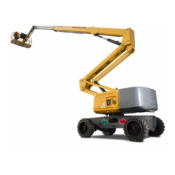
- Familiarization 1 - Primary machine components 1.1 - AYOUT HA26 RTJ O - HA26 RTJ O SW - HA26 RTJ PRO - HA26 RTJ PRO SW - HA80 RTJ O - HA80 RTJ PRO 4001055180 E 06.21 USA / GB... - Page 21 HA26 RTJ O - HA26 RTJ O SW - HA26 RTJ PRO - HA26 RTJ PRO SW - HA80 RTJ O - HA80 RTJ PRO - Familiarization Marking Description Marking Description Chassis Arm lifting cylinder Steering wheel Ground control box + Universal plug...
-
Page 22: Ground Control Box
HA26 RTJ O - HA26 RTJ O SW - HA26 RTJ PRO - HA26 RTJ PRO SW - HA80 RTJ O - HA80 RTJ PRO - Familiarization 1.2 - ROUND CONTROL BOX 1.2.1 - Layout General view 4001055180 E 06.21... - Page 23 HA26 RTJ O - HA26 RTJ O SW - HA26 RTJ PRO - HA26 RTJ PRO SW - HA80 RTJ O - HA80 RTJ PRO - Familiarization Controls and indicators Marking Name Description Function By pressing on : Tilt the platform towards the front of...
- Page 24 HA26 RTJ O - HA26 RTJ O SW - HA26 RTJ PRO - HA26 RTJ PRO SW - HA80 RTJ O - HA80 RTJ PRO - Familiarization Marking Name Description Function "Overriding system" control By pressing on : Authorize movements from the...
- Page 25 HA26 RTJ O - HA26 RTJ O SW - HA26 RTJ PRO - HA26 RTJ PRO SW - HA80 RTJ O - HA80 RTJ PRO - Familiarization Marking Name Description Function DPF regeneration SA600D By pressing on : Regeneration start-up...
-
Page 26: Haulotte Activ'screen 2
HA26 RTJ O - HA26 RTJ O SW - HA26 RTJ PRO - HA26 RTJ PRO SW - HA80 RTJ O - HA80 RTJ PRO - Familiarization 1.2.2 - HAULOTTE Activ'Screen 2 Upon starting and during operation of the machine, the LCD screen "Activ'Screen" located on the ground control box displays in real time the machine operating status. - Page 27 HA26 RTJ O - HA26 RTJ O SW - HA26 RTJ PRO - HA26 RTJ PRO SW - HA80 RTJ O - HA80 RTJ PRO - Familiarization On initial start-up of the machine or after 3 day of inactivity, the following screens are displayed in order.
- Page 28 HA26 RTJ O - HA26 RTJ O SW - HA26 RTJ PRO - HA26 RTJ PRO SW - HA80 RTJ O - HA80 RTJ PRO - Familiarization Controls and indicators Icon Description Function Icon Description Function Access code not yet entered...
- Page 29 HA26 RTJ O - HA26 RTJ O SW - HA26 RTJ PRO - HA26 RTJ PRO SW - HA80 RTJ O - HA80 RTJ PRO - Familiarization Controls and indicators Icon Description Function Icon Description Function The machine can be personalized with a user identification code.
- Page 30 HA26 RTJ O - HA26 RTJ O SW - HA26 RTJ PRO - HA26 RTJ PRO SW - HA80 RTJ O - HA80 RTJ PRO - Familiarization Controls and indicators Icon Description Function Icon Description Function Emergency mode is activated when : •...
- Page 31 HA26 RTJ O - HA26 RTJ O SW - HA26 RTJ PRO - HA26 RTJ PRO SW - HA80 RTJ O - HA80 RTJ PRO - Familiarization Controls and indicators Icon Description Function Icon Description Function Home screen (dashboard) (Will be visible - depending on the machine)
- Page 32 HA26 RTJ O - HA26 RTJ O SW - HA26 RTJ PRO - HA26 RTJ PRO SW - HA80 RTJ O - HA80 RTJ PRO - Familiarization Controls and indicators Icon Description Function Icon Description Function Home screen (dashboard) (Will be visible - depending on the machine) •...
- Page 33 HA26 RTJ O - HA26 RTJ O SW - HA26 RTJ PRO - HA26 RTJ PRO SW - HA80 RTJ O - HA80 RTJ PRO - Familiarization Controls and indicators Icon Description Function Icon Description Function Home screen (dashboard) (Will be visible - depending on the machine) •...
- Page 34 HA26 RTJ O - HA26 RTJ O SW - HA26 RTJ PRO - HA26 RTJ PRO SW - HA80 RTJ O - HA80 RTJ PRO - Familiarization Controls and indicators Icon Description Function Icon Description Function Home screen (dashboard) (Will be visible - depending on the machine) •...
- Page 35 HA26 RTJ O - HA26 RTJ O SW - HA26 RTJ PRO - HA26 RTJ PRO SW - HA80 RTJ O - HA80 RTJ PRO - Familiarization Icon Description Function Icon Description Function DPF regeneration in progress, high temperature • Light stays on during...
- Page 36 HA26 RTJ O - HA26 RTJ O SW - HA26 RTJ PRO - HA26 RTJ PRO SW - HA80 RTJ O - HA80 RTJ PRO - Familiarization Controls and indicators Icon Description Function Icon Description Function Home screen (dashboard) (Will be visible - depending on the machine) •...
- Page 37 HA26 RTJ O - HA26 RTJ O SW - HA26 RTJ PRO - HA26 RTJ PRO SW - HA80 RTJ O - HA80 RTJ PRO - Familiarization Controls and indicators Icon Description Function Icon Description Function Home screen (dashboard) (Will be visible - depending on the machine)
- Page 38 HA26 RTJ O - HA26 RTJ O SW - HA26 RTJ PRO - HA26 RTJ PRO SW - HA80 RTJ O - HA80 RTJ PRO - Familiarization Controls and indicators Icon Description Function Icon Description Function Home screen (dashboard) (Will be visible - depending on the machine) •...
- Page 39 HA26 RTJ O - HA26 RTJ O SW - HA26 RTJ PRO - HA26 RTJ PRO SW - HA80 RTJ O - HA80 RTJ PRO - Familiarization Controls and indicators Icon Description Function Icon Description Function Home screen (dashboard) (Will be visible - depending on the machine)
- Page 40 HA26 RTJ O - HA26 RTJ O SW - HA26 RTJ PRO - HA26 RTJ PRO SW - HA80 RTJ O - HA80 RTJ PRO - Familiarization Controls and indicators Icon Description Function Icon Description Function Home screen (dashboard) (Will be visible - depending on the machine) Layout Engine’s automatic preheat system is...
- Page 41 HA26 RTJ O - HA26 RTJ O SW - HA26 RTJ PRO - HA26 RTJ PRO SW - HA80 RTJ O - HA80 RTJ PRO - Familiarization Controls and indicators Icon Description Function Icon Description Function Home screen (dashboard) (Will be visible - depending on the machine) Fuel level is low.
- Page 42 HA26 RTJ O - HA26 RTJ O SW - HA26 RTJ PRO - HA26 RTJ PRO SW - HA80 RTJ O - HA80 RTJ PRO - Familiarization Controls and indicators Icon Description Function Icon Description Function Home screen (dashboard) (Will be visible - depending on the machine)
- Page 43 HA26 RTJ O - HA26 RTJ O SW - HA26 RTJ PRO - HA26 RTJ PRO SW - HA80 RTJ O - HA80 RTJ PRO - Familiarization Controls and indicators Icon Description Function Icon Description Function Home screen (dashboard) (Will be visible - depending on the machine) F12.01 bus CAN...
- Page 44 HA26 RTJ O - HA26 RTJ O SW - HA26 RTJ PRO - HA26 RTJ PRO SW - HA80 RTJ O - HA80 RTJ PRO - Familiarization Controls and indicators Icon Description Function Icon Description Function Home screen (dashboard) (Will be visible - depending on the machine) •...
- Page 45 HA26 RTJ O - HA26 RTJ O SW - HA26 RTJ PRO - HA26 RTJ PRO SW - HA80 RTJ O - HA80 RTJ PRO - Familiarization Controls and indicators Icon Description Function Icon Description Function Machine fault (Will be visible - depending on the machine) Machine fault icons Failure code F01.xx Fault - Variator...
- Page 46 HA26 RTJ O - HA26 RTJ O SW - HA26 RTJ PRO - HA26 RTJ PRO SW - HA80 RTJ O - HA80 RTJ PRO - Familiarization Controls and indicators Icon Description Function Icon Description Function Machine fault (Will be visible - depending on the machine)
- Page 47 HA26 RTJ O - HA26 RTJ O SW - HA26 RTJ PRO - HA26 RTJ PRO SW - HA80 RTJ O - HA80 RTJ PRO - Familiarization Notes 4001055180 E 06.21 USA / GB...
-
Page 48: Platform Control Box
HA26 RTJ O - HA26 RTJ O SW - HA26 RTJ PRO - HA26 RTJ PRO SW - HA80 RTJ O - HA80 RTJ PRO - Familiarization 1.3 - LATFORM CONTROL BOX 1.3.1 - Layout General view 4001055180 E 06.21... - Page 49 HA26 RTJ O - HA26 RTJ O SW - HA26 RTJ PRO - HA26 RTJ PRO SW - HA80 RTJ O - HA80 RTJ PRO - Familiarization Controls and indicators Marking Name Description Function Move forward : Forward drive Drive joystick...
- Page 50 HA26 RTJ O - HA26 RTJ O SW - HA26 RTJ PRO - HA26 RTJ PRO SW - HA80 RTJ O - HA80 RTJ PRO - Familiarization Marking Name Description Function All 4 wheels steer SA101 Front 2 wheels steer...
-
Page 51: Display Panel (Led's 101 - 117)
HA26 RTJ O - HA26 RTJ O SW - HA26 RTJ PRO - HA26 RTJ PRO SW - HA80 RTJ O - HA80 RTJ PRO - Familiarization 1.3.2 - Display Panel (LED'S 101 - 117) Upper control box display Marking... - Page 52 HA26 RTJ O - HA26 RTJ O SW - HA26 RTJ PRO - HA26 RTJ PRO SW - HA80 RTJ O - HA80 RTJ PRO - Familiarization Marking Name Symbol Function LED 113 HL804 Radius limit LED 114 HL802 Overload LED 115 Turret at 180°...
- Page 53 HA26 RTJ O - HA26 RTJ O SW - HA26 RTJ PRO - HA26 RTJ PRO SW - HA80 RTJ O - HA80 RTJ PRO - Familiarization Symbol Description Machine switched on : • Rapid flashing : Machine is ON, but platform control box is not active but the ground control box is ON •...
- Page 54 HA26 RTJ O - HA26 RTJ O SW - HA26 RTJ PRO - HA26 RTJ PRO SW - HA80 RTJ O - HA80 RTJ PRO - Familiarization Symbol Description Platform leveling +/- 10° : • Illuminated if the angle of the platform reaches +/- 10° in relation to the horizontal and movement control...
- Page 55 HA26 RTJ O - HA26 RTJ O SW - HA26 RTJ PRO - HA26 RTJ PRO SW - HA80 RTJ O - HA80 RTJ PRO - Familiarization Notes 4001055180 E 06.21 USA / GB...
-
Page 56: List Of Actuators And Sensors
HA26 RTJ O - HA26 RTJ O SW - HA26 RTJ PRO - HA26 RTJ PRO SW - HA80 RTJ O - HA80 RTJ PRO - Familiarization 2 - List of actuators and sensors 2.1 - ENSORS AND ACTUATORS Sensors and actuators 4001055180 E 06.21... - Page 57 HA26 RTJ O - HA26 RTJ O SW - HA26 RTJ PRO - HA26 RTJ PRO SW - HA80 RTJ O - HA80 RTJ PRO - Familiarization Name Description EL906 Light - Activ' Lighting System Counterweight light EL907 Light - Activ' Lighting System Boom light...
- Page 58 HA26 RTJ O - HA26 RTJ O SW - HA26 RTJ PRO - HA26 RTJ PRO SW - HA80 RTJ O - HA80 RTJ PRO - Familiarization Name Description YV250 R Valve-Right turntable rotation YV420 PWM Arm electrovalve YV420 U...
-
Page 59: Sensors Detail
HA26 RTJ O - HA26 RTJ O SW - HA26 RTJ PRO - HA26 RTJ PRO SW - HA80 RTJ O - HA80 RTJ PRO - Familiarization 2.2 - ENSORS DETAIL 2.2.1 - Turret Marking Item Description SQ800 Tilt sensor... -
Page 60: Kubota Engine
HA26 RTJ O - HA26 RTJ O SW - HA26 RTJ PRO - HA26 RTJ PRO SW - HA80 RTJ O - HA80 RTJ PRO - Familiarization 2.2.2 - Kubota Engine Assembly Detail on pumps Marking Item Description Diesel engine EGV KUBOTA V2403 36.5 KW... -
Page 61: Diesel Engine Tier 3 V2403 36.5Kw
HA26 RTJ O - HA26 RTJ O SW - HA26 RTJ PRO - HA26 RTJ PRO SW - HA80 RTJ O - HA80 RTJ PRO - Familiarization 2.2.2.1 - Diesel engine Tier 3 V2403 36.5KW 4001055180 E 06.21 USA / GB... - Page 62 HA26 RTJ O - HA26 RTJ O SW - HA26 RTJ PRO - HA26 RTJ PRO SW - HA80 RTJ O - HA80 RTJ PRO - Familiarization Detail on EGV and relay Marking Item Description SP300 Oil pressure YA300 Engine variable speed control solenoid (including stop function)
- Page 63 HA26 RTJ O - HA26 RTJ O SW - HA26 RTJ PRO - HA26 RTJ PRO SW - HA80 RTJ O - HA80 RTJ PRO - Familiarization Detail on EDC - Kubota module 4001055180 E 06.21 USA / GB...
- Page 64 HA26 RTJ O - HA26 RTJ O SW - HA26 RTJ PRO - HA26 RTJ PRO SW - HA80 RTJ O - HA80 RTJ PRO - Familiarization Marking Item Description EDC71CV45 ECU KUBOTA module KM160 Preheating relay feed pump Main relay...
-
Page 65: Kohler Engine
HA26 RTJ O - HA26 RTJ O SW - HA26 RTJ PRO - HA26 RTJ PRO SW - HA80 RTJ O - HA80 RTJ PRO - Familiarization 2.2.3 - Kohler Engine Assembly Detail on pumps Marking Item Description Diesel engine Kohler KDI1903... -
Page 66: Diesel Engine - Kohler Stage V (Kdi 1903 Tc - 36,5 Kw - 50Hp)
HA26 RTJ O - HA26 RTJ O SW - HA26 RTJ PRO - HA26 RTJ PRO SW - HA80 RTJ O - HA80 RTJ PRO - Familiarization 2.2.3.1 - Diesel engine - Kohler STAGE V (KDI 1903 TC - 36,5 kW - 50hp) - Page 67 HA26 RTJ O - HA26 RTJ O SW - HA26 RTJ PRO - HA26 RTJ PRO SW - HA80 RTJ O - HA80 RTJ PRO - Familiarization 4001055180 E 06.21 USA / GB...
- Page 68 HA26 RTJ O - HA26 RTJ O SW - HA26 RTJ PRO - HA26 RTJ PRO SW - HA80 RTJ O - HA80 RTJ PRO - Familiarization Marking Item Description Starter motor SP160B Pressure transducer - Reverse drive SP160F Pressure transducer - Forward drive...
- Page 69 HA26 RTJ O - HA26 RTJ O SW - HA26 RTJ PRO - HA26 RTJ PRO SW - HA80 RTJ O - HA80 RTJ PRO - Familiarization Ambient air temperature sensor - ST901 EGR valve 4001055180 E 06.21 USA / GB...
- Page 70 HA26 RTJ O - HA26 RTJ O SW - HA26 RTJ PRO - HA26 RTJ PRO SW - HA80 RTJ O - HA80 RTJ PRO - Familiarization Marking Description T MAP sensor: Input pressure detection Delta P sensor: Detection of clogging level of DPF filter 4001055180 E 06.21...
- Page 71 HA26 RTJ O - HA26 RTJ O SW - HA26 RTJ PRO - HA26 RTJ PRO SW - HA80 RTJ O - HA80 RTJ PRO - Familiarization Marking Description EGTS sensor: Controls the DPF regeneration strategy 4001055180 E 06.21 USA / GB...
- Page 72 HA26 RTJ O - HA26 RTJ O SW - HA26 RTJ PRO - HA26 RTJ PRO SW - HA80 RTJ O - HA80 RTJ PRO - Familiarization Fuel pressure sensor in common rail 4001055180 E 06.21 USA / GB...
- Page 73 HA26 RTJ O - HA26 RTJ O SW - HA26 RTJ PRO - HA26 RTJ PRO SW - HA80 RTJ O - HA80 RTJ PRO - Familiarization Detail on ECU and relay Marking Item Description ECU Kohler module Start relay...
- Page 74 HA26 RTJ O - HA26 RTJ O SW - HA26 RTJ PRO - HA26 RTJ PRO SW - HA80 RTJ O - HA80 RTJ PRO - Familiarization Fuses box Marking Item Description FU400 (60A) Protection main supply FU406 (15A) Protection starter...
- Page 75 HA26 RTJ O - HA26 RTJ O SW - HA26 RTJ PRO - HA26 RTJ PRO SW - HA80 RTJ O - HA80 RTJ PRO - Familiarization 2.2.4 - Arm sensors Marking Item Description SQ420 ILS sensor (Arm up) SQ421...
-
Page 76: Boom Sensors
HA26 RTJ O - HA26 RTJ O SW - HA26 RTJ PRO - HA26 RTJ PRO SW - HA80 RTJ O - HA80 RTJ PRO - Familiarization 2.2.5 - Boom sensors Marking Item Description SQ520 ILS sensor (Boom stowed) SQ522... - Page 77 HA26 RTJ O - HA26 RTJ O SW - HA26 RTJ PRO - HA26 RTJ PRO SW - HA80 RTJ O - HA80 RTJ PRO - Familiarization For dual load option (only) Marking Item Description SQ521 Proximity sensor for dual load option (Boom stowed)
- Page 78 HA26 RTJ O - HA26 RTJ O SW - HA26 RTJ PRO - HA26 RTJ PRO SW - HA80 RTJ O - HA80 RTJ PRO - Familiarization State of telescopic length sensors State of boom angle sensors 4001055180 E 06.21...
-
Page 79: Upper Controls
HA26 RTJ O - HA26 RTJ O SW - HA26 RTJ PRO - HA26 RTJ PRO SW - HA80 RTJ O - HA80 RTJ PRO - Familiarization 2.2.6 - Upper controls Marking Item Description SP800 Strain gauges for load detection on basket... - Page 80 HA26 RTJ O - HA26 RTJ O SW - HA26 RTJ PRO - HA26 RTJ PRO SW - HA80 RTJ O - HA80 RTJ PRO - Familiarization Upper controls Marking Item Description SR720 Detection basket angle ( +10°) must be adjusted in parallel to the side of the metal sheet SR721 Detection basket angle ( -10°) must be adjusted fully at the bottom of the hole...
- Page 81 HA26 RTJ O - HA26 RTJ O SW - HA26 RTJ PRO - HA26 RTJ PRO SW - HA80 RTJ O - HA80 RTJ PRO - Familiarization Upper controls ( with Activ'Shield Bar device) This anti-entrapement device prevents the operator to be trapped when using the machine.
- Page 82 HA26 RTJ O - HA26 RTJ O SW - HA26 RTJ PRO - HA26 RTJ PRO SW - HA80 RTJ O - HA80 RTJ PRO - Familiarization Marking Item Description SQ902 Proximity sensor for ASB bar detection (Reset done by pressing foot switch SB800) 4001055180 E 06.21...
-
Page 83: Option Activ' Lighting System
HA26 RTJ O - HA26 RTJ O SW - HA26 RTJ PRO - HA26 RTJ PRO SW - HA80 RTJ O - HA80 RTJ PRO - Familiarization 2.2.7 - Option Activ' Lighting System This option will permit the operator to load the AWP on truck in total safety and also keeps working on site when daylight is too dark. -
Page 84: Architecture Of The System
HA26 RTJ O - HA26 RTJ O SW - HA26 RTJ PRO - HA26 RTJ PRO SW - HA80 RTJ O - HA80 RTJ PRO - Familiarization 2.2.7.1 - Architecture of the system Upper controls 4001055180 E 06.21 USA / GB... - Page 85 HA26 RTJ O - HA26 RTJ O SW - HA26 RTJ PRO - HA26 RTJ PRO SW - HA80 RTJ O - HA80 RTJ PRO - Familiarization Turntable List of components and description Marking Item Description SA910 Selection Activ’lighting system (AUTO, ON/OFF)
-
Page 86: Actuators And Their Location
HA26 RTJ O - HA26 RTJ O SW - HA26 RTJ PRO - HA26 RTJ PRO SW - HA80 RTJ O - HA80 RTJ PRO - Familiarization 2.3 - CTUATORS AND THEIR LOCATION 2.3.1 - List of actuators In the following tables : •... -
Page 87: Modules
HA26 RTJ O - HA26 RTJ O SW - HA26 RTJ PRO - HA26 RTJ PRO SW - HA80 RTJ O - HA80 RTJ PRO - Familiarization 2.3.2 - Modules Modules Name Location Function U101 04 - 18 Multi function CAN display (Activ' Screen 2) - Page 88 HA26 RTJ O - HA26 RTJ O SW - HA26 RTJ PRO - HA26 RTJ PRO SW - HA80 RTJ O - HA80 RTJ PRO - Familiarization N.B.-:-T (FU34 = 1 A) HE STRAIN GAUGES ARE PROTECTED BY A FUSE...
-
Page 89: Inputs
HA26 RTJ O - HA26 RTJ O SW - HA26 RTJ PRO - HA26 RTJ PRO SW - HA80 RTJ O - HA80 RTJ PRO - Familiarization 2.3.4 - Inputs Main commands-Switches/joysticks Name Location Connector Function QS100 02 - 01... - Page 90 HA26 RTJ O - HA26 RTJ O SW - HA26 RTJ PRO - HA26 RTJ PRO SW - HA80 RTJ O - HA80 RTJ PRO - Familiarization Sensors Name Location Connector Function SL300 06 - 02 1A.8 Fuel level (= 0 if low level detected) (189) Detection for Activ' Lighting system option (ON if <...
- Page 91 HA26 RTJ O - HA26 RTJ O SW - HA26 RTJ PRO - HA26 RTJ PRO SW - HA80 RTJ O - HA80 RTJ PRO - Familiarization Sensors Name Location Connector Function SR721 08 - 13 CN105.16 Basket inclination ( = 1 if at +10°) (B145)
-
Page 92: Outputs
HA26 RTJ O - HA26 RTJ O SW - HA26 RTJ PRO - HA26 RTJ PRO SW - HA80 RTJ O - HA80 RTJ PRO - Familiarization 2.3.5 - Outputs Relays-Contactors Name Location Connector Function 05 - 17 1B.4 Option generator command (192) 05 - 18 1B.7... - Page 93 HA26 RTJ O - HA26 RTJ O SW - HA26 RTJ PRO - HA26 RTJ PRO SW - HA80 RTJ O - HA80 RTJ PRO - Familiarization Valves-Motors Name Location Connector Function 02 - 14 Engine coil hold (for overspeed option only) (136)
- Page 94 HA26 RTJ O - HA26 RTJ O SW - HA26 RTJ PRO - HA26 RTJ PRO SW - HA80 RTJ O - HA80 RTJ PRO - Familiarization Valves-Motors Name Location Connector Function M300 02 - 08 / 09 - 07...
-
Page 95: Power Source - Engine Specifications
HA26 RTJ O - HA26 RTJ O SW - HA26 RTJ PRO - HA26 RTJ PRO SW - HA80 RTJ O - HA80 RTJ PRO - Familiarization 3 - Power source - Engine specifications 3.1 - ENERAL SAFETY AND SPECIFIC INTERVENTIONS ON MOTOR The technician should take all steps to protect themselves or others against all risks of injury inherent in his intervention. -
Page 96: Consumables
HA26 RTJ O - HA26 RTJ O SW - HA26 RTJ PRO - HA26 RTJ PRO SW - HA80 RTJ O - HA80 RTJ PRO - Familiarization 3.3 - ONSUMABLES Consumable HAULOTTE® code Packaging Air filter (system) 2324007620 Primary air filter... -
Page 97: Consumables (Oils - Fuels - Engine Oil - Coolant Level
HA26 RTJ O - HA26 RTJ O SW - HA26 RTJ PRO - HA26 RTJ PRO SW - HA80 RTJ O - HA80 RTJ PRO - Familiarization 4 - Consumables (Oils - Fuels - Engine oil - Coolant level...) 4.1 - N.B.-:-T... -
Page 98: Engine Oil
HA26 RTJ O - HA26 RTJ O SW - HA26 RTJ PRO - HA26 RTJ PRO SW - HA80 RTJ O - HA80 RTJ PRO - Familiarization 4.2 - NGINE OIL The correct SAE viscosity grade of oil is determined by the minimum ambient temperature during cold engine start-up, and the maximum ambient temperature during engine operation. -
Page 99: Hydraulic Oil
HA26 RTJ O - HA26 RTJ O SW - HA26 RTJ PRO - HA26 RTJ PRO SW - HA80 RTJ O - HA80 RTJ PRO - Familiarization 4.3 - YDRAULIC OIL Hydraulic oils must comply with the following requirements : •... -
Page 100: Coolant
HA26 RTJ O - HA26 RTJ O SW - HA26 RTJ PRO - HA26 RTJ PRO SW - HA80 RTJ O - HA80 RTJ PRO - Familiarization 4.5 - OOLANT Always use a 50/50 blend of coolant and clean soft water. -
Page 101: Grease
HA26 RTJ O - HA26 RTJ O SW - HA26 RTJ PRO - HA26 RTJ PRO SW - HA80 RTJ O - HA80 RTJ PRO - Familiarization 4.7 - REASE N.B.-:-R EFER TO ONSOMMABLES Shell gadus S2 Grease for Polyplex... -
Page 102: Machine Specifications
HA26 RTJ O - HA26 RTJ O SW - HA26 RTJ PRO - HA26 RTJ PRO SW - HA80 RTJ O - HA80 RTJ PRO - Familiarization 5 - Machine specifications 5.1 - OVEMENT SPEED To allow checking operation, refer to the following table about originally time per movement. If the values measured by test are not equal to the following : •... -
Page 103: Inspection And Maintenance Schedule
HA26 RTJ O - HA26 RTJ O SW - HA26 RTJ PRO - HA26 RTJ PRO SW - HA80 RTJ O - HA80 RTJ PRO - Inspection and maintenance schedule Inspection and maintenance schedule 1 - Inspection program The machine must be inspected at regular intervals in accordance with the requirements set out in the country of use and at least once a year. -
Page 104: Preventive Maintenance
HA26 RTJ O - HA26 RTJ O SW - HA26 RTJ PRO - HA26 RTJ PRO SW - HA80 RTJ O - HA80 RTJ PRO - Inspection and maintenance schedule 3 - Preventive maintenance Maintenance operations must be carried out by a qualified technician chosen by the owner and ensure that the machine operates correctly. - Page 105 HA26 RTJ O - HA26 RTJ O SW - HA26 RTJ PRO - HA26 RTJ PRO SW - HA80 RTJ O - HA80 RTJ PRO - Inspection and maintenance schedule Preventive Maintenance Level 1 - Every 250H Page or Every 250H...
- Page 106 HA26 RTJ O - HA26 RTJ O SW - HA26 RTJ PRO - HA26 RTJ PRO SW - HA80 RTJ O - HA80 RTJ PRO - Inspection and maintenance schedule Preventive Maintenance Level 1 - Every 6 months or 500H...
- Page 107 HA26 RTJ O - HA26 RTJ O SW - HA26 RTJ PRO - HA26 RTJ PRO SW - HA80 RTJ O - HA80 RTJ PRO - Inspection and maintenance schedule Preventive Maintenance Level 2 - Every 1 year or 1000H...
- Page 108 HA26 RTJ O - HA26 RTJ O SW - HA26 RTJ PRO - HA26 RTJ PRO SW - HA80 RTJ O - HA80 RTJ PRO - Inspection and maintenance schedule Preventive Maintenance Level 2 - Every 2 years or 2000H...
- Page 109 HA26 RTJ O - HA26 RTJ O SW - HA26 RTJ PRO - HA26 RTJ PRO SW - HA80 RTJ O - HA80 RTJ PRO - Inspection and maintenance schedule Preventive Maintenance Level 2 - Every 3000H Page or Every 3000H...
-
Page 110: Periodic Inspection
HA26 RTJ O - HA26 RTJ O SW - HA26 RTJ PRO - HA26 RTJ PRO SW - HA80 RTJ O - HA80 RTJ PRO - Inspection and maintenance schedule 4 - Periodic inspection The Periodic inspection is a thorough inspection of the operation and safety features of the machine. This must take place prior to the sale or resale of the machine and every 1 year. - Page 111 HA26 RTJ O - HA26 RTJ O SW - HA26 RTJ PRO - HA26 RTJ PRO SW - HA80 RTJ O - HA80 RTJ PRO - Inspection and maintenance schedule Page or Periodic associated Comments procedure General Check for the presence, cleanliness and...
-
Page 112: Major Inspection
HA26 RTJ O - HA26 RTJ O SW - HA26 RTJ PRO - HA26 RTJ PRO SW - HA80 RTJ O - HA80 RTJ PRO - Inspection and maintenance schedule 5 - Major inspection The inspection is a thorough inspection of the machine to ensure that it is fully functional. It must be carried out after 10 years then every 5 years. -
Page 113: Structural Part Inspection
Structural part inspection 1 - Warning • Only an authorised and qualified technician is permitted to work on the machines HAULOTTE®. • The use of this form implies that its user has been trained on this type of equipment. • It is important that the person working on the machine is familiar with all of the safety information contained in the user manual. - Page 114 General data Structural part inspection MS0001 4 - Control and maintenance To guarantee the integrity of the machine, it is necessary to carry out periodical controls on the mechanical structure such as defines hereafter. 4.1 - AILY INSPECTION All the accessible structural part without disassembling must be subjected to a fast visual inspection.
- Page 115 General data Structural part inspection MS0001 Example In the event of suspicion of crack, a cleaning and a sweating are to be carried out to guarantee the integrity of the part before reassembly. Check presence and torque of each bolts and screw used to assembly part listed in Section Familiarization. Refer to spare part catalog for additional information if needed.
- Page 116 If the difference between two measurements does not exceed 4 cm (1.575 in) : the test is validated. If the difference between two measurements exceeds 4 cm (1.575 in), to contact HAULOTTE Services® or to carry out the additional tests described below.
-
Page 117: Pins And Bearing Inspection
Pins and bearing inspection 1 - Warning • Only an authorised and qualified technician is permitted to work on the machines HAULOTTE®. • The use of this form implies that its user has been trained on this type of equipment. - Page 118 General data Pins and bearing inspection MS0002 • Reinforced visual inspection with disassembling of certain elements to reach the bushes or bearing Section D - Inspection and maintenance schedule : In addition to the above cited criteria, verify the following : •...
- Page 119 General data Pins and bearing inspection MS0002 Recommended Values Marking Description At least 0,5 times the nominal diameter Make a chamfer Nominal diameter of the bearing - 0,2 / - 0,3 mm (-7874 µ in / -11810 µ in) Bearing drift Diameter of the bearing guide - 0,20 / - 0,25 mm (-7874 µ...
- Page 120 General data Pins and bearing inspection MS0002 Notes 4001055180 E 06.21 USA / GB...
-
Page 121: Cylinder Inspection
Cylinder inspection 1 - Warning • Only an authorised and qualified technician is permitted to work on the machines HAULOTTE®. • The use of this form implies that its user has been trained on this type of equipment. • It is important that the person working on the machine is familiar with all of the safety information contained in the user manual. - Page 122 • If the difference between two measurements does not exceed 4 cm (1.575 in) : the test validates correct operation. • If the difference between two measurements exceeds 4 cm (1.575 in), contact HAULOTTE Services® or carry out the additional tests described below.
- Page 123 General data Cylinder inspection MS0003 Control cylinder by cylinder : • Position a load equal to the rated capacity on the cage (or platform). • Perform the movement of the concern cylinder to half of its stroke. • Fix the cylinder with a comparator : •...
- Page 124 General data Cylinder inspection MS0003 Check : Pipe weld connection. Rod weld connection. Ring. Rod. Piston. 4001055180 E 06.21 USA / GB...
-
Page 125: Braking Test Procedure
Braking test procedure 1 - Warning • Only an authorised and qualified technician is permitted to work on the machines HAULOTTE®. • The use of this form implies that its user has been trained on this type of equipment. • It is important that the person working on the machine is familiar with all of the safety information contained in the user manual. - Page 126 • Stopped machine, measure the distance between the wheel axles and traced reference mark on the ground : • If the distance lies between 0.2 m (0ft 8in) and 2,7 m (8 ft 11 in), the test is validated. • If not, Contact HAULOTTE Services® to repair the system. 4001055180 E 06.21...
-
Page 127: Torque Values
Torque Values 1 - Metric torque chart For screws HAULOTTE®, use columns ( A ), ( B ) and ( C ) : • Screw ( 1 ) grey dull dry, use colums ( A ) • Screw ( 1 ) grey dull greasy, use column ( B ) •... - Page 128 General data Torque Values MS0005 SAE fastener torque chart SAE fastener torque chart This charts is to be used as a guide only unless noted elsewhere in this manual A574 High strength Grade 5 Grade 8 black oxide bolts Size Thread Lubed Lubed...
- Page 129 General data Torque Values MS0005 3 - Hydraulic couplings and hoses tightening torque charts Hydraulic fitting torque (Tolerance = 0 / +10%) BSPP threads according to ISO1179 Torque Thread ft-lbs G1/4 G3/8 G1/2 G3/4 G1" G1"1/4 G1"1/2 UNF threads according to ISO11926-2/3 Torque Thread ft-lbs...
- Page 130 General data Torque Values MS0005 Metric threads according to ISO 6149-2/3 or ISO9974 / DIN 3852-1 Torque Torque ISO 6149-2/3 DIN 3852-1 Thread ft-lbs ft-lbs M10x1,0 M12x1,5 M14x1,5 M16x1,5 M18x1,5 M20x1,5 M22x1,5 M26x1,5 M33x2,0 M42x2,0 N.B.-:- ISO6149: S ). ISO9974 / DIN3852: EALING WITH O RING WITHOUT ANY RETAINING RING OR FORM...
- Page 131 General data Torque Values MS0005 4 - HA26 RTJ O - HA26 RTJ PRO - HA80 RTJ O - HA80 RTJ PRO Sub-assemblies Concerned elements Torque Wheels 450 Nm Wheel studs / Driving reducer Loctite 243 - Normal threadlocker Axles...
- Page 132 General data Torque Values MS0005 Notes 4001055180 E 06.21 USA / GB...
-
Page 133: Fuel Tank - Filling-Up
Fuel tank - Filling-up 1 - Warning • Only an authorised and qualified technician is permitted to work on the machines HAULOTTE®. • The use of this form implies that its user has been trained on this type of equipment. - Page 134 Chassis and turret Fuel tank - Filling-up MS0009 5 - Filling Touch the exterior of the filling hole with the pump spout before starting pouring to avoid any risk of static electricity causing sparks. Make sure you are standing up-wind to avoid being splashed by the fuel. Loosen and remove the tank cap .
-
Page 135: Hoses Inspection - Replacement
Hydraulics Hoses inspection - Replacement MS0020 Hydraulics Hoses inspection - Replacement 1 - You will need • Standard tool kit • Protective goggles • Place barriers around the perimeter of the work area • Gloves Exclusively use tools and auxiliary average adapted. Always wear necessary safety clothing. 2 - Control and inspections The state of hoses devices plays a significant role in the safety of the machines. - Page 136 Hydraulics Hoses inspection - Replacement MS0020 4 - Hoses Reassembly For safety reasons, respect imperatively the following conditions of reassembly : • Using the reference marks carried out previously; carry out the courses of hoses. • During the fixing of the hoses, respect the tightening torques below. Tightening torque table Description Torque (JIC)
-
Page 137: Overload System
The use of this card implies that its user is trained on this kind of machine and that this training was delivered by HAULOTTE® or an authorised representative, following the program for DIAG LEVEL II. It is important that the person performing the work on the machine knows all the relative safety information contained in the instruction manual. - Page 138 Chassis and turret Overload system MS0031 4 - Periodic inspection To test the function : • Put the machine in lower position on flat ground. • Select turret control box using the key selector. • Level the platform if needed •...
- Page 139 • Tilt inactive • Weight sensors not out of range. • Platform tilt in - 10°, + 10°. • Ground control box selected. 5.2 - ONNECTION AND USE CONSOLE N.B.-:-C HAULOTTE S ® ONTACT ERVICES 4001055180 E 06.21 USA / GB...
- Page 140 Chassis and turret Overload system MS0031 5.3 - ROCEDURE • Depending on the calibration you will do, select the code level 2 or 3 in ACCESS CODE : Main menu > Access code(Level 2 or 3) • In the main menu select : Main menu > Machine settings > Calibration •...
- Page 141 Chassis and turret Overload system MS0031 5.4 - ESET OF THE EMPTY CAGE VALUE Before any calibration procedure, make sure to remove from the basket / platform all options weighing more than 15 kg / 33 lbs (Welding machine support, Basket mesh, ...). For calibration with a fixed or adjustable weight, the load must integrate the weight of all basket options.
- Page 142 Chassis and turret Overload system MS0031 5.5 - (551 ALIBRATION USING A FIXED KNOWN WEIGHT OF Before any calibration procedure, make sure to remove from the basket / platform all options weighing more than 15 kg / 33 lbs (Welding machine support, Basket mesh, ...). For calibration with a fixed or adjustable weight, the load must integrate the weight of all basket options.
- Page 143 Chassis and turret Overload system MS0031 5.6 - (165 (662 ALIBRATION WITH A KNOWN WEIGHT OF ANY VALUE BETWEEN Before any calibration procedure, make sure to remove from the basket / platform all options weighing more than 15 kg / 33 lbs (Welding machine support, Basket mesh, ...). For calibration with a fixed or adjustable weight, the load must integrate the weight of all basket options.
- Page 144 Chassis and turret Overload system MS0031 5.7 - AULT CODES LINKED TO THE OVERLOAD SYSTEM Failures Description Load management system F06.01 No overload calibration, do/redo overload calibration. No Loading Cal Complete calibration. Calibrate Gauges out of range (load management system activated). —>...
-
Page 145: Remove/Re-Install The Hydraulic Motor
Chassis Remove/re-install the hydraulic motor MS0119 Chassis Remove/re-install the hydraulic motor 1 - You will need • Standard tool kit • Protective goggles • Gloves • Place barriers around the perimeter of • EPI (Personal protective equipment) the work area •... - Page 146 Chassis Remove/re-install the hydraulic motor MS0119 3 - Removal • Position the machine on a flat and firm surface, clear of obstructions (beware of power lines). Mark out the work area. • Machine stowed. • Switch off the ignition and remove the ignition key. •...
- Page 147 Chassis Remove/re-install the hydraulic motor MS0119 4 - Re-installation • Perform the operations in the reverse order of dismantling. • If the motor has been replaced, remove and retain its traceability number. • Check state and presence of the seals on hydraulic motor. •...
- Page 148 Chassis Remove/re-install the hydraulic motor MS0119 Notes 4001055180 E 06.21 USA / GB...
-
Page 149: Wheel Replacement
Chassis and turret Wheel replacement MS0123 Chassis and turret Wheel replacement 1 - You will need • Standard tool kit • Protective goggles • Gloves • Place barriers around the perimeter of the work area • Jack • Hoist • Torque wrench 2 - Preliminary operation For safety reasons, imperatively respect the following stages during the tests : •... - Page 150 • Consistent wear of the ground contact surface greater than 25% Tires and rims are critical components for the stability of the machine. For safety reasons : • Use only HAULOTTE® spare parts according to the technical characteristics of the machine. Refer to the spare parts catalog.
- Page 151 Chassis and turret Wheel replacement MS0123 5 - Wheel replacement Procedure of replacement : • Loosen the wheel nuts on the wheel to be removed. • Raise the machine using a jack or a hoist. • Remove the wheel nuts. •...
- Page 152 Chassis and turret Wheel replacement MS0123 6 - Bronze washer replacement Replace the bronze washer ( 3 ) if its thickness is below 2,5 mm. 4001055180 E 06.21 USA / GB...
-
Page 153: Universal Plug
Turntable Universal plug MS0133 Turntable Universal plug 1 - You will need • The tracker with its cable. • A clamp to strip the wires. • A clamp to crimp the wires. • Place barriers around the perimeter of the work area 1 person 2 - Procedure Step 1 :... - Page 154 Turntable Universal plug MS0133 Universal connector Pin 1 + permanent battery Pin 2 GND (0 V) Pin 3 + battery voltage • Machine with engine : Engine ON information. Pin 4 • Electrical machine : Movement and driving information. Pin 5 Power ON information Pin 6 Pin 7...
-
Page 155: Remove/Re-Install The Harness Bus Can
• Only risks linked specifically to activities relating to the disassembly and assembly of the machine HAULOTTE® are described in this sheet. Only an authorised and qualified technician is permitted to work on the machines HAULOTTE®. 3 - Risk prevention Means of protection to be used when implementing the range : •... - Page 156 Turntable Remove/re-install the harness BUS CAN MS0137 4 - You will need • Standard tool kit • Collars COLSON • Needle thread • Place barriers around the perimeter of the work area • Wooden block 5 - Removal Position the machine on a flat and firm surface, clear of obstructions (beware of power lines). Mark out the work area •...
- Page 157 Turntable Remove/re-install the harness BUS CAN MS0137 • On the turntable, behind the main block, disconnect the CN06.1 and CN06.2 plugs. • Remove the connectors. • Protect the wires with a plastic bag. • Identification of connectors. 4001055180 E 06.21 USA / GB...
- Page 158 Turntable Remove/re-install the harness BUS CAN MS0137 • Unscrew the STAUFF clamp through which the wiring harnesses run. • Cut the collars and pull the basket-side cable bundle. • Remove the collar STAUFF from the cable bundle CAN. 4001055180 E 06.21 USA / GB...
- Page 159 Turntable Remove/re-install the harness BUS CAN MS0137 • Remove the 6 fixing screws from the panel to enable access to the cylinder. • Then pull the wiring harness on the output compensation cylinder side. • Cut the collars in the link piece. •...
- Page 160 Turntable Remove/re-install the harness BUS CAN MS0137 • Remove the protective panels and cut the collars that fix the cable bundle to the rails/conduits • Attach the hoses to the boom. • Remove the cable bundle from the cable chain. •...
- Page 161 Turntable Remove/re-install the harness BUS CAN MS0137 • Remove the panel from the arm assembly. • Remove the cable bundle from the sheath at the basket level. • Disconnect the connector located on the basket. 4001055180 E 06.21 USA / GB...
- Page 162 Turntable Remove/re-install the harness BUS CAN MS0137 6 - Re-installation • Perform the operations in the reverse order of dismantling. 7 - Additional operations • Clean off any residual oil or grease. • Clean the work area. • Machine stopped : •...
-
Page 163: Remove/Re-Install The Main Counterweights
• Only risks linked specifically to activities relating to the disassembly and assembly of the machine HAULOTTE® are described in this sheet. Only an authorised and qualified technician is permitted to work on the machines HAULOTTE®. 3 - Risk prevention Means of protection to be used when implementing the range : •... - Page 164 Turntable Remove/re-install the main counterweights MS0138 4 - You will need • Standard tool kit • Ratchet wrench and 46 mm / 2 in socket • Torque wrench • Place barriers around the perimeter of the • Tap M30 work area •...
- Page 165 Turntable Remove/re-install the main counterweights MS0138 • Secure the counterweight with rings using 2 lyre shackles of at least 3000 kg and 2 lifting straps of 3000 kg,length 2000 mm • Apply a small amount of tension on the bridge crane. •...
- Page 166 Turntable Remove/re-install the main counterweights MS0138 • Lock the engine tray in the open position. • Disconnect the twilight sensor. • Remove the collars COLSONS from the fasteners to remove the cable bundle from the length of the counterweight. • Remove the 5 screws that fix the panel to the counterweight and put it to one side.
- Page 167 Turntable Remove/re-install the main counterweights MS0138 • Place the counterweight on the floor and secure it so that it is stable. 6 - Re-installation • Perform the operations in the reverse order of dismantling. Counterweight tightening torque : 500 N.m. 7 - Additional operations •...
- Page 168 Turntable Remove/re-install the main counterweights MS0138 Notes 4001055180 E 06.21 USA / GB...
-
Page 169: Remove - Replace Arm Assembly
• Only risks linked specifically to activities relating to the disassembly and assembly of the machine HAULOTTE® are described in this sheet. Only an authorised and qualified technician is permitted to work on the machines HAULOTTE®. 3 - Risk prevention Means of protection to be used when implementing the range : •... - Page 170 Lower arm Remove - Replace arm assembly MS0139 4 - You will need • EPI (Personal protective equipment) : • Safety shoes • Protective goggles • Gloves • Standard tool kit • Circlips pliers • Pin 25 mm / 1 in length 130 mm / 6 in for extracting the tie rod pins •...
- Page 171 Lower arm Remove - Replace arm assembly MS0139 • Raise the arm to clear access to the tie rod's axes. • Unscrew the 2 the fastening strap screws on the fuel tank. • To access the the lower arm hinge pin, unscrew the 2 fastening screws on the strap support plate.
- Page 172 Lower arm Remove - Replace arm assembly MS0139 • On the turntable, behind the main block, disconnect the CN06.1 and CN06.2 plugs. • Remove the connectors. • Protect the wires with a plastic bag. • Identification of connectors. 4001055180 E 06.21 USA / GB...
- Page 173 Lower arm Remove - Replace arm assembly MS0139 • Locate, disconnect and seal all designated hoses from the main hydraulic block. • Mark the passage of the hoses through the collars STAUFF. • Make a mark on each hose at the entrance or exit of the collars. •...
- Page 174 Lower arm Remove - Replace arm assembly MS0139 • Remove the fastening screws from the collars. • Bring the hoses to the back of the arm. • Disconnect the arm sensor plug SQ421. • Strap the tie rods to the link piece using a ratcheting strap supporting 1000 kg / 2,205 lbs at a length of 4000 mm / 13 ft 1 in .
- Page 175 Lower arm Remove - Replace arm assembly MS0139 • With the 2000 kg / 4,41 lbs ratchet strap, length 4000 mm / 13 ft 1 in, sling the front side of the lower and upper arm. Pass the strap between the arms and the tie rods and tension the strap.
- Page 176 Lower arm Remove - Replace arm assembly MS0139 • For safety, place a block under the arm. • Align the bridge and add tension to it. • In the test center, we use a 1 strap of 4000 kg / 8819 lbs and the position here (black line) •...
- Page 177 Lower arm Remove - Replace arm assembly MS0139 • Take out the screw that holds the locking pin. • Extract the pin by knocking it out to the fuel tank side, connecting the lower arm casing to the turntable. • Place the assembly on a flat surface while ensuring the assembly's stability. 4001055180 E 06.21 USA / GB...
- Page 178 Lower arm Remove - Replace arm assembly MS0139 • Mark out the work area. 6 - Re-installation • Perform the operations in the reverse order of dismantling. • Make adjustments if the sensors are disconnected. • Check for seals on the fittings. •...
-
Page 179: Ms0140 - Remove - Replace Boom Assembly
• Only risks linked specifically to activities relating to the disassembly and assembly of the machine HAULOTTE® are described in this sheet. Only an authorised and qualified technician is permitted to work on the machines HAULOTTE®. 3 - Risk prevention Means of protection to be used when implementing the range : •... - Page 180 Upper boom Remove - Replace boom assembly MS0140 4 - You will need • Standard tool kit • Mallet and punch diameter 30 mm / 1,18 in • Tray • 2 articulated lifting rings 1000 kg / 2,205 lbs • 1 lyre shackle with capacity of 1000 kg / 2,205 lbs •...
- Page 181 Upper boom Remove - Replace boom assembly MS0140 • Remove the counterweight. Refer to MS0138 Remove/re-install the main counterweights. • On the turntable, behind the main block, disconnect the CN06.1 and CN06.2 plugs. • Remove the connectors. • Protect the wires with a plastic bag. •...
- Page 182 Upper boom Remove - Replace boom assembly MS0140 • Remove the collars STAUFF at the front of the arm. • Remove the protective panel on the basket side so that you can pull the cable bundle. • Remove the collar STAUFF located at the top of the arm. 4001055180 E 06.21 USA / GB...
- Page 183 Upper boom Remove - Replace boom assembly MS0140 • Remove the 6 fixing screws from the panel to enable access to the cylinder. • Then pull the wiring harness on the output compensation cylinder side. • Cut the collars in the link piece. 4001055180 E 06.21 USA / GB...
- Page 184 Upper boom Remove - Replace boom assembly MS0140 • Attach a sling to the cylinder. • Place a container underneath the connections. • Carefully and gradually loosen the fastenings. • Disconnect the hoses and plug them. • Remove the fixing screw from pin on the rod side and push the pin. •...
- Page 185 Upper boom Remove - Replace boom assembly MS0140 • Place the cylinder on the wooden wedge. • Locate the 2 hoses leading to the compensation receiver cylinder. • Place a container underneath the connections. • Carefully and gradually loosen the fittings until there is a trickle of oil. •...
- Page 186 Upper boom Remove - Replace boom assembly MS0140 • Remove the fixing screw from the pin on the shaft side of the cylinder and then push the pin. • Pull out the pin. • Spread the hoses and cable bundle to tilt the cylinder backwards. 4001055180 E 06.21 USA / GB...
- Page 187 Upper boom Remove - Replace boom assembly MS0140 • Disconnect the supply hoses from the telescope cylinder. • Seal the holes using the plug kit. • Remove the sensors SQ520 and SQ522 (If there is a double load option, also disconnect SQ523 and SQ521). •...
- Page 188 Upper boom Remove - Replace boom assembly MS0140 • Mark and disconnect, at the bulkheads, the 2 block supply hoses ON / OFF. • Plug the openings after disassembly. • Disconnect the sensors from the top of the connecting part. •...
- Page 189 Upper boom Remove - Replace boom assembly MS0140 • Place the 2 articulated lifting rings onto the boom. • Sling it with 2 straps of 4 m / 13 ft 1 in with a capacity of 3000 kg / 6,615 lbs.
- Page 190 Upper boom Remove - Replace boom assembly MS0140 • Apply a small amount of tension on the bridge crane. • Remove the locking pin from the boom's hinge. • Pull out the pin. 4001055180 E 06.21 USA / GB...
- Page 191 Upper boom Remove - Replace boom assembly MS0140 • Remove the boom. 6 - Re-installation • Perform the operations in the reverse order of dismantling. • If you are installing a new cylinder, note the traceability number. • Lubricate the cylinder's axes and rings. •...
- Page 192 Upper boom Remove - Replace boom assembly MS0140 Notes 4001055180 E 06.21 USA / GB...
-
Page 193: Removing / Replacing The Pads
• Only risks linked specifically to activities relating to the disassembly and assembly of the machine HAULOTTE® are described in this sheet. Only an authorised and qualified technician is permitted to work on the machines HAULOTTE®. 3 - Risk prevention Means of protection to be used when implementing the range : •... - Page 194 Upper boom Removing / Replacing the pads MS0141 4 - You will need • Standard tool kit • Tray • BTR 5 mm / 2 in • Mallet • Pin punch diameter 35 mm / 4 in • Torque wrench for 10 Nm •...
- Page 195 Upper boom Removing / Replacing the pads MS0141 • Extend the telescope about 100 mm / 4 in to disassemble the front pads located on the boom shaft. • Place blocks under the basket. • Switch off the ignition and remove the ignition key. •...
- Page 196 Upper boom Removing / Replacing the pads MS0141 • Sling the telescope by using a hoisting strap that supports 3000 kg / 6,65 lbs at a length of 2 m / 6 ft 7 in. • Tension the bridge to raise the telescope box so that the pads can be pulled out.
- Page 197 Upper boom Removing / Replacing the pads MS0141 • Remove the fixing screw from the pin on the shaft side of the cylinder and then push the pin. • Pull out the pin. • Spread the hoses and cable bundle to tilt the cylinder backwards. 4001055180 E 06.21 USA / GB...
- Page 198 Upper boom Removing / Replacing the pads MS0141 • Mark the adjustment pallets and remove the 2 lateral pads. • Remove the 2 lower pads. • For the upper pads, mark the adjustment pallets and take out the screws. • Put a small amount of tension on the telescope to remove the pads. 4001055180 E 06.21 USA / GB...
- Page 199 Upper boom Removing / Replacing the pads MS0141 6 - Re-installation To install the new pads, go through the disassembly instructions in reverse order : • Grease the surface of the new pads while making sure to put the adjustment palettes in the same places. •...
- Page 200 Upper boom Removing / Replacing the pads MS0141 Notes 4001055180 E 06.21 USA / GB...
-
Page 201: Remove - Replace Boom Cylinder
• Only risks linked specifically to activities relating to the disassembly and assembly of the machine HAULOTTE® are described in this sheet. Only an authorised and qualified technician is permitted to work on the machines HAULOTTE®. 3 - Risk prevention Means of protection to be used when implementing the range : •... - Page 202 Upper boom Remove - Replace Boom cylinder MS0142 4 - You will need • Height wedge 400 mm / 1 ft 5 in • Height wedge 1700 mm / 5 ft 6 in • Wooden pallets • Standard tool kit •...
- Page 203 Upper boom Remove - Replace Boom cylinder MS0142 • Lower the boom on the wedging. • Secure the arm and sling the rear side. • Switch off the ignition and remove the ignition key. 4001055180 E 06.21 USA / GB...
- Page 204 Upper boom Remove - Replace Boom cylinder MS0142 • Sling the rod-side of the cylinder. • Place a container underneath the connections. • Disconnect the hoses and plug them. • Remove the fixing screw from pin on the rod side and push the pin. •...
- Page 205 Upper boom Remove - Replace Boom cylinder MS0142 • Place the cylinder on the wooden wedge. • Move the hoisting strap to tie the cylinder at the center of gravity (Middle of the cylinder). • Remove the fixing screw from pin on the rod side and push the pin. Do not remove completely the axis as it maintains the upper arm and link part.
- Page 206 Upper boom Remove - Replace Boom cylinder MS0142 • Remove the cylinder. 6 - Re-installation • Perform the operations in the reverse order of dismantling. • If you are installing a new cylinder, note the traceability number. • Lubricate the cylinder's axes and rings. •...
-
Page 207: Remove/Re-Install Output Compensation Cylinder
• Only risks linked specifically to activities relating to the disassembly and assembly of the machine HAULOTTE® are described in this sheet. Only an authorised and qualified technician is permitted to work on the machines HAULOTTE®. 3 - Risk prevention Means of protection to be used when implementing the range : •... - Page 208 Upper boom Remove/Re-install output compensation cylinder MS0143 4 - You will need • Standard tool kit • Height wedge 300 mm / 12 in • Tray • Mallet • Pin punch diameter 30 mm / 1,18 in • Place barriers around the •...
- Page 209 Upper boom Remove/Re-install output compensation cylinder MS0143 • Locate the 2 hoses leading to the compensation receiver cylinder. • Place a container underneath the connections. • Carefully and gradually loosen the fittings until there is a trickle of oil. • Re-tighten the fittings when the pressure has dropped. 4001055180 E 06.21 USA / GB...
- Page 210 Upper boom Remove/Re-install output compensation cylinder MS0143 • Remove the 6 plate's fastening screws that give access to the output compensation cylinder. • Remove the fixing screw from the pin on the shaft side of the cylinder and then push the pin. •...
- Page 211 Upper boom Remove/Re-install output compensation cylinder MS0143 • Spread the hoses and the cable bundle to tilt the transmitter cylinder backwards. • Carefully and gradually loosen the hoses to decrease the pressure. • Disconnect the hoses and plug them. • Attach a sling to the cylinder. 4001055180 E 06.21 USA / GB...
- Page 212 Upper boom Remove/Re-install output compensation cylinder MS0143 • Remove the fixing screw from the pin on the body side of the cylinder and push the pin • Pull out the pin. • Extract the cylinder. • Remove the cylinder and place it on blocks. •...
- Page 213 Upper boom Remove/Re-install output compensation cylinder MS0143 6 - Re-installation • Perform the operations in the reverse order of dismantling. • If you are installing a new cylinder, note the traceability number. • Lubricate the cylinder's axes and rings. • Check that the seals are on the connections before reconnecting the hoses. •...
- Page 214 Upper boom Remove/Re-install output compensation cylinder MS0143 Notes 4001055180 E 06.21 USA / GB...
-
Page 215: Remove/Re-Install Input Compensation Cylinder
• Only risks linked specifically to activities relating to the disassembly and assembly of the machine HAULOTTE® are described in this sheet. Only an authorised and qualified technician is permitted to work on the machines HAULOTTE®. 3 - Risk prevention Means of protection to be used when implementing the range : •... - Page 216 Upper boom Remove/Re-install input compensation cylinder MS0144 4 - You will need • Standard tool kit • Mallet • Pin punch diameter 30 mm / 1,18 in • Tray • Circlips pliers • 1 strap, length 3 m / 9 ft, capacity 1000 kg / 2,205 lbs •...
- Page 217 Upper boom Remove/Re-install input compensation cylinder MS0144 5 - Removal • Position the machine on a flat and firm surface, clear of obstructions (beware of power lines). • Mark out the work area. • With the arm and boom folded and the telescope extended to access the pin on the side at the bottom of the output compensation cylinder, support the platform on pallets 4001055180...
- Page 218 Upper boom Remove/Re-install input compensation cylinder MS0144 • Switch off the ignition and remove the ignition key. • Strap the cylinder's rod to the boom. • Place a wooden wwdge underneath the cylinder. • Remove the fixing screw from the pin on the shaft side of the cylinder and then push the pin.
- Page 219 Upper boom Remove/Re-install input compensation cylinder MS0144 • Pull out the pin. • Lower the cylinder onto the block and remove the strap. • Start the ignition and retract the cylinder rod. • Place a container underneath the connections. • Carefully and gradually loosen the fittings until there is a trickle of oil. •...
- Page 220 Upper boom Remove/Re-install input compensation cylinder MS0144 • Bring the hoses to the cylinder side. • Remove the circlip from the body-side axis. • Secure the cylinder before pushing out the axis. • Pull out the pin. • Place the cylinder onto the blocks. 6 - Re-installation •...
- Page 221 Upper boom Remove/Re-install input compensation cylinder MS0144 7 - Additional operations • Clean off any residual oil or grease. • Clean the work area. • Move the cylinder several times to empty it. • Machine stopped : • Check the absence of leakage. •...
- Page 222 Upper boom Remove/Re-install input compensation cylinder MS0144 Notes 4001055180 E 06.21 USA / GB...
-
Page 223: Remove - Replace Arm Cylinder
• Only risks linked specifically to activities relating to the disassembly and assembly of the machine HAULOTTE® are described in this sheet. Only an authorised and qualified technician is permitted to work on the machines HAULOTTE®. 2 - Risk prevention Means of protection to be used when implementing the range : •... - Page 224 Lower arm Remove - Replace arm cylinder MS0145 3 - You will need • Height wedge 400 mm / 1 ft 5 in • Wooden block • Standard tool kit • Tray • Collars RILSAN or straps • Mallet • Place barriers around the perimeter of the •...
- Page 225 Lower arm Remove - Replace arm cylinder MS0145 • Switch off the ignition and remove the ignition key. • Remove the collars STAUFF. • Remove the collars from the hoses and cables and fix them to the arm to enable access to the cylinder. 4001055180 E 06.21 USA / GB...
- Page 226 Lower arm Remove - Replace arm cylinder MS0145 • Place a strap on the cylinder's rod. • Empty the arm's cylinder. • Plug the hoses and the cylinder. • Remove the fixing screw from the pin on the shaft side of the cylinder and then push the pin.
- Page 227 Lower arm Remove - Replace arm cylinder MS0145 • Strap the body-side of the cylinder. • Remove the fixing screw from the pin on the body side of the cylinder and push the pin. • Pull out the pin. • Extract the cylinder diagonally. 4001055180 E 06.21 USA / GB...
- Page 228 Lower arm Remove - Replace arm cylinder MS0145 • Remove the cylinder and place it on blocks. • Removal operation is complete. 5 - Re-installing the cylinder • Perform the operations in the reverse order of dismantling. • If you are installing a new cylinder, note the traceability number. •...
- Page 229 Lower arm Remove - Replace arm cylinder MS0145 6 - Additional operations • Clean off any residual oil or grease. • Clean the work area. • Move the cylinder several times to empty it. • Machine stopped : • Check the absence of leakage. •...
- Page 230 Lower arm Remove - Replace arm cylinder MS0145 Notes 4001055180 E 06.21 USA / GB...
-
Page 231: Remove - Replace Telescope Cylinder
• Only risks linked specifically to activities relating to the disassembly and assembly of the machine HAULOTTE® are described in this sheet. Only an authorised and qualified technician is permitted to work on the machines HAULOTTE®. 3 - Risk prevention Means of protection to be used when implementing the range : •... - Page 232 Upper boom Remove - Replace telescope cylinder MS0146 4 - You will need • Height wedge 700 mm / 28 in • Wooden block • 1 prong diameter 22 mm / 0,87 in • Standard tool kit • Tray • Lamp •...
- Page 233 Upper boom Remove - Replace telescope cylinder MS0146 • Prepare a stable block of around 700 mm / 28 in and place the basket on top of it using the tilt function. • Switch off the ignition and remove the ignition key. 4001055180 E 06.21 USA / GB...
- Page 234 Upper boom Remove - Replace telescope cylinder MS0146 • Locate the 2 hoses leading to the compensation receiver cylinder. • Place a container underneath the connections. • Carefully and gradually loosen the fittings until there is a trickle of oil. •...
- Page 235 Upper boom Remove - Replace telescope cylinder MS0146 • Remove the 6 fixing screws from the panel to enable access to the cylinder. • Remove the fixing screw from the pin on the shaft side of the cylinder and then push the pin. •...
- Page 236 Upper boom Remove - Replace telescope cylinder MS0146 • Move the hoses and cables aside so that you can tilt the transmitter cylinder. • Disconnect the supply hoses from the telescope cylinder. • Plug the hoses and the cylinder. • Remove the sensors SQ520 and SQ522 (If there is a double load option, also disconnect SQ523 and SQ521).
- Page 237 Upper boom Remove - Replace telescope cylinder MS0146 • Disconnect the sensors. • Take off the circlips and extract the shaft-side pin. • Place a strap under the cylinder through the opening. • Remove the fixing screw from the pin on the body side of the cylinder and push the pin.
- Page 238 Upper boom Remove - Replace telescope cylinder MS0146 • Using the bridge, take the weight of the cylinder in order to extract the body-side axis. • Place a wooden wwdge underneath the cylinder. • Position the cylinder on the bottom part of the telescope's barrel. •...
- Page 239 Upper boom Remove - Replace telescope cylinder MS0146 • Take hold of the rod side of the cylinder with the second handling device. • Lay down the cylinder on wooden blocks. 6 - Re-installing the cylinder • Perform the operations in the reverse order of dismantling. •...
- Page 240 Upper boom Remove - Replace telescope cylinder MS0146 7 - Additional operations • Clean off any residual oil or grease. • Clean the work area. • Move the cylinder several times to empty it. • Machine stopped : • Check the absence of leakage. •...
-
Page 241: Battery (Ies)
Electric Battery (ies) MS0149 Electric Battery (ies) 1 - You will need • Standard tool kit • Protective goggles • Place barriers around the perimeter of the work area • Gloves Exclusively use tools and auxiliary average adapted. Always wear necessary safety clothing. 2 - Technical specifications Type 12 V DC, Group 34/78... - Page 242 Electric Battery (ies) MS0149 3 - Battery inspection Proper battery condition is essential to good engine performance and operational safety. Improper fluid levels or damaged cables and connections can result in engine component damage and hazardous conditions : Put on protective clothing and eye wear. Be sure that the battery cable connections are free of cor- rosion.
- Page 243 Electric Battery (ies) MS0149 HA26 RTJ O - HA26 RTJ PRO - HA80 RTJ O - HA80 RTJ PRO 4 - Battery • Never leave the batteries discharged. • Do not put off recharging the batteries in cold weather as the electrolyte may freeze.
- Page 244 Electric Battery (ies) MS0149 Notes 4001055180 E 06.21 USA / GB...
-
Page 245: Remove/Re-Install The Covers
Turntable Remove/re-install the covers MS0151 Turntable Remove/re-install the covers 1 - You will need • Standard tool kit • Protective goggles • Gloves • EPI (Personal protective equipment) • 2 hoisting strap(s) for 1000 kg / 2,205 lbs at a length of •... - Page 246 Turntable Remove/re-install the covers MS0151 3 - Removal 3.1 - OVABLE COVER ON THE MOTOR SIDE • Position the machine on a flat and firm surface, clear of obstructions (beware of power lines). Mark out the work area. • Machine in stowed position. •...
- Page 247 Turntable Remove/re-install the covers MS0151 • Sling each side of the cover. • Loosen the screw that the fixes the engine casing to the turret. • Open and lock the engine casing to access the casing's screws. • Apply a small amount of tension on the bridge crane. 4001055180 E 06.21 USA / GB...
- Page 248 Turntable Remove/re-install the covers MS0151 • Loosen the screws that fix the cover support plate to the turret. 4001055180 E 06.21 USA / GB...
- Page 249 Turntable Remove/re-install the covers MS0151 • Lift the cover slightly with the bridge. • Remove the cover. 4001055180 E 06.21 USA / GB...
- Page 250 Turntable Remove/re-install the covers MS0151 3.2 - OVABLE COVER ON THE CONTROL BOX SIDE • Open the cover on the control box-side. • Sling each side of the cover. 4001055180 E 06.21 USA / GB...
- Page 251 Turntable Remove/re-install the covers MS0151 • Disconnect the beacon switch. • Apply a small amount of tension on the bridge crane. • Loosen the screws that fix the cover support plate to the turret. 4001055180 E 06.21 USA / GB...
- Page 252 Turntable Remove/re-install the covers MS0151 • Remove the cover. 4 - Re-installation • Perform the operations in the reverse order of dismantling. 5 - Additional operations • Clean off any residual oil or grease. • Ensure that the locks on the movable covers are locked properly. 4001055180 E 06.21 USA / GB...
-
Page 253: Remove/Re-Install Wheel Reduction Gear
Chassis Remove/Re-install wheel reduction gear MS0152 Chassis Remove/Re-install wheel reduction gear 1 - You will need • Standard tool kit • Protective goggles • Gloves • EPI (Personal protective equipment) • ORFS plug kit : 2505001600 • Jack : 20 Tonnes / 44092 lbs •... - Page 254 Chassis Remove/Re-install wheel reduction gear MS0152 3 - Removal • Position the machine on a flat and firm surface, clear of obstructions (beware of power lines). Mark out the work area. • Machine stowed. • Switch off the ignition and remove the ignition key. •...
- Page 255 Chassis Remove/Re-install wheel reduction gear MS0152 • Remove the wheel and lay it down flat on a pallet with the outer side downwards. • Loosen the screw and remove the clevis pin . • Remove the pin that connects the steering cylinder to the wheel pivot. •...
- Page 256 Chassis Remove/Re-install wheel reduction gear MS0152 • Sling the steering pivot. • Apply a small amount of tension on the bridge crane. • Remove the locking pin screws and withdraw the pins connecting the steering pivot to the chassis. • Remove the steering pivot + reduction gear assembly. Set aside the bronze washers.
- Page 257 Chassis Remove/Re-install wheel reduction gear MS0152 • Remove the hydraulic motor. Undo the 2 screws . • Loosen the 12 screws connecting the reduction gear to the wheel steering pivot. Mark the position of the reducer on the wheel pivot before removal.
- Page 258 Chassis Remove/Re-install wheel reduction gear MS0152 • Grease the pins when re-installing and comply with the tightening torque. • Check state and presence of the seals on hydraulic motor. 4001055180 E 06.21 USA / GB...
- Page 259 Chassis Remove/Re-install wheel reduction gear MS0152 The reducer's break release must be positioned at the bottom of the pivot. • Replace the washers with a minimum thickness of 2.5 mm for fixing the wheel to the gear unit. 5 - Additional operations •...
- Page 260 Chassis Remove/Re-install wheel reduction gear MS0152 • When the plate is in the correct position, the reduction gear is disengaged from the brake. • Turn the reduction gear to position the oil top-up, filling and drain plugs. • The level can only be established when the plug is positioned in the horizontal axis of the reduction gear.
- Page 261 Chassis Remove/Re-install wheel reduction gear MS0152 • Remember to put the plate back into the correct position once the operation is finished. • Grease the wheel steering pivot pins. • Clean off any residual oil or grease. • Move the steering and check that the hose movement range is correct. •...
- Page 262 Chassis Remove/Re-install wheel reduction gear MS0152 Notes 4001055180 E 06.21 USA / GB...
-
Page 263: Links To Engine Manufacturer Manuals - Fuel-Powered Machines
Chassis Links to engine manufacturer manuals - Fuel-powered machines 1 - Links to engine manufacturer manuals - Fuel-powered machines For online reference and to download engine maintenance manuals for HAULOTTE® machines, go to : https://www.e-technical-information.com : • Username : Haulotte-Manuals •... - Page 264 Chassis Links to engine manufacturer manuals - Fuel-powered machines MS0238 WG972 Engine : • In french : Manuel d'atelier 9Y111-03190 • In english : Workshop manual 9Y111-03180 3 - PERKINS 1104D Engine : • In french : Manuel de l'opérateur Moteur PERKINS 1104D-44T •...
-
Page 265: Wheel Tightening Procedure
1 - Concerned machines • HA26 RTJ O - HA26 RTJ O SW - HA26 RTJ PRO - HA26 RTJ PRO SW - HA80 RTJ O - HA80 RTJ PRO • HT26 RT O - HT26 RT O SW - HT28 RTJ O - HT28 RTJ O SW - HT28 RTJ PRO - HT28 RTJ PRO SW - HT80 RT... - Page 266 Chassis Wheel tightening procedure MP0001 5 - You will need • "DO NOT OPERATE" tag • Personal protective equipment • Place barriers around the perimeter of the • Standard tool kit work area • Torque wrench 1 person 6 - Procedure •...
- Page 267 Chassis Wheel tightening procedure MP0001 Chassis / Reduction gear (Non-steering wheels) : • Check the tightening torque of the 8 studs : 260 N.m (192 lbf.ft). wheel pivot / Reduction gear (Steer wheels) : • Check the tightening torque of the 8 studs : 280 N.m (206 lbf.ft). 7 - Additional operations •...
- Page 268 Chassis Wheel tightening procedure MP0001 Notes 4001055180 E 06.21 USA / GB...
-
Page 269: Wheel Reducer Level Procedure
• HA20 RTJ PRO - HA61 RTJ PRO • HA26 RTJ O - HA26 RTJ O SW - HA26 RTJ PRO - HA26 RTJ PRO SW - HA80 RTJ O - HA80 RTJ PRO • HT26 RT O - HT26 RT O SW - HT28 RTJ O - HT28 RTJ O SW - HT28 RTJ PRO - HT28 RTJ PRO SW - HT80 RT... - Page 270 Chassis Wheel reducer level procedure MP0002 5 - Consumables Gear box oil SAE 80W90 Packaging Part number HAULOTTE® Can 1L 4000530610 Can 20L 2420801370 Barrel 209L 2420801380 6 - Procedure 6.1 - OU HAVE A MEANS OF LIFTING THE MACHINE •...
- Page 271 Chassis Wheel reducer level procedure MP0002 6.2 - OU DO NOT HAVE THE MEANS TO LIFT THE MACHINE • Rotate the wheel, moving it slowly to place a filler cap at the top of the vertical axis (1). • Open the caps (1, 2) : •...
- Page 272 Chassis Wheel reducer level procedure MP0002 Notes 4001055180 E 06.21 USA / GB...
-
Page 273: Procedure For Checking The Level Of Engine Oil
• HA20 RTJ - HA 20RTJ O - HA20 RTJ PRO - HA61 RTJ O - HA61 RTJ PRO • HA26 RTJ O - HA26 RTJ O SW - HA26 RTJ PRO - HA26 RTJ PRO SW - HA80 RTJ O - HA80 RTJ PRO •... - Page 274 Turntable Procedure for checking the level of engine oil MP0003 3 - Risk prevention Means of protection to be used when implementing the range Appropriate workwear Gloves Safety shoes Safety goggles 4 - You will need • "DO NOT OPERATE" tag •...
- Page 275 Turntable Procedure for checking the level of engine oil MP0003 • Check the engine oil level before starting or more than 5 minutes after stopping the engine. • Remove the oil level gauge, wipe it clean and reinstall it (4). •...
- Page 276 Turntable Procedure for checking the level of engine oil MP0003 Notes 4001055180 E 06.21 USA / GB...
- Page 277 Procedure for checking the level of engine oil - Kohler engine 1 - Concerned machines • HA26 RTJ O - HA26 RTJ O SW - HA26 RTJ PRO - HA26 RTJ PRO SW - HA80 RTJ O - HA80 RTJ PRO 2 - Concerned area 3 - Warning •...
- Page 278 Turntable Procedure for checking the level of engine oil - Kohler engine MP0003 4 - Risk prevention Means of protection to be used when implementing the range Appropriate workwear Gloves Safety shoes Safety goggles 5 - You will need • "DO NOT OPERATE" tag •...
- Page 279 Turntable Procedure for checking the level of engine oil - Kohler engine MP0003 6 - Procedure • Position the machine on a flat and firm surface, clear of obstructions (beware of power lines). • Put the machine in stowed position, boom and arm fully retracted and lowered. •...
- Page 280 Turntable Procedure for checking the level of engine oil - Kohler engine MP0003 • If the oil level is lower than the minimum mark (1) : • Remove the oil filling cap ( 3 ) and top up with new oil until it reaches the correct level.
-
Page 281: Replacing The Engine Oil Filter
• HA20RTJ - HA20RTJ O - HA20RTJ PRO - HA61RTJ O - HA61RTJ PRO • HA26 RTJ O - HA26 RTJ O SW - HA26 RTJ PRO - HA26 RTJ PRO SW - HA80 RTJ O - HA80 RTJ PRO... - Page 282 Turntable Replacing the engine oil filter MP0004 4 - Risk prevention Means of protection to be used when implementing the range Appropriate workwear Gloves Safety shoes Safety goggles 5 - You will need • "DO NOT OPERATE" tag • Personal protective equipment •...
- Page 283 Turntable Replacing the engine oil filter MP0004 6 - Procedure • Position the machine on a flat and firm surface, clear of obstructions (beware of power lines). • Put the machine in stowed position, boom and arm fully retracted and lowered. •...
- Page 284 Turntable Replacing the engine oil filter MP0004 Notes 4001055180 E 06.21 USA / GB...
- Page 285 Replacing the engine oil filter - Kohler engine 1 - Concerned machines • HA26 RTJ O - HA26 RTJ O SW - HA26 RTJ PRO - HA26 RTJ PRO SW - HA80 RTJ O - HA80 RTJ PRO 2 - Concerned area 3 - Warning •...
- Page 286 Turntable Replacing the engine oil filter - Kohler engine MP0004 4 - Risk prevention Means of protection to be used when implementing the range Appropriate workwear Gloves Safety shoes Safety goggles 5 - You will need • "DO NOT OPERATE" tag •...
- Page 287 Turntable Replacing the engine oil filter - Kohler engine MP0004 6 - Procedure • Position the machine on a flat and firm surface, clear of obstructions (beware of power lines). • Put the machine in stowed position, boom and arm fully retracted and lowered. •...
- Page 288 Turntable Replacing the engine oil filter - Kohler engine MP0004 Notes 4001055180 E 06.21 USA / GB...
-
Page 289: Diesel Filter Replacement
• HA20 RTJ - HA20 RTJ O - HA20 RTJ PRO - HA61 RTJ O - HA61 RTJ PRO • HA26 RTJ O - HA26 RTJ O SW - HA26 RTJ PRO - HA26 RTJ PRO SW - HA80 RTJ O - HA80 RTJ PRO •... - Page 290 Turntable Diesel filter replacement MP0005 4 - You will need • Diesel filter cartridge - 4000079430 • Seals - 4000210630 - 4000079450 • "DO NOT OPERATE" tag • Standard tool kit Place barriers around the perimeter of the work area •...
- Page 291 Turntable Diesel filter replacement MP0005 Disconnecting the engine start sensor to reboot the pump is recommended. • Switch on the engine for a few moments and check that there are no fuel leaks in the filter. 6 - Additional operations •...
- Page 292 Turntable Diesel filter replacement MP0005 Notes 4001055180 E 06.21 USA / GB...
- Page 293 Diesel filter replacement - Kohler engine 1 - Concerned machines • HA26 RTJ O - HA26 RTJ O SW - HA26 RTJ PRO - HA26 RTJ PRO SW - HA80 RTJ O - HA80 RTJ PRO 2 - Concerned area 3 - Warning •...
- Page 294 Turntable Diesel filter replacement - Kohler engine MP0005 4 - Risk prevention Means of protection to be used when implementing the range Appropriate workwear Gloves Safety shoes 5 - You will need • Diesel filter cartridge - 4000389280 • "DO NOT OPERATE" tag •...
- Page 295 Turntable Diesel filter replacement - Kohler engine MP0005 Assembly : • Clean the diesel filter support ( 3 ). • Replace the seal of the container ( 6 ) and reassemble in the reverse order to disassembly. • Apply a thin layer of fuel to the surface of the seal of the container (6). •...
- Page 296 Turntable Diesel filter replacement - Kohler engine MP0005 Notes 4001055180 E 06.21 USA / GB...
-
Page 297: Hydraulic Oil Filter Replacement
Hydraulic oil filter replacement 1 - Concerned machines • HA26 RTJ O - HA26 RTJ O SW - HA26 RTJ PRO - HA26 RTJ PRO SW - HA80 RTJ O - HA80 RTJ PRO 2 - Concerned area 3 - Warning •... - Page 298 Turntable Hydraulic oil filter replacement MP0006 4 - Risk prevention Means of protection to be used when implementing the range Appropriate workwear Gloves Safety shoes Safety goggles 5 - You will need • Filter replacement every year or every 1000 h •...
- Page 299 Turntable Hydraulic oil filter replacement MP0006 • There are two hydraulic filters ( A and B). • Place a container under the filter. • Unlock the filter container using a wrench then unscrew by hand (1). • Change the cartridge inside the container. •...
- Page 300 Turntable Hydraulic oil filter replacement MP0006 Notes 4001055180 E 06.21 USA / GB...
-
Page 301: Procedure For Checking Engine Belt Tension
• HA20 RTJ - HA20 RTJ O - HA20 RTJ PRO - HA61 RTJ O - HA61 RTJ PRO • HA26 RTJ O - HA26 RTJ O SW - HA26 RTJ PRO - HA26 RTJ PRO SW - HA80 RTJ O - HA80 RTJ PRO •... - Page 302 Turntable Procedure for checking engine belt tension MP0007 4 - Risk prevention Means of protection to be used when implementing the range Appropriate workwear Gloves Safety shoes 5 - You will need • "DO NOT OPERATE" tag • Tools for checking belt tension Place barriers around the perimeter of the work area •...
- Page 303 Turntable Procedure for checking engine belt tension MP0007 • Press halfway between the fan drive pulley and the alternator pulley with a force of 98 N (10 kg) to measure the deflection( 1 ). • The value measured must be between 7 mm and 9 mm. •...
- Page 304 Turntable Procedure for checking engine belt tension MP0007 Notes 4001055180 E 06.21 USA / GB...
- Page 305 Procedure for checking engine belt tension - Kohler engine 1 - Concerned machines • HA26 RTJ O - HA26 RTJ O SW - HA26 RTJ PRO - HA26 RTJ PRO SW - HA80 RTJ O - HA80 RTJ PRO 2 - Concerned area 3 - Warning •...
- Page 306 Turntable Procedure for checking engine belt tension - Kohler engine MP0007 4 - Risk prevention Means of protection to be used when implementing the range Appropriate workwear Gloves Safety shoes 5 - You will need • "DO NOT OPERATE" tag •...
- Page 307 Turntable Procedure for checking engine belt tension - Kohler engine MP0007 • Press the point P (2), halfway between the fan drive pulley and the alternator pulley, to measure deflection. • Check that the value of the voltage is between 80 and 85Hz with an appropriate instrument.
- Page 308 Turntable Procedure for checking engine belt tension - Kohler engine MP0007 • If the value is not within this range : • Unscrew the fixing screws (3), (4). • Adjust its position. • Maintaining the position, tighten the fastening screws ( 3 ) to a torque of 25 N.m and ( 4 ) to a torque of 69 N.m.
-
Page 309: Front Axle Locking Function Check
1 - Concerned machines • HA26 RTJ O - HA26 RTJ O SW - HA26 RTJ PRO - HA26 RTJ PRO SW - HA80 RTJ O - HA80 RTJ PRO • HA32RTJ PRO - HA100 RTJ PRO - HA41 RTJ PRO - HA130 RTJ PRO... - Page 310 Chassis Front axle locking function check MP0008 5 - You will need • Personal protective equipment • Place barriers around the perimeter of the work area 1 person 6 - Procedure The front axles will oscillate when the boom is in transport position (i.e.
- Page 311 Chassis Front axle locking function check MP0008 Ensure the axles are extended and the boom is fully retracted, lowered, and centered betweeen the rear wheels prior to beginning lockout cylinder test : • Place a ramp 15 cm (6 in) high in front of the front right wheel. •...
- Page 312 Chassis Front axle locking function check MP0008 Notes 4001055180 E 06.21 USA / GB...
-
Page 313: Air Filter Replacement
• HA20 RTJ - HA20 RTJ O - HA20 RTJ PRO - HA61 RTJ O - HA61 RTJ PRO • HA26 RTJ O - HA26 RTJ O SW - HA26 RTJ PRO - HA26 RTJ PRO SW - HA80 RTJ O - HA80 RTJ PRO... - Page 314 Turntable Air filter replacement MP0010 4 - Risk prevention Means of protection to be used when implementing the range Appropriate workwear Gloves Safety shoes 5 - You will need • "DO NOT OPERATE" tag • Personal protective equipment • Place barriers around the perimeter of the work area •...
- Page 315 Turntable Air filter replacement MP0010 • Pull the pin and swivel the cover to remove it ( 1 ). • Remove the main element ( 2 ) and secondary element ( 3 ). • Replace with new cartridges. • Close the cover again using the pin ( 1 ). Do not use oil.
- Page 316 Turntable Air filter replacement MP0010 Notes 4001055180 E 06.21 USA / GB...
-
Page 317: Wear Pad Check
Wear pad check 1 - Concerned machines • HA26 RTJ O - HA26 RTJ O SW - HA26 RTJ PRO - HA26 RTJ PRO SW - HA80 RTJ O - HA80 RTJ PRO 2 - Concerned area 3 - Warning •... - Page 318 Upper boom Wear pad check MP0011 5 - You will need • "DO NOT OPERATE" tag • Personal protective equipment • Place barriers around the perimeter of the work area • Grease • Wear pads kit - KITPATINHA20RTJ 1 person 6 - Procedure •...
-
Page 319: Hydraulic Tank Level
• HA20 RTJ - HA20 RTJ O - HA20 RTJ PRO - HA61 RTJ O - HA61 RTJ PRO • HA26 RTJ O - HA26 RTJ O SW - HA26 RTJ PRO - HA26 RTJ PRO SW - HA80 RTJ O - HA80 RTJ PRO •... - Page 320 • Place barriers around the perimeter of the work area • - 2505003830 Hydraulic oil • Rags 1 person 5 - Consumable Reference Part number HAULOTTE® Can - 5L, Standard oil HV46 4000530620 20L bucket, Standard oil HV46 2420801320 Barrel 209L, Standard oil HV46...
-
Page 321: Emptying The Hydraulic Tank
Emptying the hydraulic tank 1 - Concerned machines • HA26 RTJ O - HA26 RTJ O SW - HA26 RTJ PRO - HA26 RTJ PRO SW - HA80 RTJ O - HA80 RTJ PRO 2 - Concerned area 3 - Warning •... - Page 322 • Hand pump • 140 L / 37 gals tank 1 person 6 - Consumable Hydraulic oil Reference Part number HAULOTTE® Can - 5L, Standard oil HV46 4000530620 20L bucket, Standard oil HV46 2420801320 Barrel 209L, Standard oil HV46 2420801310...
- Page 323 Turntable Emptying the hydraulic tank MP0014 7 - Procedure • Position the machine on a flat and firm surface, clear of obstructions (beware of power lines). • Put the machine in stowed position, boom and arm fully retracted and lowered. Jib is in transportation position and telescope is retracted.
- Page 324 Turntable Emptying the hydraulic tank MP0014 N.B.-:-R (3). EMOVE THE FILLING CAP TO FACILITATE DRAINING • Refit and tighten the drain out ( 2 ). • Fill the tank with new oil. N.B.-:-D O NOT FILL TO THE MAXIMUM LEVEL AS THE OIL COULD LEAK OUT •...
-
Page 325: Load Cell Tightness Check
• HA20 RTJ - HA20 RTJ O - HA20 RTJ PRO - HA61 RTJ O - HA61 RTJ PRO • HA26 RTJ O - HA26 RTJ O SW - HA26 RTJ PRO - HA26 RTJ PRO SW - HA80 RTJ O - HA80 RTJ PRO •... - Page 326 Platform Load cell tightness check MP0015 4 - Risk prevention Means of protection to be used when implementing the range Appropriate workwear Gloves Safety shoes 5 - You will need • "DO NOT OPERATE" tag • Standard tool kit • Place barriers around the perimeter of the work area •...
-
Page 327: Rotary Cylinder Tightness Check
• HA20 RTJ - HA20 RTJ O - HA20 RTJ PRO - HA61 RTJ O - HA61 RTJ PRO • HA26 RTJ O - HA26 RTJ O SW - HA26 RTJ PRO - HA26 RTJ PRO SW - HA80 RTJ O - HA80 RTJ PRO •... - Page 328 Platform Rotary cylinder tightness check MP0016 4 - Risk prevention Means of protection to be used when implementing the range Appropriate workwear Gloves Safety shoes 5 - You will need • "DO NOT OPERATE" tag • Standard tool kit • Place barriers around the perimeter of the work area •...
- Page 329 Platform Rotary cylinder tightness check MP0016 • Check the torque of the rotatory cylinder central nut is at 800 Nm (590lbf.ft) N.B.-:-U SE A SPANNER AND A TORQUE SPANNER FOR TIGHTENING • Visually inspect the 8 screws on the rotary cylinder N.B.-:-D O NOT TIGHTEN USING A TORQUE WRENCH AS THE SCREWS ARE TIGHTENED WITH THREADLOCKER...
- Page 330 Platform Rotary cylinder tightness check MP0016 Notes 4001055180 E 06.21 USA / GB...
-
Page 331: Checking The Platform
• HA20 RTJ - HA20 RTJ O - HA20 RTJ PRO - HA61 RTJ O - HA61 RTJ PRO • HA26 RTJ O - HA26 RTJ O SW - HA26 RTJ PRO - HA26 RTJ PRO SW - HA80 RTJ O - HA80 RTJ PRO •... - Page 332 Platform Checking the platform MP0017 4 - Risk prevention Means of protection to be used when implementing the range Appropriate workwear Gloves Safety shoes 5 - You will need • "DO NOT OPERATE" tag • Personal protective equipment • Place barriers around the perimeter of the work area •...
- Page 333 Platform Checking the platform MP0017 • Check the platform access rail or gate. 4001055180 E 06.21 USA / GB...
- Page 334 Platform Checking the platform MP0017 Notes 4001055180 E 06.21 USA / GB...
-
Page 335: Slew Ring Clearance Check
• HA20 RTJ - HA20 RTJ O - HA20 RTJ PRO - HA61 RTJ O - HA61 RTJ PRO • HA26 RTJ O - HA26 RTJ O SW - HA26 RTJ PRO - HA26 RTJ PRO SW - HA80 RTJ O - HA80 RTJ PRO •... - Page 336 Turntable Slew ring clearance check MP0018 5 - Procedure • Position the machine on a flat and firm surface, clear of obstructions (beware of power lines). Put the machine into the following configuration : • No load in the platform. •...
- Page 337 Turntable Slew ring clearance check MP0018 • Using the magnetic comparator, read the clearance (J1) between the chassis and the turntable. 4001055180 E 06.21 USA / GB...
- Page 338 Turntable Slew ring clearance check MP0018 Put the machine into the following configuration : • Lower the arm to the lowest point. • Jib platform assembly : • Extend the telescope as far as possible. • Boom aligned. • Using the magnetic comparator, read the clearance (J2) between the chassis and the turntable. The clearance between (J1) and (J2) must be less than 2 mm : •...
- Page 339 Turntable Slew ring clearance check MP0018 Put the machine into the following configuration : • No load in the platform. • Boom raised as far as possible. • Telescope retracted. • Jib lifted as far as possible. • Turret at 90°. 4001055180 E 06.21 USA / GB...
- Page 340 Turntable Slew ring clearance check MP0018 • Using the magnetic comparator, read the clearance (J3) between the chassis and the turntable. 4001055180 E 06.21 USA / GB...
- Page 341 Turntable Slew ring clearance check MP0018 Put the machine into the following configuration : • Lower the arm to the lowest point. • Jib platform assembly : • Extend the telescope as far as possible. • Turret at 90°. • Using the magnetic comparator, read the clearance (J4) between the chassis and the turntable. The clearance between (J3) and (J4) must be less than 2 mm : •...
- Page 342 Turntable Slew ring clearance check MP0018 Notes 4001055180 E 06.21 USA / GB...
-
Page 343: Torque Tightening Of The Slew Ring
Torque tightening of the slew ring 1 - Concerned machines • HA26 RTJ O - HA26 RTJ O SW - HA26 RTJ PRO - HA26 RTJ PRO SW - HA80 RTJ O - HA80 RTJ PRO 2 - Concerned area 3 - Warning •... - Page 344 Turntable Torque tightening of the slew ring MP0019 5 - You will need • Voltage absence tester • "DO NOT OPERATE" tag • Handling equipment • Place barriers around the perimeter of the work area • Standard tool kit • Hose clamps •...
- Page 345 Turntable Torque tightening of the slew ring MP0019 Tightening the turntable / Slew ring : • Check the tightening torque on the 18 screws: 215 N.m (159 ft.lbf). Lift the boom to access the screws. For the non-accessible screws under the support and under the hoses, check the tightening using a flat spanner.
- Page 346 Turntable Torque tightening of the slew ring MP0019 Notes 4001055180 E 06.21 USA / GB...
-
Page 347: Emptying The Diesel Tank
• HA20 RTJ - HA20 RTJ O - HA20 RTJ PRO - HA61 RTJ O - HA61 RTJ PRO • HA26 RTJ O - HA26 RTJ O SW - HA26 RTJ PRO - HA26 RTJ PRO SW - HA80 RTJ O - HA80 RTJ PRO •... - Page 348 Turntable Emptying the diesel tank MP0020 5 - Procedure • Position the machine on a flat and firm surface, clear of obstructions (beware of power lines). • Put the machine in stowed position, boom and arm fully retracted and lowered. •...
- Page 349 Turntable Emptying the diesel tank MP0020 • Unscrew the drain plug from the diesel fuel tank. • Allow the fuel to completely drain. • Then rinse with clean diesel. • Once drained, screw the drain plug back on (At 15 N.m). •...
- Page 350 Turntable Emptying the diesel tank MP0020 Notes 4001055180 E 06.21 USA / GB...
-
Page 351: Draining The Cooling Circuit
• HA20 RTJ - HA20 RTJ O - HA20 RTJ PRO - HA61 RTJ O - HA61 RTJ PRO • HA26 RTJ O - HA26 RTJ O SW - HA26 RTJ PRO - HA26 RTJ PRO SW - HA80 RTJ O - HA80 RTJ PRO •... - Page 352 Turntable Draining the cooling circuit MP0021 3 - Risk prevention Means of protection to be used when implementing the range Appropriate workwear Gloves Safety shoes 4 - You will need • "DO NOT OPERATE" tag • Personal protective equipment • Standard tool kit •...
- Page 353 Turntable Draining the cooling circuit MP0021 • Stop the engine and leave the coolant to reach room temperature. • Pivot the engine compartment. • Remove the plug from the radiator ( 1 ) in order to fully drain the coolant liquid.
- Page 354 Turntable Draining the cooling circuit MP0021 • Fill with liquid through the radiator cap ( 1 ) and into the expansion tank up to the maximum mark ( 3 ). • Start the engine and leave it to turn over for a few minutes. •...
- Page 355 Draining the cooling circuit - Kohler engine 1 - Concerned machines • HA26 RTJ O - HA26 RTJ O SW - HA26 RTJ PRO - HA26 RTJ PRO SW - HA80 RTJ O - HA80 RTJ PRO 2 - Concerned area 3 - Warning •...
- Page 356 Turntable Draining the cooling circuit - Kohler engine MP0021 • Beware of the risk of burns; the hydraulic system operates at high temperatures. • The pressure in the hydraulic system is very important. It can cause accidents. Relieve the pressure before beginning any work and never search for oil leaks using your hands.
- Page 357 Turntable Draining the cooling circuit - Kohler engine MP0021 N.B.-:-T HE WAY COOLING WATER AND ANTIFREEZE ARE MIXED VARIES DEPENDING ON THE PRODUCT SAE J1034. F MANUFACTURER T MUST FUNDAMENTALLY BE IN LINE WITH STANDARD OR MORE DETAILS SAE J814 Anti-freeze : •...
- Page 358 Turntable Draining the cooling circuit - Kohler engine MP0021 • Position the collection tray. Open the drain valve (2). N.B.-:-I T IS ADVISABLE TO PLACE A PIPE BETWEEN THE DRAIN VALVE AND THE COLLECTION TRAY • Remove the expansion bottle and empty it. •...
-
Page 359: Starter Battery Inspection
• HA20 RTJ - HA20 RTJ O - HA20 RTJ PRO - HA61 RTJ O - HA61 RTJ PRO • HA26 RTJ O - HA26 RTJ O SW - HA26 RTJ PRO - HA26 RTJ PRO SW - HA80 RTJ O - HA80 RTJ PRO •... - Page 360 Turntable Starter battery inspection MP0023 4 - You will need • "DO NOT OPERATE" tag • Personal protective equipment • Place barriers around the perimeter of the work area • Standard tool kit 1 person 5 - Procedure • Position the machine on a flat and firm surface, clear of obstructions (beware of power lines). •...
- Page 361 Turntable Starter battery inspection MP0023 • Check battery terminals for oxidation. • Check terminals for oxidation. • Check battery terminals for cleanliness and tightness. • Check that the battery is secure. • Carry out the operations in the reverse order. 4001055180 E 06.21 USA / GB...
- Page 362 Turntable Starter battery inspection MP0023 Notes 4001055180 E 06.21 USA / GB...
-
Page 363: Checking The Bushings And Pins
Checking the bushings and pins 1 - Concerned machines • HA26 RTJ O - HA26 RTJ O SW - HA26 RTJ PRO - HA26 RTJ PRO SW - HA80 RTJ O - HA80 RTJ PRO 2 - Warning • Only an authorised and qualified technician is permitted to work on the machines HAULOTTE®. - Page 364 Turntable Checking the bushings and pins MP0024 • Check the presence and the position of the rings. • Check the absence of heavy abrasion, wear or oxidation of the rings. • Check the absence of deformations, cracks or breakage of the rings. Criteria of replacement : Replace as soon as the anomaly indicated above appears.
-
Page 365: Checking The Condition Of Belts
• HA20 RTJ - HA20 RTJ O - HA20 RTJ PRO - HA61 RTJ O - HA61 RTJ PRO • HA26 RTJ O - HA26 RTJ O SW - HA26 RTJ PRO - HA26 RTJ PRO SW - HA80 RTJ O - HA80 RTJ PRO •... - Page 366 Turntable Checking the condition of belts MP0025 5 - Procedure • Position the machine on a flat and firm surface, clear of obstructions (beware of power lines). • Put the machine in stowed position, boom and arm fully retracted and lowered. Do not start the engine and disconnect the battery.
-
Page 367: Checking And Cleaning The Fuel Filter
• HA20 RTJ - HA20 RTJ O - HA20 RTJ PRO - HA61 RTJ O - HA61 RTJ PRO • HA26 RTJ O - HA26 RTJ O SW - HA26 RTJ PRO - HA26 RTJ PRO SW - HA80 RTJ O - HA80 RTJ PRO •... - Page 368 Turntable Checking and cleaning the fuel filter MP0026 4 - You will need • "DO NOT OPERATE" tag • Personal protective equipment • Place barriers around the perimeter of the work area • Standard tool kit • Filter wrench 1 person 5 - Procedure •...
-
Page 369: Steering System Greasing
1 - Concerned machines • HA26 RTJ O - HA26 RTJ O SW - HA26 RTJ PRO - HA26 RTJ PRO SW - HA80 RTJ O - HA80 RTJ PRO • HT26 RT O - HT26 RT O SW - HT28 RTJ O - HT28 RTJ O SW - HT28 RTJ PRO - HT28 RTJ PRO SW - HT80 RT... - Page 370 Chassis Steering system greasing MP0027 5 - Consumable Lead-free grease Packaging Part number HAULOTTE® Aerosol 0.4L 2820304330 Can 5L 2820304340 6 - Procedure • Position the machine on a flat and firm surface, clear of obstructions (beware of power lines).
-
Page 371: Greasing The Pads
Greasing the pads 1 - Concerned machines • HA26 RTJ O - HA26 RTJ O SW - HA26 RTJ PRO - HA26 RTJ PRO SW - HA80 RTJ O - HA80 RTJ PRO 2 - Warning • Only an authorised and qualified technician is permitted to work on the machines HAULOTTE®. - Page 372 Upper boom Greasing the pads MP0028 6 - Procedure • Position the machine on a flat and firm surface, clear of obstructions (beware of power lines). • Put the machine in stowed position, boom and arm fully retracted and lowered. •...
-
Page 373: Jib Cylinder Lubrication
1 - Concerned machines • HA26 RTJ O - HA26 RTJ O SW - HA26 RTJ PRO - HA26 RTJ PRO SW - HA80 RTJ O - HA80 RTJ PRO • HT26 RT O - HT26 RT O SW - HT28 RTJ O - HT28 RTJ O SW - HT28 RTJ PRO - HT28 RTJ PRO SW - HT80 RT... - Page 374 Turntable Jib cylinder lubrication MP0029 6 - Procedure • Position the machine on a flat and firm surface, clear of obstructions (beware of power lines). • Put the machine in stowed position, boom and arm fully retracted and lowered. • Place the grease pump on each of the two greasers at the ends of the jib cylinder.
-
Page 375: Cleaning Of Air Cleaner Element
• HA20 RTJ - HA20 RTJ O - HA20 RTJ PRO - HA61 RTJ O - HA61 RTJ PRO • HA26 RTJ O - HA26 RTJ O SW - HA26 RTJ PRO - HA26 RTJ PRO SW - HA80 RTJ O - HA80 RTJ PRO 2 - Warning •... - Page 376 Turntable Cleaning of air cleaner element MP0030 5 - Procedure • Position the machine on a flat and firm surface, clear of obstructions (beware of power lines). • Put the machine in stowed position, boom and arm fully retracted and lowered. •...
-
Page 377: Coolant Level
• HA20 RTJ - HA20 RTJ O - HA20 RTJ PRO - HA61 RTJ O - HA61 RTJ PRO • HA26 RTJ O - HA26 RTJ O SW - HA26 RTJ PRO - HA26 RTJ PRO SW - HA80 RTJ O - HA80 RTJ PRO •... - Page 378 Turntable Coolant level MP0031 5 - Procedure • Position the machine on a flat and firm surface, clear of obstructions (beware of power lines). • Put the machine in stowed position, boom and arm fully retracted and lowered. Before unscrewing the cooling system filler cap, shut off the engine and wait for the parts of the cooling system to cool down.
-
Page 379: Replace The Belt
• HA20 RTJ - HA20 RTJ O - HA20 RTJ PRO - HA61 RTJ O - HA61 RTJ PRO • HA26 RTJ O - HA26 RTJ O SW - HA26 RTJ PRO - HA26 RTJ PRO SW - HA80 RTJ O - HA80 RTJ PRO •... - Page 380 Turntable Replace the belt MP0032 5 - Procedure • Position the machine on a flat and firm surface, clear of obstructions (beware of power lines). • Put the machine in stowed position, boom and arm fully retracted and lowered. Do not start the engine and disconnect the battery. •...
-
Page 381: Drain The Engine Oil
• HA20 RTJ - HA20 RTJ O - HA20 RTJ PRO - HA61 RTJ O - HA61 RTJ PRO • HA26 RTJ O - HA26 RTJ O SW - HA26 RTJ PRO - HA26 RTJ PRO SW - HA80 RTJ O - HA80 RTJ PRO •... - Page 382 • Place barriers around the perimeter of the work area • "DO NOT OPERATE" tag • Oil collection pan 1 person 5 - Consumables Engine oil 15W40 Packaging Part number HAULOTTE® Can 5L 4000530600 20L bucket 2420801360 Barrel 209L 2820305720 6 - Procedure •...
- Page 383 Turntable Drain the engine oil MP0036 • Open the cap ( 2 ) and fill the engine with new oil until it reaches the upper mark of the gauge ( 3 ). Do not touch the hot parts of the engine. 4001055180 E 06.21 USA / GB...
- Page 384 Turntable Drain the engine oil MP0036 Notes 4001055180 E 06.21 USA / GB...
- Page 385 Drain the engine oil - Kohler engine 1 - Concerned machines • HA26 RTJ O - HA26 RTJ O SW - HA26 RTJ PRO - HA26 RTJ PRO SW - HA80 RTJ O - HA80 RTJ PRO 2 - Concerned area 3 - Warning •...
- Page 386 • Place barriers around the perimeter of the work area • "DO NOT OPERATE" tag • Oil collection pan 1 person 6 - Consumables Engine oil 15W40 Packaging Part number HAULOTTE® Can 5L 4000530600 20L bucket 2420801360 Barrel 209L 2820305720 7 - Procedure •...
- Page 387 Turntable Drain the engine oil - Kohler engine MP0036 • Place a container under the engine. • Remove the drain plug ( 3 ) under the engine and leave the oil to drain out completely. • Refit and tighten the drain out ( 3 ). N.B.-:-R EPLACE THE JOINT •...
- Page 388 Turntable Drain the engine oil - Kohler engine MP0036 Notes 4001055180 E 06.21 USA / GB...
-
Page 389: Greasing The Cage Rotation Cylinder
• HA20 RTJ - HA20 RTJ O - HA20 RTJ PRO - HA61 RTJ O - HA61 RTJ PRO • HA26 RTJ O - HA26 RTJ O SW - HA26 RTJ PRO - HA26 RTJ PRO SW - HA80 RTJ O - HA80 RTJ PRO •... - Page 390 Turntable Greasing the cage rotation cylinder MP0037 5 - Consumables Lead-free grease Packaging Part number HAULOTTE® Aerosol 0.4L 2820304330 Can 5L 2820304340 6 - Procedure • Position the machine on a flat and firm surface, clear of obstructions (beware of power lines).
-
Page 391: Draining The Wheel Reducer
• HA20 RTJ PRO - HA61 RTJ PRO • HA26 RTJ O - HA26 RTJ O SW - HA26 RTJ PRO - HA26 RTJ PRO SW - HA80 RTJ O - HA80 RTJ PRO • HT26 RT O - HT26 RT O SW - HT28 RTJ O - HT28 RTJ O SW - HT28 RTJ PRO - HT28 RTJ PRO SW - HT80 RT... - Page 392 Turntable Draining the wheel reducer MP0043 5 - Consumable Gear box oil SAE 80W90 - Quantity 1.1L Packaging Part number HAULOTTE® Can 1L 4000530610 Can 20L 2420801370 Barrel 209L 2420801380 6 - Procedure • Position the machine on a flat and firm surface, clear of obstructions (beware of power lines).
- Page 393 Turntable Draining the wheel reducer MP0043 • Manually turn the wheel to position the filler cap to the top of the vertical axis (3). • Add the oil via the hole ( 3 ) using a syringe until the oil flows from the hole ( 2 ).
- Page 394 Turntable Draining the wheel reducer MP0043 Notes 4001055180 E 06.21 USA / GB...
-
Page 395: Greasing The Turntable Rotation Gearbox
• HA20 RTJ - HA20 RTJ O - HA20 RTJ PRO - HA61 RTJ O - HA61 RTJ PRO • HA26 RTJ O - HA26 RTJ O SW - HA26 RTJ PRO - HA26 RTJ PRO SW - HA80 RTJ O - HA80 RTJ PRO •... - Page 396 Turntable Greasing the turntable rotation gearbox MP0044 5 - Consumable Lead-free grease Packaging Part number HAULOTTE® Aerosol 0.4L 2820304330 Can 5L 2820304340 Extreme-pressure lithium grease Packaging Part number HAULOTTE® Extreme-pressure lithium grease 2820304320 6 - Procedure • Position the machine on a flat and firm surface, clear of obstructions (beware of power lines).
-
Page 397: Trouble Shooting
HA26 RTJ O - HA26 RTJ O SW - HA26 RTJ PRO - HA26 RTJ PRO SW - HA80 RTJ O - HA80 RTJ PRO - Trouble shooting and diagram Trouble shooting and diagram 1 - Trouble shooting 1.1 -... -
Page 398: Failures List
HA26 RTJ O - HA26 RTJ O SW - HA26 RTJ PRO - HA26 RTJ PRO SW - HA80 RTJ O - HA80 RTJ PRO - Trouble shooting and diagram 1.4 - AILURES LIST 1.4.1 - List of failures per category... - Page 399 HA26 RTJ O - HA26 RTJ O SW - HA26 RTJ PRO - HA26 RTJ PRO SW - HA80 RTJ O - HA80 RTJ PRO - Trouble shooting and diagram Failures Description Electrovalves For each failure, check the internal code.
- Page 400 HA26 RTJ O - HA26 RTJ O SW - HA26 RTJ PRO - HA26 RTJ PRO SW - HA80 RTJ O - HA80 RTJ PRO - Trouble shooting and diagram Failures Description Electrovalves Proportional output's failure : Boom movement speed -->...
- Page 401 HA26 RTJ O - HA26 RTJ O SW - HA26 RTJ PRO - HA26 RTJ PRO SW - HA80 RTJ O - HA80 RTJ PRO - Trouble shooting and diagram Failures Description Electrovalves Proportional output's failure : Drive movement, forward direction F04.10...
- Page 402 HA26 RTJ O - HA26 RTJ O SW - HA26 RTJ PRO - HA26 RTJ PRO SW - HA80 RTJ O - HA80 RTJ PRO - Trouble shooting and diagram Failures Description Joysticks The following joysticks’ failures are relevant if failure F08.05 is not active (failure of 5 V supplying signal). First check the 5 V supplying the joysticks, then the harness between ECU and joysticks Drive joystick failure : Out of range [0.2..4.8] V...
- Page 403 HA26 RTJ O - HA26 RTJ O SW - HA26 RTJ PRO - HA26 RTJ PRO SW - HA80 RTJ O - HA80 RTJ PRO - Trouble shooting and diagram Failures Description Load management system F06.01 No overload calibration, do/redo overload calibration No Loading Cal -->...
- Page 404 HA26 RTJ O - HA26 RTJ O SW - HA26 RTJ PRO - HA26 RTJ PRO SW - HA80 RTJ O - HA80 RTJ PRO - Trouble shooting and diagram Failures Description Sensors F07.03 Voltage failure of SQ520 sensor Boom Angle -->...
- Page 405 HA26 RTJ O - HA26 RTJ O SW - HA26 RTJ PRO - HA26 RTJ PRO SW - HA80 RTJ O - HA80 RTJ PRO - Trouble shooting and diagram Failures Description Sensors General check on angle position can be done as following :...
- Page 406 HA26 RTJ O - HA26 RTJ O SW - HA26 RTJ PRO - HA26 RTJ PRO SW - HA80 RTJ O - HA80 RTJ PRO - Trouble shooting and diagram Failures Description Sensors Drive hydraulic circuit pressure sensor is out of normal operative range F07.37...
- Page 407 HA26 RTJ O - HA26 RTJ O SW - HA26 RTJ PRO - HA26 RTJ PRO SW - HA80 RTJ O - HA80 RTJ PRO - Trouble shooting and diagram Failures Description Supplies Detected ECU voltage difference : Difference between U106 (SPU) and U104 (basket B2) : 2V for 2s -->...
- Page 408 HA26 RTJ O - HA26 RTJ O SW - HA26 RTJ PRO - HA26 RTJ PRO SW - HA80 RTJ O - HA80 RTJ PRO - Trouble shooting and diagram Failures Description Engine F09.01 Engine overheat : Water temperature --> T2s(ST300 & T15s(VAR[Engine] = RUNNING)) Engine overheat F09.02...
- Page 409 HA26 RTJ O - HA26 RTJ O SW - HA26 RTJ PRO - HA26 RTJ PRO SW - HA80 RTJ O - HA80 RTJ PRO - Trouble shooting and diagram Failures Description Functions While driving in micro speed, measured current for YV160F or YV160B proportional electrovalves is too high : F10.01...
- Page 410 HA26 RTJ O - HA26 RTJ O SW - HA26 RTJ PRO - HA26 RTJ PRO SW - HA80 RTJ O - HA80 RTJ PRO - Trouble shooting and diagram Failures Description Internal faults CAN network failure detected with platform ECU (U104) •...
- Page 411 HA26 RTJ O - HA26 RTJ O SW - HA26 RTJ PRO - HA26 RTJ PRO SW - HA80 RTJ O - HA80 RTJ PRO - Trouble shooting and diagram Failures Description Internal faults Invalid Maintenances Log ID Invalid Events log ID...
- Page 412 HA26 RTJ O - HA26 RTJ O SW - HA26 RTJ PRO - HA26 RTJ PRO SW - HA80 RTJ O - HA80 RTJ PRO - Trouble shooting and diagram Failures Description Switches Two directions active failure for upper console switches : Steering switch...
- Page 413 HA26 RTJ O - HA26 RTJ O SW - HA26 RTJ PRO - HA26 RTJ PRO SW - HA80 RTJ O - HA80 RTJ PRO - Trouble shooting and diagram Failures Description Switches Neutral detection failure at machine's power-on for upper console switches : Steering switch...
-
Page 414: Legend
HA26 RTJ O - HA26 RTJ O SW - HA26 RTJ PRO - HA26 RTJ PRO SW - HA80 RTJ O - HA80 RTJ PRO - Trouble shooting and diagram 2 - Legend 2.1 - PCB T URRET Location on the machine 4001055180 E 06.21... - Page 415 HA26 RTJ O - HA26 RTJ O SW - HA26 RTJ PRO - HA26 RTJ PRO SW - HA80 RTJ O - HA80 RTJ PRO - Trouble shooting and diagram Location 4001055180 E 06.21 USA / GB...
- Page 416 HA26 RTJ O - HA26 RTJ O SW - HA26 RTJ PRO - HA26 RTJ PRO SW - HA80 RTJ O - HA80 RTJ PRO - Trouble shooting and diagram Notes 4001055180 E 06.21 USA / GB...
- Page 417 HA26 RTJ O - HA26 RTJ O SW - HA26 RTJ PRO - HA26 RTJ PRO SW - HA80 RTJ O - HA80 RTJ PRO - Trouble shooting and diagram Diagram - 1/2 4001055180 E 06.21 USA / GB...
- Page 418 HA26 RTJ O - HA26 RTJ O SW - HA26 RTJ PRO - HA26 RTJ PRO SW - HA80 RTJ O - HA80 RTJ PRO - Trouble shooting and diagram Diagram - 2/2 4001055180 E 06.21 USA / GB...
- Page 419 HA26 RTJ O - HA26 RTJ O SW - HA26 RTJ PRO - HA26 RTJ PRO SW - HA80 RTJ O - HA80 RTJ PRO - Trouble shooting and diagram Machine switched on, the LED off near the fuse indicates that the fuse is defective.
-
Page 420: Electric Diagram
HA26 RTJ O - HA26 RTJ O SW - HA26 RTJ PRO - HA26 RTJ PRO SW - HA80 RTJ O - HA80 RTJ PRO - Trouble shooting and diagram 3 - Electric diagram Engine part Tier III - 4000498810K - folio 02 4001055180 E 06.21... - Page 421 HA26 RTJ O - HA26 RTJ O SW - HA26 RTJ PRO - HA26 RTJ PRO SW - HA80 RTJ O - HA80 RTJ PRO - Trouble shooting and diagram Turntable part - PCB - 4000498810K - folio 03 4001055180 E 06.21...
- Page 422 HA26 RTJ O - HA26 RTJ O SW - HA26 RTJ PRO - HA26 RTJ PRO SW - HA80 RTJ O - HA80 RTJ PRO - Trouble shooting and diagram Turntable part - SPU 1/3 + CLUSTER - 4000498810K - folio 04 4001055180 E 06.21...
- Page 423 HA26 RTJ O - HA26 RTJ O SW - HA26 RTJ PRO - HA26 RTJ PRO SW - HA80 RTJ O - HA80 RTJ PRO - Trouble shooting and diagram Turntable part - SPU 2/3 - 4000498810K - folio 05 4001055180 E 06.21...
- Page 424 HA26 RTJ O - HA26 RTJ O SW - HA26 RTJ PRO - HA26 RTJ PRO SW - HA80 RTJ O - HA80 RTJ PRO - Trouble shooting and diagram Turntable part - SPU 3/3 - 4000498810K - folio 06 4001055180 E 06.21...
- Page 425 HA26 RTJ O - HA26 RTJ O SW - HA26 RTJ PRO - HA26 RTJ PRO SW - HA80 RTJ O - HA80 RTJ PRO - Trouble shooting and diagram Cage part-Node B 1/2 - 4000498810K - folio 07 4001055180 E 06.21...
- Page 426 HA26 RTJ O - HA26 RTJ O SW - HA26 RTJ PRO - HA26 RTJ PRO SW - HA80 RTJ O - HA80 RTJ PRO - Trouble shooting and diagram Cage part-Node B 2/2 - 4000498810K - folio 08 4001055180 E 06.21...
- Page 427 HA26 RTJ O - HA26 RTJ O SW - HA26 RTJ PRO - HA26 RTJ PRO SW - HA80 RTJ O - HA80 RTJ PRO - Trouble shooting and diagram Engine part Tier IV / Stage 5 Kubota - 4000498810K - folio 09 4001055180 E 06.21...
- Page 428 HA26 RTJ O - HA26 RTJ O SW - HA26 RTJ PRO - HA26 RTJ PRO SW - HA80 RTJ O - HA80 RTJ PRO - Trouble shooting and diagram Engine part-Petrol/gas - 4000498810K - folio 10 4001055180 E 06.21...
- Page 429 HA26 RTJ O - HA26 RTJ O SW - HA26 RTJ PRO - HA26 RTJ PRO SW - HA80 RTJ O - HA80 RTJ PRO - Trouble shooting and diagram Option - 4000498810K - folio 11 4001055180 E 06.21 USA / GB...
- Page 430 HA26 RTJ O - HA26 RTJ O SW - HA26 RTJ PRO - HA26 RTJ PRO SW - HA80 RTJ O - HA80 RTJ PRO - Trouble shooting and diagram STAGE V Kohler Engine - 4000498810K - folio 12 4001055180 E 06.21...
- Page 431 HA26 RTJ O - HA26 RTJ O SW - HA26 RTJ PRO - HA26 RTJ PRO SW - HA80 RTJ O - HA80 RTJ PRO - Trouble shooting and diagram System architecture - 4000498810K - folio 14 4001055180 E 06.21...
-
Page 432: Hydraulic Diagram
HA80 RTJ O - HA80 RTJ PRO - Trouble shooting and diagram 4 - Hydraulic diagram Lower part-Sheet 1 - HA26 RTJ O - HA26 RTJ O SW - HA80 RTJ O - 4000560890H - 1/2 4001055180 E 06.21 USA / GB... - Page 433 HA26 RTJ O - HA26 RTJ O SW - HA26 RTJ PRO - HA26 RTJ PRO SW - HA80 RTJ O - HA80 RTJ PRO - Trouble shooting and diagram Lower part-Sheet 1 - HA26 RTJ O - HA26 RTJ O SW - HA80 RTJ O - 4000560890H - 2/2 4001055180 E 06.21...
- Page 434 HA26 RTJ O - HA26 RTJ O SW - HA26 RTJ PRO - HA26 RTJ PRO SW - HA80 RTJ O - HA80 RTJ PRO - Trouble shooting and diagram Lower part-Sheet 1 - HA26 RTJ PRO - HA26 RTJ PRO SW - HA80 RTJ PRO - 4000571610H - 1/2 4001055180 E 06.21...
- Page 435 HA26 RTJ O - HA26 RTJ O SW - HA26 RTJ PRO - HA26 RTJ PRO SW - HA80 RTJ O - HA80 RTJ PRO - Trouble shooting and diagram Lower part-Sheet 1 - HA26 RTJ PRO - HA26 RTJ PRO SW - HA80 RTJ PRO - 4000571610H - 2/2 4001055180 E 06.21...
- Page 436 HA26 RTJ O - HA26 RTJ O SW - HA26 RTJ PRO - HA26 RTJ PRO SW - HA80 RTJ O - HA80 RTJ PRO - Trouble shooting and diagram Upper section-Sheet 2 - HA26 RTJ O - HA26 RTJ O SW - HA80 RTJ O - 4000560890H - 1/2 4001055180 E 06.21...
- Page 437 HA26 RTJ O - HA26 RTJ O SW - HA26 RTJ PRO - HA26 RTJ PRO SW - HA80 RTJ O - HA80 RTJ PRO - Trouble shooting and diagram Upper section-Sheet 2 - HA26 RTJ O - HA26 RTJ O SW - HA80 RTJ O - 4000560890H - 2/2 4001055180 E 06.21...
- Page 438 HA26 RTJ O - HA26 RTJ O SW - HA26 RTJ PRO - HA26 RTJ PRO SW - HA80 RTJ O - HA80 RTJ PRO - Trouble shooting and diagram Upper section-Sheet 2 - HA26 RTJ PRO - HA26 RTJ PRO SW - HA80 RTJ PRO - 4000571610H - 1/2 4001055180 E 06.21...
- Page 439 HA26 RTJ O - HA26 RTJ O SW - HA26 RTJ PRO - HA26 RTJ PRO SW - HA80 RTJ O - HA80 RTJ PRO - Trouble shooting and diagram Upper section-Sheet 2 - HA26 RTJ PRO - HA26 RTJ PRO SW - HA80 RTJ PRO - 4000571610H - 2/2 4001055180 E 06.21...
- Page 440 HA26 RTJ O - HA26 RTJ O SW - HA26 RTJ PRO - HA26 RTJ PRO SW - HA80 RTJ O - HA80 RTJ PRO - Trouble shooting and diagram Notes 4001055180 E 06.21 USA / GB...
-
Page 441: Intervention Register
HA26 RTJ O - HA26 RTJ O SW - HA26 RTJ PRO - HA26 RTJ PRO SW - HA80 RTJ O - HA80 RTJ PRO - Records Records 1 - Intervention register The intervention register keeps a record of maintenance and repair work carried out inside or outside the maintenance programme. - Page 442 HA26 RTJ O - HA26 RTJ O SW - HA26 RTJ PRO - HA26 RTJ PRO SW - HA80 RTJ O - HA80 RTJ PRO - Records Number of HAULOTTE Services® Date Type of intervention Intervenor hours intervention number 4001055180 E 06.21...
Need help?
Do you have a question about the HA26 RTJ O and is the answer not in the manual?
Questions and answers