Advertisement
Quick Links
Advertisement

Subscribe to Our Youtube Channel
Related Manuals for Tomey AL-100


Summary of Contents for Tomey AL-100
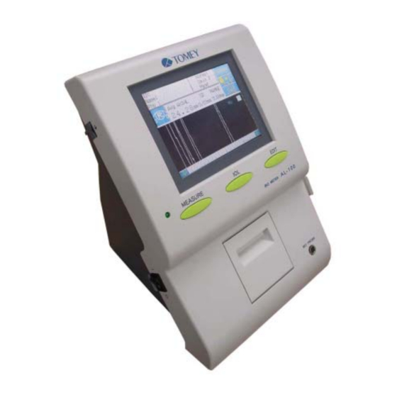
- Page 1 AL-100 Service Manual 2006. May. 31 ...
- Page 2 So you have to put back as same as initial condition. When you ask repair to TOMEY, please inform detail condition and symptoms. And if you change some setting, please put back it as same as initial condition.
- Page 3 Service BIO meter AL-100 Doc. No Manual 2. Trouble shooting. Symptoms Page Power lamp does not illuminate, when power switch turn ON. Trouble in Touch panel screen. Print out is not correct. <Page 02> ...
- Page 4 Service BIO meter AL-100 Doc. No Manual 3. Countermeasure. (1) Power lamp does not illuminate, when power switch turn ON. Cause1: Defective power supply cable. [Countermeasure]>>Check any damage on surface of the cable. And connect power supply correctly. Cause2: Defective fuse.
- Page 5 Service BIO meter AL-100 Doc. No Manual 4. How to disassemble. (1) Remove 6 sets of screws (M3*8) from rear cover. Remarks: Keep the washer that comes from bottom side of rear cover. (2) To remove rear cover, remove 6 sets of screws (M3*6) that hold rear cover.
- Page 6 Service BIO meter AL-100 Doc. No Manual (3) Remove connectors that connect main body with printer and button. And remove front cover. (4) Remove 6 sets of screws (M3*6) that hold shield LCD. <Page 05> ...
- Page 7 Service BIO meter AL-100 Doc. No Manual (4) Remove 4 set of screws (M3*6) that hold base LCD. (5) Turn LCD unit and hold it by hand. And remove 3 set of screws (M3*6) that hold shield LCD. <Page 06>...
- Page 8 Service BIO meter AL-100 Doc. No Manual (6) Disconnect all harnesses that connect main body and LCD. Now you can remove LCD from main unit. (7) Remove 3 sets of screws (M3*6) that hold shield LCD <Page 07> ...
- Page 9 Service BIO meter AL-100 Doc. No Manual (8) Remove 2 sets of screws (M2*15) that hold Inverter. (9) Disconnect all harnesses that come from Inverter. Now you can remove Inverter from LCD unit. <Page 08> ...
- Page 10 Service BIO meter AL-100 Doc. No Manual (10) Disconnect all harnesses that connect LCD and LCD board. (11) Remove 4 set of screws (M3*6) that hold LCD unit Remarks: When you remove right bottom side screw, you should use small head drive to avoid scratch LCD.
- Page 11 Service BIO meter AL-100 Doc. No Manual (12) Disconnect all harnesses that come from analog board. (13) Remove 3 sets of screws (M3*6) that hold analog board shield. Now, you can remove analog board from main unit. <Page 10> ...
- Page 12 Service BIO meter AL-100 Doc. No Manual (14) Disconnect all harnesses that come from analog board. (15) Cut the cable band, which fix cables beside of power supply board. (16) Remove 2 sets of screws (M3*6) that hold switching power supply on upper side.
- Page 13 Service BIO meter AL-100 Doc. No Manual (18) Disconnect all harnesses that come from Digital board. (19) Remove 4 sets of screws (M3*6) that hold Digital board. Now, you can remove Digital board from main unit. <Page 12> ...
- Page 14 Service BIO meter AL-100 Doc. No Manual 5. Parts List Parts number Parts Name Remarks 990-M001 Assy printer E02-0014 STN LCD 320*240 LCD & Touch panel Assy E38-0005 Inverter PH-BLC08-K3 714-030A Relay board 714-010A Digital board 714-050A Analog board 714-040A...
- Page 15 Service BIO meter AL-100 Doc. No Manual 6. Wiring Diagram <Page 14> ...
- Page 16 Service BIO meter AL-100 Doc. No Manual 7. LCD calibration (1) Go to “EDIT” mode by pushing “EDIT” button. (2) Keep pushing “EDIT” button till display is changed to LCD calibration mode. (3) Touch “ + “ key till you can hear twice beep sounds by small pen.
Need help?
Do you have a question about the AL-100 and is the answer not in the manual?
Questions and answers