Table of Contents
Advertisement
Quick Links
INSTRUCTION MANUAL
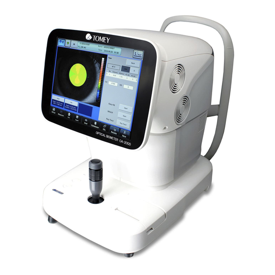
OPTICAL BIOMETER
OA-2000
Read this manual thoroughly before using the
instrument to ensure proper and safe operation.
Contact Tomey Corporation or our local distributor if
you have any questions or you encounter any
problems during operation.
■ Always follow the operation
procedures described in this manual.
■ Keep this manual in a readily
accessible location while operating the
instrument.
■ Contact our local distributor if you lose
this manual.
683A9090-0Q
Advertisement
Table of Contents

Related Manuals for Tomey OA-2000


Summary of Contents for Tomey OA-2000
- Page 1 OPTICAL BIOMETER OA-2000 Read this manual thoroughly before using the instrument to ensure proper and safe operation. Contact Tomey Corporation or our local distributor if you have any questions or you encounter any problems during operation. ■ Always follow the operation procedures described in this manual.
- Page 3 Never use the instrument for other purposes. ■ The external output terminal is not isolated from the internal circuit. Inappropriate wiring may damage the internal circuit. Be sure to contact Tomey Corporation beforehand when using the external output terminal. i-1 ■...
- Page 4 ■ This device complies with FCC RF radiation exposure limits set forth for an uncontrolled environment. The antenna used for this transmitter must be installed to provide a separation distance of at least 20 cm from all persons and must not be co-located or operated in conjunction with any other antenna or transmitter.
-
Page 5: How To Read This Manual
ii How to read this manual Outline This manual is structured as follows. 1. PRIOR TO USE Describes safety precautions and important information to be understood before installing and using the instrument. 2. NAMES AND FUNCTIONS Describes names and functions of each section of the instrument. 3. -
Page 6: Symbols Used In This Manual
SYMBOLS USED IN THIS MANUAL Descriptions accompanied by the symbols below indicate the following: ■ This is a precaution that, if unheeded, will result in a hazardous situation where there is an imminent danger of serious injury or death. ■ This is a precaution that, if unheeded, could result in a hazardous situation where there is a possibility of serious injury or death. -
Page 7: Table Of Contents
iii Contents Important Safety Information ......................... i-1 How to read this manual ........................ii-1 Outline ................................ii-1 SYMBOLS USED IN THIS MANUAL ......................ii-2 Contents ..............................iii-1 PRIOR TO USE ............................1-1 1.1 Precautions for operation ........................1-1 1.2 Checking package contents ........................1-5 1.3 Glossary .............................. - Page 8 3.8 Export, print, and save ......................... 3-58 3.8.1 Export ............................3-58 3.8.2 Printing ............................3-60 3.8.3 Saved data management ......................3-68 3.9 System setup ............................3-73 3.9.1 General ............................3-74 3.9.2 Measurement..........................3-76 3.9.3 Application ..........................3-81 3.9.4 Connection & Print ........................3-85 TECHNICAL INFORMATION ........................
-
Page 9: Prior To Use
1. PRIOR TO USE ■ Read this manual thoroughly before using the instrument to ensure proper and safe operation. ■ Always follow the operation procedures described in this manual. ■ Check that there are no devices that generate strong magnetic field near the instrument. A strong magnetic field may cause noise and affect measurement. - Page 10 IEC60601-1 ME system. Contact Tomey Corporation or our local distributor before connecting the instrument with a communication connector.
- Page 11 If problems such as smoke, offensive odor, or abnormal sound occur, immediately turn off the instrument, disconnect the power plug from the outlet, and contact Tomey Corporation or our local distributor. ■ Precautions after operation Do not place any container with liquid in it on the instrument. Any liquid entering the instrument may cause electric shock or failure.
- Page 12 Use the power cord and fuses provided with the instrument or specified by Tomey to ensure safety. Also, do not use the accessories provided with the instrument for other equipment. When any failure occurs in the instrument, indicate the failure in the instrument and contact our local distributor for inspection and repairs.
-
Page 13: Checking Package Contents
Be careful not to lift the instrument by directly holding the measuring head, chin rest, forehead pad, or joystick. The instrument may be damaged. Main unit Optical Biometer OA-2000 ..........1 Power cord ................... 1 Model eye ..................1 ... -
Page 14: Glossary
The unit of refractive power representing the level of myopia, hyperopia, or astigmatism. Reciprocal of the focal length measured in meters. [Data Transfer] System to output inspection data from Tomey products to digital files. [Easy IOL] Name of IOL power calculation software [Export] Transmits measurement data to TOMEY Link. - Page 15 Manual Alignment / Manual Measurement [OKULIX] IOL power calculation software that uses the ray tracing method.IOL power calculation software that uses the ray tracing method. We install this software in OA-2000 as an import agent. [OPT] Optical axial length measurement [OptLength] Optical distance from the tear to the retinal pigment epithelium.
- Page 16 [SPH] Spherical refractive power [D] [TOMEY Link] Digital medical record system to manage data measured with Tomey products. [VD (vertex distance)] Distance between corneal vertexes [mm] Represents the distance between the corneal vertex and the posterior surface of the lens to be prescribed.
-
Page 17: Overview
1.4 Overview This instrument is an ophthalmology device used to measure the length of living tissues utilizing light interference technology and to measure the cornea on captured images. This device is designed to measure the axial length, anterior chamber depth, corneal thickness, crystal lens thickness, radius of corneal curvature, and corneal shape at optical clinics. - Page 18 This page is intentionally left balnk. ■ 1-10...
-
Page 19: Names And Functions
2. NAMES AND FUNCTIONS 2.1 Physician's side (1) LCD and touch panel Displays the data or used to perform operations. The display angle can be adjusted. (2) Power lamp (3) Chin rest up/down button (4) Joystick Moves the head in all directions. A measurement button is provided on the top. -
Page 20: Sides Of The Main Unit
2.3 Sides of the main unit (1) Power socket (2) Power switch (3) Packing button Pressing this button for 3 seconds moves the (1) (2) (3) head to a set position in preparation for packing. (4) SD card slot (5) USB-H connector Connector for measurement unit, USB flash memory, and external ID input device (6) USB-D connector (PICT) -
Page 21: Screen
2.4 Screen 2.4.1 Basic structure and common items Varies depending on modes. (10) (1) Eye display field (eye selection button) (2) AL-4000 communication status field The status of communication with AL-4000 is displayed with icons. Communicating via Communicating Communication OMMUNICATION wireless access via USB stopped... -
Page 22: Screens In Optical Mode
2.4.2 Screens in optical mode a) Measurement screen (10) (11) (12) (13) (1) Inspection eye display field (2) Measurement data display (3) Measuring head position limit Appears when the measuring head is near the limit of its movable range. The bar appears at the top, bottom, right, or left of the screen according to the position of the measuring head. - Page 23 (10) Low reliability mark Any of the following symbols appear when the number of low reliability data sets exceeds the majority. When low reliability data sets have exceeded the majority: “!” in black When reliability of all data is low: “!” in pink When there are multiple higher peaks detected in the axial length measurement: “!”...
- Page 24 b) Axial length view screen (11) (12) (13) (10) (1) Display area selection button Enlarges and displays the image of the selected section. Axial length / anterior chamber depth, lens / corneal thickness / All (2) Axial length measurement data display (3) Scanned image / waveform display area (4) View screen switch button (5) Measurement data display...
- Page 25 c) Keratometer measurement view screen (12) (10) (11) (1) Ring projection image display field An image with rings projected is displayed. (2) View screen switch button (3) “Toric” button Displays the toric auxiliary functions. (4) Measurement position display selector Select the measurement position to be displayed. φ2.0mean / φ2.5 / φ3.0 When “φ2.0mean”...
- Page 26 d) Pupil diameter and corneal diameter view screen (1) Image display field (2) View screen switch button (3) Pupil diameter (4) Corneal diameter (5) "Apply" button (6) “Dual” button Displays the R/L alignment display screen. ■ 2-8...
-
Page 27: Screens In Each Ultrasound Mode
2.4.3 Screens in each ultrasound mode a) Axial length measurement screen (10) (1) Gain display/adjustment field (2) Mode display – Contact/Immersion (3) Waveform display area (4) Corneal gate cursor (only in immersion mode) The waveform on the right of this cursor position is measured as the waveform of the cornea. - Page 28 b) Axial length view screen (1) Axial length measurement data display Displays measurement conditions and measured axial length. (2) Measurement data display The axial length, anterior chamber depth, lens, and their average values are listed. (3) "Delete/Restore" button Deletes and recovers the measurement data. (4) "Select"...
- Page 29 c) Corneal thickness measurement screen (10) (12) (11) (1) Real-time data display field Displays the actual measurements of the loaded measurement points. The latest loaded data are displayed during a measurement process. (2) Corneal thickness data display (3) Measurement data display (4) "Delete/Restore"...
-
Page 30: Iol Power Calculation Screen
2.4.4 IOL power calculation screen (10) (11) (12) (15) (13) (14) (1) Parameter field Enter the following parameters used for calculating IOL power. Average Axial (axial length / ACD (anterior chamber depth) / K1 / K2 / Target Ref. (expected refractive power) (2) Clinical History Method parameter input field (3) Measurement mode display/measurement data type button... - Page 31 (13) "Personal Constant" screen display button (14) “Statistics” screen display button (15) “Page” button Touch the “Page” button to change the pages. 2-13 ■...
-
Page 32: Symbols Used For Marking
2.5 Symbols used for marking Refer to instruction manual. “ON” (power) “OFF” (power) Type B applied part Grounding (earth) ■ 2-14... -
Page 33: Operation Procedures
3. OPERATION PROCEDURES 3.1 Safety precautions ■ The power plug completely isolates the instrument from the commercial power source. If there is a problem with the instrument, turn off the power switch and disconnect the power plug. Install the instrument in a place where this can be performed smoothly. - Page 34 (Fig. 1) [Wireless connection] Refer to "3.2.2 Wireless communication connection with the axial length and corneal thickness measurement instrument AL-4000" to make settings. c) External digital printer ■ Use only the specified printer and cables. Use a video signal cable or remote cable to connect this instrument to a device conforming to IEC60601-1 or JIS T 0601-1 or conforming to IEC60950-1 and with a power source isolated by an insulated transformer.
- Page 35 (Fig. 1) f) Connecting the personal computer ■ The network support system “TOMEY Link” (optional) or the inspection data receiving software “DATA Transfer” (included in the package) is required for data communication with the Machine. ■ Refer to the corresponding operation manual for installation, settings, and operation of TOMEY Link and DATA Transfer.
- Page 36 Prepare the following items. - LAN cables (straight type, category 5 or higher) - A network hub (A 100MHz switching hub recommended) : 1 - A computer with TOMEY Link or DATA Transfer installed (Wiring example) LAN cable Systems in clinic...
- Page 37 2) Insert the USB plug into any of the USB-H connectors (1) on the side of the main unit, and insert the serial cable plug into the Communication Cable Terminal (2) on the back of AL-100. (Fig. 1 Side of OA-2000) (Fig. 2 Back of AL-100) 3-5 ■...
-
Page 38: Connecting The Axial Length And Corneal Thickness Measurement Instrument Al-4000
Stop emitting wireless waves and contact Tomey or our local distributor. ■ When this instrument causes wireless frequency interference harmful to a specified low power wireless station or amateur wireless station for wireless frequency identification, contact Tomey or our local distributor. -
Page 39: Turning The Power On And Adjustment After Turning The Power On
(Fig. 1) (Fig. 2) [Resuming communication from the no communication state] Click the “New” button (1) to clear the existing data. Select the same measurement mode as that of the AL-4000 using the “Setup” button (2). Click the “AL-4000 communication check” button (3) to resume communication. (Fig. -
Page 40: Switching Between Optical (Opt) Mode And Ultrasound (Us) Mode
“DATA Transfer” provided with the Machine is not available for query of the patient data. ■ For details on the TOMEY Link Server settings, refer to the TOMEY Link instruction manual. ■ Appropriate connection settings are required for connection with TOMEY Link. - Page 41 Enter the patient information using an external ID input device such as a barcode reader or the software keyboard (2) shown on the screen. After the patient ID is entered, touch the “Tomey Link Inquiry” button (3). The patient information is retrieved via Tomey Link and the result appears. When “Auto Inquiry”...
-
Page 42: Clear All Measurement Data (Preparation For Measuring A New Patient)
(Fig. 4) Touch the “No” button (8) on the confirmation screen (Fig. 4) or the “No” button on the Patient Information screen (Fig. 2) to ignore the entered data and return to the previous screen (Fig. 1). Entry of the patient ID from an external ID input device (barcode reader etc.) is accepted on the following screens. -
Page 43: Selecting An Eye
(Fig. 2) Select an eye and start new measurements. 3.2.7 Selecting an eye (Fig. 1) Touch either eye selection button (1) to select “R (right)” or “L (left)." 3.2.8 Patient's eye height adjustment ■ When moving the measuring head and/or chin rest of the instrument, pay attention to the position of the patient's face, hands, and fingers. -
Page 44: Optical Measurement Mode
3.3 Optical measurement mode Refer to “3.2.4 Switching between optical (OPT) mode and ultrasound (US) mode” for the method to switch to optical measurement mode. ■ Calibration may be conducted automatically in optical measurement mode in order to smoothly perform measurement.No operation is available during calibration.Restart the operation after the message “Calibrating…”... - Page 45 b) Selecting inspection eye Select the type of eye to be examined according to the patient’s eye. [Crystal lens] ●Phakic eye Select this in the case of phakic eyes. ●Aphakic eye Select this in the case of aphakic eyes. ●IOL (PMMA) Select this when a PMMA IOL is implanted.
-
Page 46: Alignment
3.3.2 Alignment ■ Do not allow any person to place their hands or fingers in the clearance under the measuring head or the section under the chin rest. Their hands or fingers may be caught and injured. ■ Measurement results may be affected if the patient’s eyelid and/or eyelashes cover the automatic alignment ring during measurement. - Page 47 (Fig. 1) Perform alignment in the Y axis. While pressing the center of the screen (3), the measuring head advances towards the patient. Touch the measuring head retract button (4) to retract the measuring head towards the physician. (Fig. 2) When the focus indicator (5) appears while Auto Alignment is activated, focusing in the Y axis starts automatically.
- Page 48 Clockwise The head rises. Counterclockwise The head lowers. (Fig. 1) (Fig. 2) Operate the joystick so the center of the pupil (1) enters the target ring (2). (Fig. 3) Move the joystick back and forth to move the measuring head so that the focus indicator (3) on the screen becomes small.
- Page 49 3.3.3 Measurement ■ Measure and display the selected measurement item only. Refer to “3.3.1 Setting measurement conditions” for selection method. ■ Be sure to touch the “New” button to delete all the measurement data of the previous patient before measuring another patient. If new measurement is started without deleting the previous data, the measurement data of the previous patient may be included.
- Page 50 (Fig. 1) When measurement has been completed, the measured data (2) appears. A representative value appears here. Press the “View” button (3) to look at all data taken for each measurement item. (Fig. 2) Touch the “Retake” button (4) for approximately 1 second until a beep sounds to delete the last measurement data and measure the same eye again.
-
Page 51: Browsing And Editing Axial Length Measurement
3.3.4 Browsing and editing axial length measurement Touch the "View" button (1) at the lower left of the measurement screen (Fig. 1) to open the axial length view screen (Fig. 2). Touch the “Measure" button (2) on the view screen (Fig. 2) to return to the measurement screen (Fig. - Page 52 b) Deleting and recovering measurement values (Fig. 1) Touch the “Delete” button (1) to delete the data selected with the cursor and the data color changes to gray. The data deleted here is excluded from the integral calculus value and average. To recover the deleted data, move the cursor to the data.
- Page 53 (Fig. 2) (10) (11) (5) (7) Select the display area (4).The following caliper lines will be displayed. Axial length : Front of cornea, retina Anterior chamber dept / lens : Front of cornea, front of crystal lens, back of crystal lens Corneal thickness : Front of cornea, back of cornea Touch the “Switch”...
- Page 54 d) Selecting specific measurement data to be used for calculating IOL power The average value is normally adopted for the measurement data to be used in calculating the IOL power, but specific measurement data can also be selected. (Fig. 1) Use the selection cursor movement buttons (1) to move the selection cursor (2) to the measurement data which is to be used in calculating the IOL power.
-
Page 55: Browsing Corneal Thickness Measurement Value And Correcting Intraocular Pressure
3.3.5 Browsing corneal thickness measurement value and correcting intraocular pressure (Fig. 1) Touch the “Pachy -> SNR” button (1) to switch the measurement data list between Pachy and SNR. Touch the “IOP" button (2) to open the intraocular pressure correction screen (Fig. -
Page 56: Browsing And Editing Keratometer Measurement
3.3.6 Browsing and editing keratometer measurement a) Browsing measurement values ■ The corneal irregular astigmatism display function is a simple measurement using keratometer measurement. This function does not detect all cases of corneal irregular astigmatism. Measurement itself or correct measurement may not be performed for some corneal shapes such as if there is a partial problem on the corneal shape. - Page 57 Touch the measurement position display button (2) to select the section to be displayed. φ2.0mean /φ2.5 /φ3.0 φ2.0mean displays only mean values. When measurement position φ3.0 is selected, the indexes of KAI and KRI (3) measured by keratometer measurement are displayed. KAI represents asymmetry of the corneal shape and KRI represents regularity (irregularity) of the corneal shape.
- Page 58 (Fig. 2) Measurement values (2) selected on the kerato view screen appear. In addition, the axis angle line for the characteristic point (green) and the IOL axis angle line (yellow) are shown on the camera image (3). Enter an angle to the Reference axis (green) (4) and IOL axis (yellow) (5) fields, and change positions of the corresponding lines on the camera image.
- Page 59 e) Topo Fourier function (Fig.1) Touch the “Fourier Map” button (1) on the Topo view screen to open the Topo Fourier screen (Fig. 2). (Fig.2) On the Topo Fourier analysis screen, the constant term is displayed as “Spherical equ.,” the first order term as “Asymmetry,” the second order term as “Regular astigmatism,”...
-
Page 60: Browsing And Editing Pupil Diameter And Corneal Diameter Measurement Values
3.3.7 Browsing and editing pupil diameter and corneal diameter measurement values (Fig. 1) Touch the "DIA" button (1) on each view screen to open the pupil/corneal diameter view screen (Fig. 2). (10) (Fig. 2) Measured pupil diameter (2) and corneal diameter (3) are shown. The fitting circle and center point for analyzing the pupil diameter, and measurement lines for analyzing the corneal diameter are shown on the CCD image. -
Page 61: Ultrasound Axial Length Measurement Mode
3.4 Ultrasound axial length measurement mode Refer to “3.2.4 Switching between optical (OPT) mode and ultrasound (US) mode” for the method to switch to ultrasound measurement mode. 3.4.1 Setting measurement conditions ■ Settings made here are only effective for the eye currently selected. Settings cannot be made for both eyes simultaneously. - Page 62 ● User Setting Select this when registering optional materials for IOL eyes. Register the settings on the converted acoustic velocity setting screen. (Refer to “Setting converted acoustic velocity.”) “Anterior chamber depth” and “lens” are not measured for an aphakic eye and “lens”...
- Page 63 (Initial setting and setting range of converted acoustic velocity) ● Phakic eye Average acoustic velocity for axial length : 1,550m/s, 1,500 - 1,600m/s Crystal lens acoustic velocity : 1,641m/s, 1,540 - 1,740m/s Anterior chamber depth acoustic velocity : 1,532 m/s, 1,430 - 1,630m/s Vitreous acoustic velocity (divisional velocity only) : 1,532 m/s, 800 - 2,000 m/s ●...
-
Page 64: Measurement
3.4.2 Measurement See the user’s manual of the AL-4000 for the actual measurement procedure. This section describes the operations that can be performed with this instrument during measurement. ■ The converted acoustic velocity directly affects the measurement data. Check that the desired value is set before starting measurement. ■... - Page 65 b) Setting gate cursor ■ Settings made here are only effective for the eye currently selected. Settings cannot be made for both eyes simultaneously. Complete necessary settings for each eye. (Fig. 1) Select a gate cursor to be adjusted by touching the gate selection buttons (1). The selected and active cursor is displayed in red but the other cursors are displayed in white.
-
Page 66: Checking Waveforms After Measurement
3.4.3 Checking waveforms after measurement a) Displaying waveform of arbitrary measurement data (Fig. 1) When all necessary measurement data is captured or when the “View” button (1) is touched, the edit screen (Fig. 2) opens. (Fig. 2) 2) The waveform measured at the selected cursor (2) is displayed in the waveform display field (3). - Page 67 Touch the “Delete” button (1) to delete the data selected with the cursor and the data color changes to gray. The data deleted here is excluded from the average. To recover the deleted data, move the cursor to the data. Touch the “Recall” button (2) to cancel deletion.
- Page 68 d) Caliper function ■ Values measured and displayed using the caliper function are rough estimates and may differ from the actual measurement result. This function is used to measure the distance of the measurement waveform. Three dotted caliper lines (four lines in immersion mode) appear and the distance to the selected caliper line is displayed.
- Page 69 ● In contact lens mode (Fig. 3) The distance between the start line of the waveform (0 mm point) (10) and the retina caliper line (13) is shown in the axial length field, that between the start line of the waveform (10) and the caliper line for the front of the crystal lens (11) is shown in the ACD (anterior chamber depth) field, and that between the caliper lines for the front of the crystal lens (11) and for the back of the crystal lens (12) is shown in the Lens field.
- Page 70 When the “Select” button (3) is touched, it is selected as the data to be used in calculating the IOL power, and a “*” appears on the left of the data. ■ 3-38...
-
Page 71: Ultrasound Corneal Thickness Measurement Mode
3.5 Ultrasound corneal thickness measurement mode Refer to “3.2.4 Switching between optical (OPT) mode and ultrasound (US) mode” for the method to switch to ultrasound corneal thickness measurement mode. 3.5.1 Setting the data type to be displayed Select the measurement data type to be displayed from the following three options. ●... - Page 72 b) Selecting measurement values to be displayed Select measurement values to be displayed from the following 2 options. ● Actual measurement ● Bias value c) How to display converted acoustic velocity and bias values Select how to display the bias value from the following two options. ●...
-
Page 73: Displaying And Setting Measurement Points
d) Measurement mode Set the measurement mode. ● Auto ● Manual Select manual measurement when it is difficult to measure in Auto mode or when measurement values are captured while not performing a measurement. Refer to the AL-4000 Instruction Manual. 3.5.3 Displaying and setting measurement points This function displays and sets the location of measurement points. -
Page 74: Measurement
Touch the “Change Meas. Point” button (3) to open the measurement point change screen (Fig. 3) to change the measurement point. (Fig. 3) When the desired input field on the measurement point change screen (Fig. 3) is touched, the field is activated. Set values using the keypad and the like. As for the setting of “S/I,”... -
Page 75: Checking The Measurement Data
a) Re-measurement of the same patient ■ The deleted data cannot be restored. Carefully check the data before deleting it. Retain the patient information and delete only the measurement data for each eye. Delete all data referring to “3.2.6 Clear all measurement data (preparation for measuring a new patient)”... - Page 76 (Fig. 2) The input fields of the parameter 1 (3) and parameter 2 (4) for the intraocular pressure correction formula become active when touched, and the keypad appears. Also, when a formula selection button is touched, the already set parameters are displayed in the intraocular pressure correction formula. [Input range] ■...
- Page 77 c) Caliper function The caliper function is for temporary reference and cannot store the callipered data. (Fig. 1) Touch the "Caliper" button (1) to display the caliper screen (Fig. 2). (Fig. 2) Touch the “Switch” button (2) to select a caliper line to be adjusted. The active caliper line is displayed in red and the other caliper line in yellow.
- Page 78 1) Touch the “Differential” button (1) to open the subtraction display screen (Fig. 2). When a measurement has already been completed at this point, the measured values are displayed in the data 1 display field (2). (Fig. 2) 2) The measurement data being stored can be selected as Data 1 or Data 2. Touch the "Memory Data"...
-
Page 79: Iol Power Calculation
3.6 IOL power calculation ■ When using biometry results for calculation of the IOL power, the physician must examine the measurement result beforehand. ■ Calculation by this instrument may cause some errors due to the number of significant digits in internal calculations. ■... -
Page 80: Setting The Eye To Be Measured
(Fig. 3) 3.6.1 Setting the eye to be measured TRefer to “ 3.2.7 Selecting the eye ” 3.6.2 IOL power calculation 3.6.2.1 Entering calculation parameters a) Axial length and anterior chamber depth When an axial length and anterior chamber depth measurement is completed, the measurement data is already entered automatically and cannot be entered manually. - Page 81 b) Corneal refractive power and radius of corneal curvature (K1/K2) When keratometer measurement is completed, the measurement data is already entered automatically and cannot be entered manually. (Refer to “3.4.3 e) Selecting specific measurement data to be used for calculating IOL power.") When measurement has not yet been performed, enter the data as follows.
- Page 82 (Fig. 1) ■ Entering using keypad The lens constants a0, a1, and a2 in the Haigis optimized formula cannot be entered directly using the keypad. Refer to “Entering through IOL data list” below. (Fig. 2) 1) Touch an input field (1) to activate it. The keypad (2) appears. Touch the “Enter”...
- Page 83 2) You can check the registration content by sliding the IOL data list being displayed with the scroll bar (3). Select data using the “IOL data selection” buttons (4). 4) Touch the "Edit" button (5) to display the screen for editing the registration content.
- Page 84 3.6.2.2 Setting calculation formula Touch the calculation formula pull-down button (1) and select a formula. The following 9 types of IOL power calculation formulae are provided with this instrument. IOL calculation formulae listed in the pull-down menu can be set according to “3.9.3.b) Selecting IOL power calculation formula.”...
-
Page 85: Okulix
3) When the “Personal Constant” button (5) is touched, the Personal Value screen (Fig. 2) appears. Touch the “Print” button (6) to print the personal constants only. Touch the “Close” button (7) to close the Personal Value screen and return to the previous screen. (Fig. - Page 86 (Fig. 1) c) Entering target Ref. (Fig. 1) 1) Touch the Target Ref. input field (1) to activate it. The keypad appears. Enter the data and touch the “Enter” key on the keypad to apply the data. The entered value is stored in the main unit, and is not cleared even when the power is turned off.
- Page 87 (Fig. 2) 1) Touch the IOL data field (1). The IOL List screen (Fig. 2) appears and allows you to select the desired IOL data. Select the data and touch the “Apply” key (2) to apply the data. The entered value is stored in the main unit, and is not cleared even when the power is turned off.
-
Page 88: Statistical Processing
3.7 Statistical processing ■ The lens constant registered on this screen will be used for the next IOL calculation. Carefully check the data before registration. Statistical processing can be performed on this screen using the examination data accumulated in the facilities. Predictive errors when using the registered lens constant are calculated and the histogram is displayed. - Page 89 2) After all the conditions are set, touch the “OK” button (2). Statistical processing is performed and the result appears on the right side of the screen. The histogram (3) in the upper section shows registered lens constants and the statistical processing results of those lens constants. When lens constants are not registered, the result does not appear.
-
Page 90: Export, Print, And Save
In addition, when data was sent to TOMEY Link, all the data without ID number are regarded as the data of the same patient so that they must be handled with great care to avoid mishandling. - Page 91 Touch the “Export” button (1) to open the Transmission confirmation screen (Fig. 2). (Fig. 1) (Fig. 2) The transfer confirmation screen (Fig. 2) displays patient ID, patient name, and sex. Touch the "Send" button (2) to start sending data. Touching the "Cancel" button (3) returns you to the previous screen without sending data.
-
Page 92: Printing
3.8.2 Printing The printer and printing type can be selected in the system setup. Refer to “3.9.4 b) Selecting and setting printer.” ■ Different waveforms are printed depending on the screen. Optical mode Measurement screen : Waveform No. 1 is printed. View screen : Waveform displayed on the screen is printed. - Page 93 b) Example of printout for optical (axial length, anterior chamber depth, lens, corneal thickness) 1) Inspected eye (right eye/left eye) 2) Measurement method 3) Inspection eye 4) Measurement mode Auto (A) / Manual (M) 5) Fitting Immersion / Contact / Optical length 6) Average axial length 7) Average optical distance 8) Standard deviation of axial length...
- Page 94 c) Example of printout for optical measurement (kerato) Inspected eye (right eye/left eye) Kerato measurement position Selected measurement value Keratometer average value Corneal astigmatism Measurement value Low reliability mark Memory number of representative value Corneal irregular astigmatism index 10) Corneal irregular astigmatism angle (10) d) Example of printout for optical measurement (pupil/corneal diameter)
- Page 95 e) Example of printout for ultrasound measurement (axial length) [AL-4000] Inspected eye (right eye/left eye) Measurement method Inspection eye Converted sonic velocity Gain Average axial length Standard deviation of axial length Difference between shortest axial length and longest axial length Average anterior chamber depth (10) 10) Average lens thickness...
- Page 96 [AL-100] Inspected eye (right eye/left eye) Model of measuring instrument Patient’s eye Converted sonic velocity Axial length ACD (anterior chamber depth) Lens thickness Waveform ■ 3-64...
- Page 97 f) Example of printout for ultrasound measurement (corneal thickness) Inspected eye (right eye/left eye) Model of measuring instrument Measurement mode / Type of displayed data Converted acoustic velocity Actual measurement in each memory slot Measurement point of measurement data Average of actual measurements Standard deviation of actual measurements Bias value display method and...
- Page 98 g) Printout of IOL power calculation Inspected eye (right eye/left eye) US/OPT display Axial length ACD (anterior chamber depth) Corneal refractive power or radius of corneal curvature Cornea equivalent refractive index Target Ref. after surgery Parameters printed when SRK/T Double K is selected Formula name 10) IOL model name 11) Lens constant...
- Page 99 h) Printout of personal constants Inspected eye (right eye/left eye) Eye refractive power after surgery Power of the implanted IOL Axial length ACD (anterior chamber depth) Corneal refractive power or radius of corneal curvature Lens constant Parameters for SRK/T Double K Calculation result 3-67 ■...
-
Page 100: Saved Data Management
3.8.3 Saved data management a) Selecting storage The internal memory of this instrument or external memory connected to this instrument can be selected. Set the storage referring to “3.9.4 c) Media options / Data output format.” When the internal memory is selected for storage, the used storage capacity is shown as a % on the button. - Page 101 (Fig. 3) When characters are entered in the search field (3), the patient ID and name are searched and the result appears. Touch the title of the line (4) to change the order of the list. Touching this button sorts the data in ascending order or descending order.
- Page 102 d) Deleting saved data ■ When any patient information is deleted, all the measurement data saved with the patient ID is also deleted, regardless of the mode being displayed. Be sure to check the contents saved before deleting them. [Delete all on Database screen] Touch the “Format”...
- Page 103 e) Transferring saved data ■ Some USB flash memories are not recognized when connected to this instrument. When an external memory is connected to this instrument, the data saved in the internal memory can be transferred to the external memory. Touch the “Move Data”...
- Page 104 f) Changing ID ■ Examination data are saved or deleted when changing ID. Do not turn off the power when ID is being changed. Otherwise, the data may be damaged. Backup the data as necessary. ■ Be sure to confirm the change before changing the ID. Hold the grayed out patient information button (1) briefly on the view screen to open the patient information entry screen (Fig.
-
Page 105: System Setup
3.9 System setup Touch the “System Setup” button (1) on the Setup screen (Fig. 1) in each mode to open the System Setup screen (Fig. 2). (Fig. 1) (Fig. 2) The system setup consists of 4 major categories. ● General ......Language, time, version information, etc. ●... -
Page 106: General
3.9.1 General Set common items here. Select the General tab. (Fig. 1) (10) (Fig. 2) (11) (12) (13) (14) (Fig. 3) (1) System Ver. Displays the version information. The version information of the ultrasound measurement unit AL-4000 is also displayed. (2) Language Selects the language. - Page 107 “1”, the characters from the very beginning are identified as the ID number. (14) Confirmation Use this field to display the Patient information confirmation screen when saving the inspection data or sending the inspection data to TOMEY Link. 3-75 ■...
-
Page 108: Measurement
3.9.2 Measurement Make settings related to measurement on this screen. Select the Measurement tab. a) Optical Measurement Mode - Selection Select measurements to be performed in optical mode. Touch the “Selection” button (1) to open the measurement mode setup screen (Fig. 2). (Fig. - Page 109 c) Settings for various measurements (Fig. 1) [Optical] Axial Pachy / Kerato : Opens the setup screen for optical measurement of axial length and corneal thickness. Kerato : Opens the setup screen for keratometer measurement. [Ultrasound] Axial : Opens the setup screen for ultrasound measurement of axial length.
- Page 110 (2) Eye Type User Setting Set the average refractive index of the eye to be measured. (3) Default itting formula Set the fitting formula for normal operation. This selection changes the default view for the kerato measurement position. Immersion: φ2.5 mm Other fitting fomula: φ3.0 mm (4) Measurement Times Set the number of data sets taken per measurement.
- Page 111 (4) AXIS Step (unit for angle) Sets the display units for the corneal astigmatism axial angle. 1° / 5° (5) Measurement Times Set the number of data sets taken per measurement. 10 data x 1 time Load 10 data sets once. 5 data x 2 times Load 5 data sets twice.
- Page 112 [Ultrasound – Pachy] (Fig. 1) (Fig. 2) (1) Data Selection Method Select the measurement data type to be displayed. Latest / Minimum / Average (2) Measure Point Opens the measurement setup screen (Fig. 2). (3) PreSet1 / PreSet2 Changes the selected preset measurement point. (4) Eye selection Changes the preset measurement point of the selected eye.
-
Page 113: Application
3.9.3 Application Make settings related to measurement of calculation, correction, etc. Select the Application tab. a) Registering IOL data Registers the IOL data to each measurement method. Touch each button to open the corresponding registration screen (Fig. 2). (Fig. 1) (Fig. - Page 114 b) Selecting IOL power formula Select the IOL formula to be used on the IOL power calculation screen. The selected formulae will be displayed in the pull-down menu on the IOL power calculation screen. Touch the “Selection” button to open the IOL Formula Selection screen (Fig.
- Page 115 (1) Intraocular pressure correction formulas Register the intraocular pressure correction formula to be used for the intraocular pressure correction. Input range IOP correction formula name Up to 10 characters Parameter 1 0 - 1500 Parameter 2 0.0000 - 1.0000 (2) Indication Unit mmHg / hPa (3) CCT (Ultrasound) Set the CCT ultrasound correction value.
- Page 116 (3) Touch the “Update" button (1). The update confirmation screen appears. Touch the “OK” button. OKULIX is updated. (Fig.3) ■ 3-84...
-
Page 117: Connection & Print
3.9.4 Connection & Print Make settings related to connection, saving, export, and printing on this screen. Select the Connection & Print tab. a) Setting functions of save, export, and print buttons Assign functions to 2 buttons for saving, export, and print provided on each screen (Fig. - Page 118 b) Selecting and setting printer The printer used for printing can be selected here. The built-in printer, video monochrome printer, video color printer, PictBridge printer, or network printer can be selected. Touch the “Setting” button to open the Setup screen for each printer. There are no setting items for the video color printer. (Fig.
- Page 119 (4) IOL Window (IOL power calculation screen) Make settings for printing from the IOL power calculation screen. Touch the “Setting” button to open the System Setup screen (Fig. 2). IOL data number 3 / 9 / 15 AppendingMeasurement data Yes / No Select Calculation Result at Yes / No Printing...
- Page 120 [PictBridge printer setting] (Fig. 1) (1) Paper Size L / A4 / B5 Form 1 / B5 Form 2 B5 Form 1: When the paper feed tray is centered. B5 Form 2: When the paper feed tray is left-aligned. [Network printer setting] (Fig.
- Page 121 (4) B/W Reverse of Opt wave image Selects whether to reverse a waveform image black and white to be exported to Data Transfer/Tomey Link. Select ON to display the waveform in black on the white background. Select OFF to display the waveform in white on the black background.
- Page 122 ID is retrieved.[Setting Data Transfer printer] (3) Login TOMEY Link Set the user ID and password to log in to the TOMEY Link. Maximum number of characters to be entered for the user ID or password is 16.
- Page 123 (4) Host IP address Set the IP address of the PC to be connected. Touch the “DNS” button to specify the PC name. A DNS server must be running in the LAN environment to enable connection using the DNS. Touch the input field to display the keyboard. (5) Port number A port number can be set.
- Page 124 e) CASIA2 communication setting Select the ultrasound biometer and make settings for wireless communication with the ultrasound measurement unit AL-4000. Connection can be established automatically upon startup of the instrument when the information of the AL-4000 to be connected is registered in the connection location list and “Permit” is selected for Wireless Communication.
- Page 125 (1) Connection permission Enable / Disable (2) My BD Address The BD address of this instrument is displayed. (3) Connecting Place Name; Connecting BD Address The connecting location name and BD address currently connected are displayed. These fields are blank when nothing is connected. (4) Connection List Register connecting locations.
- Page 126 Default Gateway. (2) “IP Check” button Performs a duplicate IP address check. ■ When only this instrument and the TOMEY Link Server or a computer running Setting Data Transfer are connected to the network, the following settings can be examples used.
-
Page 127: Technical Information
4. TECHNICAL INFORMATION 4.1 IOL power calculation formula 4.1.1 Haigis Standard / Haigis optimized 1. Implanted IOL power (D) 1000 1000 Where: 1000 d = a0 + a1・ACD + a2・L (ACD ≠ 0) d =(a0 –... -
Page 128: Hoffer ® Q Formula
: Vertex distance (mm) = 12 : Implanted IOL power (D) : 0.4…※ : 0.1…※ * The Haigis optimized formula uses the registered a0, a1, and a2 for calculation. 3. Personal A-Constant (ACD≠0) 62467 ... - Page 129 Where: 1336 1000 : Predicted anterior chamber depth after surgery (ACD) = X + Y Where: X = C1 + 0.3 × (L – 23.5) + (tan K) Y = 0.1M × (23.5 - L) ×...
-
Page 130: Holladay 1
4.1.3 Holladay 1 1. Implanted IOL power (D) 1000 2. Predicted refractive power after surgery (D) ... -
Page 131: Srk/T Formula
3. Personal SF ・ } Where: AQ = (nc-1) - 0.001AREF {V(nc - 1) - r} BQ = 0.001AREF {L2・V(nc - 1) - r(L2 - V・na)} - {L2(nc - 1) + na・r} CQ1 = 0.001AREF[V{na・r - L2(nc - 1)} + L2・r] CQ2 = 1000na{na・r –... - Page 132 : Calculated corneal diameter (mm) = -5.41 + 0.58412LC + 0.098K : Corrected axial length (mm) L ≦ 24.2 → LC = L L > 24.2 → LC = -3.446 + 1.716L - 0.0237L : Estimated anterior chamber depth after surgery (mm) = H + Ofst.
-
Page 133: Srk Showa Formula
β : P [na・r + L1 (nc – 1) + 0.001AREF {L1・r + V・L1 (1 – nc) - na・V・r }] : na [1000X – P・L1・r + AREF {0.001P・V・L1・r – (V・X + L1・r)}] AREF : Refractive power of eye after surgery (D) 4.1.5 SRK SHOWA formula 1. -
Page 134: Shammas-Pl Formula
4.1.6 Shammas-PL formula 1. Implanted IOL power (D) for emmentropization 1336 emme 0125 1336 2. Implanted IOL power (D) for ametropia 1336 amet ... -
Page 135: Srk/T Double K
AREF: Eye refractive power after surgery (D) 4.1.7 SRK/T Double K 1. Implanted IOL power (D) for emmentropization 1000 emme 2. Implanted IOL power (D) for ametropia 1000 ... - Page 136 : Average corneal refractive power (D) before refractive correction surgery = (K1 + K2 : Radius of corneal curvature (mm) before refractive correction surgery = {(KI - 1) × 1000}/ K : Cornea equivalent refractive index : Average corneal refractive power (D) after refractive post correction surgery = (K1...
-
Page 137: Verification When Measuring Axial Length
4.2 Verification when measuring axial length Retinal OA-2000 measures the distance from the lacrimal pigment fluid on the corneal surface to the retinal pigment epithelium epithelium (RPE) as the axial length. Normally, the waveform height and width of the internal limiting membrane and choroid are smaller than those of the retinal pigment epithelium. -
Page 138: Ultrasound Conversion Formula
4.3 Ultrasound conversion formula The axial length measurement displayed in Contact mode or Immersion mode of OA-2000 is the value calculated by converting the optically obtained axial length to an ultrasound axial length value, using a correction formula developed based on clinical results. Therefore, the... -
Page 139: Verification When Measuring Anterior Chamber Depth And Crystal Lens Thickness
4.4 Verification when measuring anterior chamber depth and crystal lens thickness Front of crystal lens Back of crystal lens Anterior of cornea Waveform of cortex etc. Waveform that clearly Waveform of the rear side of the crystal lens is small. shows the front of the cornea Waveform that... -
Page 140: Corneal Irregular Astigmatism Index
4.5 Corneal irregular astigmatism index Corneal irregular astigmatism index This is the index that simply quantitates the data of the corneal irregular astigmatism which cannot be found by ordinary keratometer measurements (K1, K2, and AX) according the keratometory image. There are 2 indexes (KAI and KRI) as shown below, and each of them shows the level of irregular astigmatism. -
Page 141: Inspection And Maintenance
This warranty also shall NOT apply if the product has not been installed, operated or maintained in accordance with the INSTRUCTION MANUAL of Tomey Corporation (here in after called “Tomey”). Neither seller not Tomey shall be liable for any damages caused by purchaser's failure to follow instruction for proper installation, use and maintenance of product. -
Page 142: Routine Maintenance
5.4 Routine maintenance ■ Hold the plug when disconnecting the power plug from the outlet to avoid placing excessive force on the cord. Pulling the cord may damage the inner core wires, resulting in electric shock or fire. ■ Do not use organic solvents such as thinner, benzene, or acetone to clean the instrument. -
Page 143: Replacing Consumables
Install the fuse holder in the reverse order of removal. 5.5.2 Printer paper ■ Always use genuine Tomey paper for the printer. Using other types of paper may cause printer failure. ■ Do not pull paper forcibly. Trying to pull the paper out may cause printer failure. -
Page 144: Storing
5.6 Storing ■ Install the instrument in a location free of water or chemicals. Any water or chemicals entering the instrument may cause an electric shock or failure. ■ Do not store the instrument in a location where chemicals are stored or gases may occur. -
Page 145: Troubleshooting
6. TROUBLESHOOTING Check the following first when you encounter any problems. If the problem is not solved even after checking the applicable item listed below, contact our local distributor to request inspection and/or repair. ■ Do not remove the cover of the instrument. You may be directly exposed to high voltage sections. - Page 146 The whole monitor screen is dark and not easy to see. The brightness of the monitor is low. Adjust the brightness of the screen using the brightness setting of the screen described in "3.9.1 General." The clock displayed is stopped. Stored data is displayed.
- Page 147 The data cannot be printed by the built-in printer. Printer paper. Check for the remaining of printer paper. Verify that printer paper is set correctly as described in "5.5.2 Printer paper." Setting the output printer Set "built-in printer" to the destination to which output is directed when "Print button"...
- Page 148 A screen which does not receive an ID input appears. Entry of ID from an external ID input instrument is accepted only on a screen where the patient information is displayed. Input ID after displaying such screens. Data cannot be saved in the internal memory. The ID is not entered.
-
Page 149: Optical Measurement
6.2 Optical measurement Measurement cannot be performed. Stable measurements cannot be obtained. Measurements are largely different from those taken before. The measurement window is dirty. Check that the measurement window is clean. A problem has occurred in the instrument. Contact our local distributor. - Page 150 Measurements are unstable or inappropriate. The converted acoustic velocity is not set appropriately. Check the setting of the converted acoustic velocity. A different converted acoustic velocity can be set for right and left eyes. Check the setting for both eyes. The retina waveform gate cursor is not set in an appropriate position.
-
Page 151: Consumables And Optional Equipment
The following spare parts and accessories are available from our local distributor of this instrument. Contact our local distributor to order them. ● Printer paper Specify the paper type as "Built-in printer paper for OA-2000." ● Chin rest paper (100 sheets/set) ● Fuse Specify the part type as “OA-2000 fuse.”... - Page 152 This page is intentionally left balnk. ■ 7-2...
-
Page 153: Specifications
8. SPECIFICATIONS 8.1 Specifications 8.1.1 Optical Measurement ● Measurement range Axial length : 14 - 40mm Anterior chamber depth : 1.5 - 7.0mm Crystalline lens thickness : 0.5 - 6.0mm Corneal thickness : 0.2 - 1.2mm Corneal curvature radius : 5.0 - 11mm Pupil diameter : 1.5 - 13mm Corneal diameter... -
Page 154: Energy Information
8.2 Energy information Measurement light source ■ Maximum power 980μW 8.3 Operating environment Operate the instrument under the following environmental conditions. ■ Installation : Indoors, not in direct sunlight ■ Temperature : +10~+35℃ ■ Humidity : 30~90% ■ Atmospheric pressure : 800~1060hPa ■... -
Page 155: Declaration Of Conformity To Emc
8.5 Declaration of Conformity to EMC ■ The OA-2000 belongs to Group 1 and B equipment in accordance with IEC/EN60601-1-2. ■ The OA-2000 is a group 1, class B product according to EN55011(CISPR11). This means that the OA-2000 does not generate and/or use intentionally... - Page 156 Cable List No. Cable Maximum length [m] Remarks AC code Unshielded Accessory List No. Name Model Manufacture AC code KP-300C/VCTF KAWASAKI ELECTRIC 3×0.75mm /KS-16Y (oversea 200V package) WIRE CO.LTD ● Basic performance ・Measurement data of axial length, anterior chamber depth, corneal curvature radius and corneal thickness are indicated properly.
- Page 157 Table 201 The OA-2000 is intended for use in the electromagnetic environment specified below. The customer or the user of the OA-2000 should assure that it is used in such an environment. Emissions test Compliance Electromagnetic environment - guidance...
- Page 158 Table 202 The OA-2000 is intended for use in the electromagnetic environment specified below. The customer or the user of the OA-2000 should assure that it is used in such an environment. Immunity test IEC 60601 test Compliance level...
- Page 159 Guidance and manufacturer's declaration electromagnetic immunity Table 204 The OA-2000 is intended for use in the electromagnetic environment specified below. The customer or the user of the OA-2000 should assure that it is used in such an environment. Immunity test IEC 60601 test Compliance...
- Page 160 OA-2000 Table 206 The OA-2000 is intended for use in an electromagnetic environment in which radiated RF disturbances are controlled. The customer or the user of the OA-2000 can help prevent electromagnetic interference by maintaining a minimum distance between portable and mobile RF communications equipment (transmitters) and the OA-2000 as recommended below, according to the maximum output power of the communications equipment.
- Page 161 Fax: +81 52-561-4735 EC-Representative Tomey GmbH Wiesbadener Straße 21 90427 Nürnberg, Germany Tel: +49 911-9385462-0 Fax: +49 911-9385462-20 AUTHORIZED TOMEY SERVICE CENTERS Headquarters, Pacific Rim Tomey Corporation 2-11-33 Noritakeshinmachi Nishi-ku, Nagoya 451-0051 JAPAN Tel: +81 52-581-5327 Fax: +81 52-561-4735 Europe Tomey GmbH Wiesbadener Straße 21...
- Page 162 0120...
Need help?
Do you have a question about the OA-2000 and is the answer not in the manual?
Questions and answers