Table of Contents
Advertisement
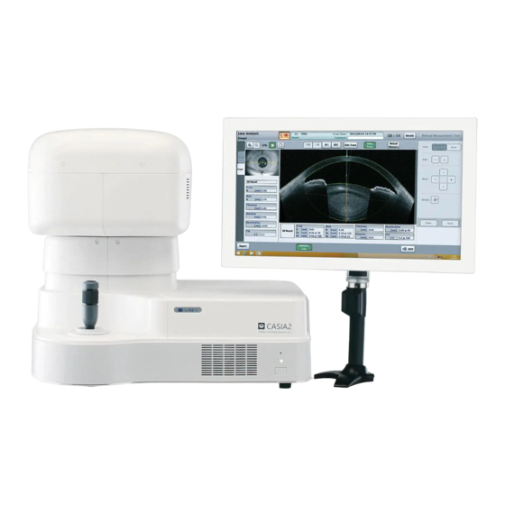
INSTRUCTION MANUAL
Cornea/Anterior Segment OCT
Read this manual thoroughly before using the instrument
to ensure proper and safe operation.
Contact Tomey Corporation or your local distributor if
you have any questions or you encounter any problems
during operation.
■
■
■
CASIA2
Always follow the operation procedures
described in this manual.
Keep this manual in a readily accessible
location while operating the instrument.
Contact your local distributor if you lose
this manual.
686A9090-2F
Advertisement
Table of Contents
Troubleshooting

Subscribe to Our Youtube Channel
Related Manuals for Tomey CASIA2


Summary of Contents for Tomey CASIA2
- Page 1 Cornea/Anterior Segment OCT CASIA2 Read this manual thoroughly before using the instrument to ensure proper and safe operation. Contact Tomey Corporation or your local distributor if you have any questions or you encounter any problems during operation. Always follow the operation procedures ■...
- Page 3 i. Important safety information Do not install this instrument in a location where explosives or ■ flammable substances are used or stored. Fire or explosion may occur. Do not remove the cover of the instrument. Otherwise electric shock ■ may occur. Do not disassemble or modify the instrument.
- Page 4 The terminal for connecting the instrument to external devices is not ■ isolated from the internal circuit. Inappropriate wiring may damage the internal circuit. Contact Tomey or your local distributor before using the instrument connected to another device. When operating this instrument connected to other devices not ■...
-
Page 5: How To Read This Manual
ii. How to read this manual Outline This manual is structured as follows. 1. PRIOR TO USE Describes safety precautions important information to be understood before installing and using the instrument. 2. NAMES AND FUNCTIONS Describes names and functions of each section of the instrument. -
Page 6: Symbols Used In This Manual
Symbols used in this manual Sentences accompanied with the symbols below indicate the following: This is a precaution that, if unheeded, will ■ result in a hazardous situation where there is imminent danger of serious injury or death. This is a precaution that, if unheeded, could ■... -
Page 7: Table Of Contents
iii. Contents i. Important safety information ................... i-1 ii. How to read this manual ..................ii-1 Outline ..........................ii-1 Symbols used in this manual .................... ii-2 iii. Contents ....................... iii-1 1. PRIOR TO USE ..................... 1-1 1.1 Precautions for operation ..................1-1 1.2 Checking package contents .................. - Page 8 3.1.1 Precautions for installing the instrument ............. 3-1 3.1.2 Precautions for connecting the power cord ............3-2 3.1.3 Connecting the power cord and other cables ............. 3-3 3.2 Starting up/shutting down the instrument ..............3-4 3.3 Measurement ......................3-5 4. TECHNICAL INFORMATION ................4-1 5.
-
Page 9: Prior To Use
1. PRIOR TO USE Read this manual thoroughly before using this ■ instrument to ensure proper and safe operation. Always follow operation procedures ■ described in this manual. Check that there are no devices that generate a ■ strong magnetic field near the instrument. A strong magnetic field may cause noise and affect measurement. - Page 10 Conduct grounding work correctly. Otherwise, electric shock may occur. Do not connect a device with data transmission specifications that are not compatible. Fire or electric shock may occur. Contact Tomey Corporation or your local distributor before using the instrument. ■...
- Page 11 Do not hold the head, chin rest, forehead pad, joystick, or cables when moving the instrument. These components are detachable and the instrument may drop, resulting in injuries. Install the instrument in a location not subject to direct sunlight, high temperature and humidity, or air containing dust, salt, and/or sulfur.
- Page 12 If any smoke, offensive odor, or abnormal sound occurs, turn off the instrument immediately, disconnect the power plug from the outlet, and contact your local distributor or Tomey Corporation. Precautions after operation ■...
- Page 13 Otherwise, electric shock may occur, resulting in death or serious injuries. Use the power cord and fuses provided with the instrument or specified by Tomey to ensure safety. Also, do not use the accessories provided with the instrument for other equipment. Conduct regular inspections of the instrument and components.
-
Page 14: Checking Package Contents
1.2 Checking package contents Open the package and check that the required quantity of the following items is included and confirm they are not damaged. If any item is missing or damaged, contact your local distributor as soon as possible. Keep the packing box and cushioning materials ■... -
Page 15: Glossary
1.3 Glossary [A/B scan] : The number of A-mode scans per image scanned in B-mode [A scan] : Scanning to obtain the depth of the patient’s eye by radiating light into the eye [B/C scan] : The number of B-mode scanned images per 3D image data [B scan] : Scanning to capture tomographic images by repeating... - Page 16 [Peripheral sight-fixing target] : Optotype to guide the direction of the patient’s sight up, down, right and left [Scanning direction] : Direction of B-mode scan [Adjustment load sight-fixing : Optotype to guide the adjustment of the patient’s eye target] [Equivalent spherical degree] : Calculated from the refractometer value SPH+CYL/2 [Radial scan] : Scanning method to obtain a 3D image by repeating B-mode scan in a radial direction...
-
Page 17: Overview
1.4 Overview This instrument is a three-dimensional OCT (optical coherence tomography) image diagnosis unit that captures a three-dimensional image of the anterior section of the patient’s eye by high-speed scanning without making contact with the eye. This instrument has the following features. [Image capture] 3D mode to capture 3D images 2D mode to capture 2D images... - Page 18 This page is intentionally left blank. 1-10 ■...
-
Page 19: Names And Functions
2. NAMES AND FUNCTIONS 2.1 System overview (1) Main unit (2) Touch panel LCD monitor (3) Keyboard (4) Mouse (5) External HDD ■... -
Page 20: Physician's Side
2.2 Physician's side (1) Head (2) Joystick (3) Chin rest up/down button (4) SSD access lamp (blue) (5) Power lamp (green) (6) Power switch (7) Monitor power switch ■... -
Page 21: Patient's Side
2.3 Patient's side (1) Measurement window (2) Forehead pad (3) Chin rest ■... -
Page 22: Right
2.4 Right (1) Eye level mark Adjust the height of the chin rest so that the patient's eyes are aligned with this mark. (2) Power socket (3) Fuse holder Enlarged image of section enclosed in dotted line (1) PS/2 port (2) HDMI terminal (3) USB 2.0 port (4) USB 3.0 port... -
Page 23: System Connection Diagram
2.5 System connection diagram AC input power source AC-Adapter AC input power source AC-Adapter Touch panel Main unit LCD monitor ME device External HDD Mouse Keyboard Non-ME device ■... -
Page 24: Screen
2.6 Screen 2.6.1 Screen configuration The CASIA2 has a “measurement screen,” “viewer screen” and “database screen.” The measurement screen is mainly used for capturing images. The viewer screen is for browsing and analyzing the examination data. The database screen is for editing the patient information or examination data. -
Page 25: Common Indicators
2.6.2 Common indicators (1) Version Displays the software version of this instrument. (2) “Setup” button Displays the System Setup screen and allows you to make various settings for the instrument. (3) "Measure" button Displays the measurement screen. (4) “View” button Displays the viewer screen. -
Page 26: Measurement Screen
2.6.3 Measurement screen (1) Eye selection button The head moves to the corresponding side when the button is tapped. (2) Patient information field (3) Examination protocol name field (4) Scan type field Select a scan type for image capture. The selected scan type turns green. (5) Number of times measurement data is saved (6) Anterior eye section image field When the image is tapped, the head moves so that the tapped point comes... -
Page 27: Preview Screen
(11) “Capture” button Starts measurement and displays “2.6.4 Preview screen” when measurement is completed. This button changes to a “Stop” button when recording video. Tap the “Stop” button to end recording. (12) “Report” button Displays the “2.6.10 Report screen.” (13) “Detail” button Displays detailed information of the scan. -
Page 28: Viewer Screen
(7) QS field The QS result of the examination data is shown here. It is recommended to measure again when the result is NG. 2.6.5 Viewer screen The following operations can be conducted on the viewer screen. - Browse saved examination data - Display the report - Execute various analyses and applications (1) Examination information field... - Page 29 (5) Examination data list The examination data of the selected patient is listed here. Tap the examination data to be viewed. For Corneal Map data, the corneal shape analysis screen appears when the examination data is double-tapped. Also, select the “Report List” tab on the upper right corner to recall the report list and check the created report.
-
Page 30: Database Screen
2.6.6 Database screen The following operations can be conducted on the database screen. - Browse examination data list - Edit patient information - Manage examination data, such as export, import and delete (1) Patient search field (2) “Search Option” button Displays the Search Option screen. - Page 31 Database screen in management mode (1) “Select All” button Enter check marks for all IDs. (2) “Deselect All” button Deletes all check marks (3) “Patient Info Modify” button Displays the Patient Information screen corresponding to the selected ID. (4) “Patient Info Output” button Outputs the patient information corresponding to the selected ID.
-
Page 32: Patient List Screen
2.6.7 Patient list screen The patient list screen appears when the “ID” button is tapped on the measurement screen or viewer screen. (1) Patient search field (2) “Search Option” button (3) New patient button (4) Patient list (5) "OK" button (6) "Cancel"... -
Page 33: Patient Information Screen
2.6.8 Patient Information screen The Patient Information screen appears when the ID entered in the patient list is of a new patient and the “OK” button is touched, or when the “Modify” button is touched. (1) ID field (2) Name field (3) Gender selection button (4) Date of Birth field (5) Description field... -
Page 34: Search Option Screen
2.6.9 Search Option screen When the “Search Option" button is tapped, a refined search using more detailed information is executed and the search result is displayed. Search condition list (1) ID (2) Sex (3) Date of Birth (4) Description (5) Eyes (6) Machine (7) Exam Date (8) Age at Exam... -
Page 35: Report Screen
2.6.10 Report screen (1) Comment display/entry field Comments on the examination data are displayed for the right and left eyes. (2) Zoom buttons (3) Page buttons (4) “Patient Info.” button (to display/hide patient information) (5) "Print" button (6) “Export” button Exports the report to the destination set on the System Setup screen. -
Page 36: System Setup Screen
2.6.11 System Setup screen Enter settings for this instrument on this screen. “System setup” settings are retained even when the instrument is turned off. System setup consists of 4 major categories. ● General … Language, version information, etc. ● Measure … Capture of images and operation ●... - Page 37 a) General (1) System Ver. (2) Language (for display) (3) Date Format (4) Default VD Set the vertex distance when using the adjustment load sight-fixing target. (5) Disk Space “Free capacity / Total capacity” of the external HDD is displayed. 2-19 ■...
- Page 38 b) Measure (1) Fixation Perform initial settings for the fixation type. This setting will not be applied when the fixation setting depends on the scan type. (2) Shot Perform initial settings for the auto shot function. This setting is made when selecting a patient and applicable only when the scan type is Corneal Map, Lens, Biometry or Angle Analysis.
- Page 39 (7) Custom 7-1 Exam Protocol Set the examination protocol to be shown on the examination protocol screen that opens from the measurement screen. In addition, examination protocols can be customized. 7-2 Scan Type Make custom settings for the scan type. c) Application (1) Image Settings Enter initial settings for displaying OCT images on the viewer screen.
- Page 40 d) Connection & Print (1) Storage Drive Set the drive used to save data. (2) Database Drive (3) Backup Drive Set the drive used for backup. (4) OA-2000 Connection Set the IP address and port of the OA-2000. (5) Report Settings 5-1 Export : Enter settings used to output a report.
-
Page 41: Operation Of The Joystick
2.7 Operation of the joystick There are two types of operations - flexible operation for moving the head into general position and fine operation for finely adjusting the position of the head. The joystick button is located on the top of the joystick. <General operation>... -
Page 42: Touch Operation
2.8 Touch operation The following touch operations are available on the CASIA2. A) Tap Lightly touch and release the screen quickly. B) Holding Touch the screen and keep your finger on the screen for 1.5 seconds or longer. C) Drag Touch the screen and slide your finger in the desired direction. -
Page 43: Symbols Used For Marking
2.9 Symbols used for marking Refer to instruction manual. Power standby B-type attachment section Grounding (earth) Caution Manufacturer and month of manufacture “Refer to the instruction manual” Failure to follow the operating instructions exposed patients or operators to unacceptable risk. 2-25 ■... - Page 44 This page is intentionally left blank. 2-26 ■...
-
Page 45: Operation Procedures
3. OPERATION PROCEDURES 3.1 Safety precautions 3.1.1 Precautions for installing the instrument Install the instrument in a location free of water or ■ chemicals. Any water or chemicals entering the instrument may cause electric shock or failure. Do not install the instrument in a location where ■... -
Page 46: Precautions For Connecting The Power Cord
3.1.2 Precautions for connecting the power cord Check the frequency, voltage, and allowable ■ current (or power consumption) of the power source. Otherwise, fire or electric shock may occur. Connect the power plug to a grounded 3-pin ■ outlet. Otherwise, a short circuit due to failure of the instrument may result in electric shock. -
Page 47: Connecting The Power Cord And Other Cables
3.1.3 Connecting the power cord and other cables Connect the power cord and other cables as shown below. AC Input power source Check the color of the mark before connecting to HDD or LCD. Select the correct cable, otherwise the device may break. ■... -
Page 48: Starting Up/Shutting Down The Instrument
3.2 Starting up/shutting down the instrument a) System startup Press the power button. The startup screen appears and then the measurement screen appears. b) Closing the system Press the power button. The measurement head automatically moves to the lower dead center, the chin rest moves to the bottom, and then the system closes. Turn off the monitor. -
Page 49: Measurement
3.3 Measurement Capture the examination data on the measurement screen. (1) Entering the patient data The patient list screen appears when the instrument is started, measurement is newly taken (the “New” button is touched briefly) or the ID button is touched, and allows you to select a patient. - Page 50 Have the patient place their chin on the chin rest. Adjust the chin rest height so that the height of the corner of the eye is aligned with the eye level mark. Press the "UP" button on the side of the joystick to raise the chin rest; or the "DOWN" button to lower the chin rest.
- Page 51 shortage of reflection light due to deformation and/or inflammation of the cornea In this case, use manual mode. In this case, conduct alignment manually. Align the patient’s eye with the measurement position, checking the front image of the anterior eye section and OCT image. (7) Capturing After alignment of the section to be measured is completed, press the capture button to start capturing an image.
- Page 52 When the measurement light enters the cornea, sclera, conjunctiva or intraocular lens perpendicularly, a bright line appears in the depth direction. Ghost noise may occur in areas with strong reflection such as cornea, sclera, conjunctiva and iris. (9) Change the scan type listed in the scan type list and repeat the steps. (10) Output When all measurements are completed for the scan types listed in the examination protocol, tap the “Report”...
-
Page 53: Technical Information
4. TECHNICAL INFORMATION “Measurement principles” This instrument adopts the Fourier domain method that splits the light from the light source and directs that light toward the reference mirror (reference light) and toward the patient’s eye (measurement light) using the interferometer at the head of the measurement unit, and then matches the reflected light and detects interference signals of each waveform (spectrum interference signal). - Page 54 This page is intentionally left blank. ■...
-
Page 55: Inspection And Maintenance
Tomey, nor to a product whose serial number or batch number is removed, altered or effaced. - Page 56 Failures may occur if the personal computer in ■ CASIA2 is infected with a virus. When connecting a network (wired/wireless), external storage media (USB memory, CD-ROM), etc., pay extreme attention such as by scanning the drive to be connected beforehand.
- Page 57 It is recommended to back up the saved data periodically in external storage media (USB memory, hard disk, CD-ROM) daily maintenance. The back-up data can minimize the damage if the data is destroyed or deleted due to unexpected problems or accidents such as mis-operation, shocks occurring to the main unit or storage media containing the saved data, damage to the hardware due to dropping, lighting and virus...
-
Page 58: Operation Life
5.3 Inspection When there is a problem, appropriate OCT ■ images may not be obtained. Contact Tomey or your local distributor immediately for repair. When measuring the imitation eyes, check that ■ there is no dust or stain on them. - Page 59 Measure the model eyes provided in the package using the "Corneal Map” scan type. (Refer to “3.3 Measurement.”) Startup screen Measurement screen Calib. Verification mode Topo screen ■...
-
Page 60: Results Check
Verified: OK” appears. (Fig.1) If the error message “Calibration Verified: No Good” (Fig.2) appears, (Fig.1) check that the model eye is not dirty or damaged, and perform measurement again. If the error message “No Good” still appears, contact Tomey Corporation or your local distributor. (Fig.2) ■... -
Page 61: Routine Maintenance
5.4 Routine maintenance Hold the plug when disconnecting the power ■ cord from the outlet to avoid applying excessive force on the cord. Pulling the cord may damage the inner core wires, resulting in electric shock or fire. Do not use organic solvents such as thinner, ■... - Page 62 Spray glass cleaner onto a soft cloth to clean the ■ instrument and the associated monitor. ■...
-
Page 63: Replacing Consumables
5.5 Replacing consumables 5.5.1 Fuses Disconnect the power cord from the outlet when ■ replacing fuses. Otherwise, electric shock may occur, resulting in death or serious injuries. Use fuses of the type indicated on the side of the ■ fuse holder. Always replace two fuses together. Using another type of fuse may result in failure or fire. -
Page 64: Storing
5.6 Storing Install the instrument in a location free of water or ■ chemicals. Any water or chemicals entering the instrument may cause an electric shock or failure. Do not store the instrument in a location where ■ chemicals are stored or gases may occur. Spilt chemicals or vapor may enter the instrument and result in fire. -
Page 65: Disposal
5.7 Disposal Keep the box and packing materials for ■ use when moving or transporting the instrument. Keep the packing materials and box ■ together. When disposing of the main unit and/or ■ packing materials, sort them by type and abide by local government rules and regulations. - Page 66 This page is intentionally left blank. 5-12 ■...
-
Page 67: Troubleshooting
6. TROUBLESHOOTING Check the following first if you encounter any problems. If the problem is not solved even after checking the applicable item listed below, contact your local distributor. Do not remove the cover of the instrument. ■ Otherwise, direct exposure high voltage... - Page 68 Failures may occur if the personal computer in ■ CASIA2 is infected with a virus. When connecting a network (wired/wireless), external storage media (USB memory, CD-ROM), etc., pay extreme attention such as by scanning the drive to be connected beforehand.
- Page 69 media containing the saved data, damage to the hardware due to dropping, lighting and virus infection. We will not provide any warranty coverage for the lost data if the saved data is destroyed or deleted due to problems. ■...
-
Page 70: Troubleshooting
6.1 Troubleshooting ● The power lamp or monitor does not turn on when the power switch is turned on. Problem with the power plug Check that the power plug is firmly connected to the main unit and outlet. Check that there is no problem with the power cord, such as cracks or tears. - Page 71 ● Error code “W805 (0501)” occurs on the CASIA2 startup screen. The external HDD is not connected correctly. Verify that the USB cable is correctly connected. Check that the external HDD is turned on. ● Error code “W805 (0401)” occurs on the CASIA2 startup screen.
- Page 72 ●CASIA2 does not operate correctly. The printer connection cable is faulty. Check that the printer connection cable is firmly connected to the personal computer and printer. Or check that the cable is not damaged. Printer driver error Check that the Windows® printer driver selected on your personal computer is suitable for the printer connected.
-
Page 73: Extracting Log Data
6.2 Extracting log data (Fig.1) 1) Open the “General” tab on the System Setup screen and tap the “System Version” button (1). (Fig. 2) 2) The version information details are displayed. Tap the “Output Log” button (2). 3) The confirmation screen listing the log data opens on the desktop. - Page 74 This page is intentionally left blank. ■...
-
Page 75: Consumables And Optional Equipment
Contact your local distributor to order any of the following consumables. ● Chin rest paper (100 sheets/set) ● Fuse (2) (250 VAC, T2.5 AH) Specify the fuse type as "Fuse for CASIA2." ● External HDD Specify the HDD type as "External HDD for CASIA2." ■... - Page 76 This page is intentionally left blank. ■...
-
Page 77: Specifications
8. SPECIFICATIONS 8.1 Specifications 8.1.1 Main unit ● Resolution Axial (Depth) 10μm or less (in tissue) Transverse 30μm or less (in tissue) ● Scan speed 50,000 A scans/second ● Scan Range Depth 13mm Radial 16mm in diameter Transverse Raster: 12 x 12 mm ●... -
Page 78: Energy Information
8.2 Energy information Measurement light source ● Maximum power Class 1 Laser Product (IEC60825-1: 2007) 8.3 Operating environment Operate the instrument under the following environmental conditions. ● Installation Indoors,not in direct sunlight ● Temperature +10°C ~ +35°C ● Humidity 30 ~ 75% ●... - Page 79 30cm(12inches) away from the CASIA2. It may degrade the performance of the CASIA2 if the equipment is located closer. Do not use the CASIA2 adjacent to or stacked on other equipment. If it needs to be adjacent to or placed on other equipment, it must be confirmed that CASIA2 operates correctly in such location.
- Page 80 Cable list Name Specification Length Note AC Power Cord Unshielded 2.5m Accessories HDMI cable Shielded 2.0m Accessories USB2.0 cable Shielded 2.0m Accessories USB3.0 cable Shielded 1.0m Accessories LAN cable Unshielded 3.0m Not accessories Keyboard cable Unshielded 1.5m Accessories Mouse cable Unshielded 1.5m Accessories...
- Page 81 <EMISSIONS> Compliance Test Standard HOME HEALTHCARE ENVIRONMENT Conducted Emissions CISPR 11 Group 1 Class B Radiated Emissions CISPR 11 Group 1 Class B Harmonic distortion IEC 61000-3-2 Harmonic Class A Voltage fluctuations and flicker IEC 61000-3-3 Complies <IMMUNITY> Table 1【ENCLOSURE PORT】 IMMUNITY TEST LEVELS Test Standard...
- Page 82 Table 2【Test specifications for ENCLOSURE PORT IMMUNITY to RF wireless communications equipment】 Test Maximum IMMUNITY Band Distance frequency Service Modulation power TEST LEVEL (MHz) (MHz) (V / m) Pulse modulation 380 - 390 TETRA 400 18Hz GMRS 460, 430 - 470 土5kHz deviation 。...
- Page 83 Table 3【Input a.c. power PORT】 IMMUNITY TEST LEVELS Test Standard HOME HEALTHCARE ENVIRONMENT Electrical fast transients IEC 61000-4-4 土 2kV / bursts 100kHz repetition frequency Surges IEC 61000-4-5 土0.5 kV,土1 kV Line-to-line Surges IEC 61000-4-5 土0.5 kV,土1kV,土2kV Line-to-ground Conducted disturbances IEC 61000-4-6 induced by RF fields 0.15MHz - 80MHz...
- Page 84 * Microsoft and Windows are registered trademarks of Microsoft Corporation in the United States and other countries. * Intel and Core 2 Duo are registered trademarks of Intel Corporation and its subsidiaries in the United States and other countries. * Other company names and product names indicated in this document are trademarks or registered trademarks of each corresponding company.
- Page 85 Fax: +81 52-561-4735 EC-Representative Tomey GmbH Wiesbadener Straße 21 90427 Nürnberg, Germany Tel: +49 911-9385462-0 Fax: +49 911-9385462-20 AUTHORIZED TOMEY SERVICE CENTERS Headquarters, Pacific Rim Tomey Corporation 2-11-33 Noritakeshinmachi Nishi-ku, Nagoya 451-0051 JAPAN Tel: +81 52-581-5327 Fax: +81 52-561-4735 Europe Tomey GmbH Wiesbadener Straße 21...
Need help?
Do you have a question about the CASIA2 and is the answer not in the manual?
Questions and answers