Table of Contents
Advertisement
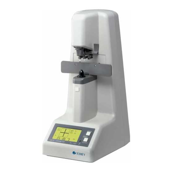
OPERATOR MANUAL
AUTO LENSMETER
TL-100
• Read this Operator Manual carefully before using this instrument in order to operate it
properly and safely.
• Do not use procedures other than those specified in this manual.
• Keep this Operator Manual handy when operating this instrument.
• For any questions about this instrument or about this manual, contact your local TOMEY
representative.
HOLD
Advertisement
Table of Contents

Subscribe to Our Youtube Channel
Related Manuals for Tomey TL-100


Summary of Contents for Tomey TL-100
- Page 1 • Do not use procedures other than those specified in this manual. • Keep this Operator Manual handy when operating this instrument. • For any questions about this instrument or about this manual, contact your local TOMEY representative.
- Page 2 SYMBOLS USED IN THIS MANUAL The symbols used in this manual represent the following messages: • This is a precaution that, if unheeded, will result in a hazard- ous situation where there is an imminent danger of serious injury or death. •...
-
Page 3: Table Of Contents
CONTENTS 1. PRIOR TO USE ............1-1 1.1 Cautionary notes ..............1-1 1.2 Unpacking ................1-3 1.3 Explanation of terms ............1-4 1.4 Outline of operation ............1-5 2. COMPONENT LIST AND FUNCTIONS ....2-1 2.1 Front ...................2-1 2.2 Back ...................2-2 2.3 Screen layout ..............2-3 3. - Page 4 Storage ................4-6 Packing materials ............. 4-6 5. TROUBLESHOOTING ..........5-1 5.1 Troubleshooting guide ............5-1 5.1.1 General operation .............. 5-1 5.1.2 Progressive addition lens measurement ......5-3 5.2 Error messages ..............5-7 6. SPARE PARTS ............6-1 7. SPECIFICATIONS ........... 7-1 7.1 Measurement ..............7-1 7.2 Data control ................7-1 7.3 Physical dimensions and electrical requirements ....
- Page 5 ( This page is left intentionally blank )
-
Page 6: Prior To Use
1. PRIOR TO USE • Read this Operator Manual carefully before using this instrument in order to operate it properly and safely. • Do not use procedures other than those specified in this manual. CAUTIONARY NOTES • Never install this instrument near locations where explosive or flammable materials are used or stored. - Page 7 - If this instrument has been idle for a long period of time, confirm that it is functioning properly and safely before using it again. For this, TOMEY recommends using a trial lens set for checking accuracy. • Due to vibration during transport and/or environmental changes of storage, the ink may leak out of the marking device cartridge.
-
Page 8: Unpacking
Upon unpacking, inspect that all the components are present and that there is no visible damage to any of them. If there are any missing or damaged items, immediately contact your Tomey representative or local distributor. • Be sure to retain all shipping and packing materials for reuse if the instrument will be transported or shipped. -
Page 9: Explanation Of Terms
EXPLANATION OF TERMS • D ..........Diopter (a unit of measurement referring to the refractive power of a lens; reciprocal of the focal length of the lens in meters) • ∆ ..........Prism diopter (a unit of the measurement of angular deviation of light produced by a lens) •... -
Page 10: Outline Of Operation
The AUTO LENSMETER TL-100 is an instrument for the automatic measurement of refractive and prism power of spectacles and contact lenses. The TL-100 is composed of a built-in optical system, an electronic processing system, and a mechanical system. Placing spectacles or contact lenses on the nose piece initiates automatic measurement. - Page 11 ( This page is left intentionally blank )
-
Page 12: Component List And Functions
2. COMPONENT LIST AND FUNCTIONS FRONT Clamp Stabilizes the lens when marking it. Marking device Marks the center and axis orientation of the lens. Nose piece Lens is placed on the nose piece. Lens table Used to standardize the orientation of spec- tacles for accurate cylinder axis measurement and vertical prism measurement. -
Page 13: Back
BACK AUTO LENSMETER TL-100 100-240V~ 50/60Hz 35VA MANUFACTURER NAME: TOMEY CORPORATION ADDRESS: 2-11-33 Noritakeshinmachi, Nishi-ku, Nagoya 451-0051 Japan Name plate Shows the serial number. AC power terminal The accompanying power cord is connected to this terminal. T2A 250V Fuse holder The fuse is mounted in this holder. -
Page 14: Screen Layout
SCREEN LAYOUT Holding data [HOLD]: Indicates the data are Indication of the automatic being held. measurement mode Alignment screen [AUTO]: Automatic measure- Used for centering the lens ment mode Lens modes Single vision lens mode: Multi-focal lens mode: Contact lens mode: Measuremet Condition AUTO MODE... - Page 15 ( This page is left intentionally blank )
-
Page 16: Method Of Operation
Nose piece H O L 1) Connect the female end of the power cord into the power terminal on the back of the TL-100 and the male end into a 3-prong power outlet. 2) Turn the power switch ON. 3) The initial screen will appear for approximately five seconds. - Page 17 4) The measurement screen will appear. AUTO MODE STEP AXIS • Do not place a lens onto the nose piece until after the measurement screen appears. • Turning the instrument on with the lens already on the nose piece initiates a beep and indicates "INITIAL ERROR" on the LCD.
-
Page 18: Measuring Methods
MEASURING METHODS 3.2.1 MEASURING SINGLE VISION LENSES If the instrument is not in Single Vision mode ( ), change to Single Vision mode by pressing the MODE button. Single Vision mode ( ), Multi-focal mode ( ) and Contact Lens mode ( are set consecutively each time the MODE button is pressed. - Page 19 • The right lens must be measured first and then the left lens. 3) Move the lens gently right and left, back and forth to center the cursor (+) on the crosshair. The reading will be displayed in real time. 4) When alignment is achieved, a beep will sound and the reading will be automatically held.
-
Page 20: B) Manual Hold Mode
b) Manual Hold Mode • Thrusting the lens onto the nose piece or moving the lens quickly may result in damage to the lens. 1) If the instrument is in automatic (AUTO) hold mode and you wish to change to manual hold mode, press the HOLD button (located below the nose piece) for approximately 1 second, until "AUTO"... - Page 21 4) When alignment is achieved, press the HOLD button. The reading will be held, and "HOLD" will be displayed at the top left of the screen. AUTO MODE HOLD STEP AXIS 5) When the right lens is removed from the nose piece, the instrument is ready to measure the left lens.
-
Page 22: Measuring Multi-Focal Lenses (Prog Mode)
3.2.2 MEASURING MULTI-FOCAL LENSES (MULTI-FOCAL MODE) The MULTI-FOCAL mode is used for measuring both progressive addition lenses and bi-focal lenses. • Refer to the Section 5.1 "Troubleshooting guide" for details of measuring in the MULTI-FOCAL mode. • In AUTO mode, the add reading is automatically held. Press the HOLD button for approximately 1 second without placing a lens on the nose piece to switch the mode between AUTO and MANUAL. - Page 23 • The right lens must be measured first and then the left lens. b. Move the lens gently right and left, back and forth to align the cursor (+) on the crosshair. AUTO MODE STEP AXIS c. When the center of the near portion is found, a beep will sound, following which the measurement display will change for the masurement of the distance portion of the lens.
- Page 24 3) Measure the Distance Zone a. Move the lens away from you to place the distance zone over the nose piece. Move the lens gently right and left, back and forth to align the cursor (+) on the crosshair. AUTO MODE STEP AXIS...
- Page 25 4) Measuring at the Near Zone a. ADD will be indicated on the screen. b. Move the frame toward you, and move it right and left so that the cross cursor (+) always stays in the progressive channel. AUTO MODE STEP AXIS c.
- Page 26 e. In AUTO mode, a beep will sound, and the ADD reading will be held automatically. In Manual mode, press the HOLD button. If the near zone of a progressive addition lens is located very close to the frame, the cross cursor (+) may not change to " "...
-
Page 27: B) Measuring Bifocal Lenses
b) Measuring Bifocal Lenses • Thrusting a lens onto the nose piece or moving a lens quickly may result in damage to the lens. • In AUTO mode, the ADD reading is automatically held . Press the HOLD button for approximately 1 second without placing a lens on the nose piece to switch the mode between AUTO and MANUAL. - Page 28 4) Measure the Distance Zone a. Move the lens gently right and left, back and forth to align the cursor ("+" mark) on the crosshair. b. If AUTO HOLD is ON, when the cursor is aligned, a beep will sound, and the reading of the distance zone will be held automatically.
- Page 29 AUTO MODE HOLD STEP AXIS 6) When the left lens is removed from the nose piece, the instrument is ready to measure the left lens. 7) Place the left lens on the nose piece as described in step 2 and follow steps 3-5.
-
Page 30: Measuring Prism
3.2.3 MEASURING PRISM To measure prism, select one of the prism measurement options descibed below (See Section 3.4, Setup). The prism readings are displayed on each side of the display. AUTO MODE STEP PRISM PRISM AXIS There are two prism modes: Rectangular Coordinates Prism magnitude is expressed in prism diopters. -
Page 31: Measuring High Index Lenses (Hi Mode)
3.2.4 MEASURING HIGH INDEX LENSES (HI MODE) • It is reccomended to use the High Index (HI) mode when measuring high index lenses. 1) The default Abbe value for normal index lenses is 60. When the instrument is set in HI mode, the default Abbe number is 35. The Abbe number used for HI mode may be changed, as described in Section 3.4, Setup. -
Page 32: Measuring Contact Lenses (Cl Mode)
3.2.5 MEASURING CONTACT LENSES (CL MODE) • Be sure to use Contact Lens mode (CL mode) when measuring contact lenses. Measuring in Spectacle mode may result in errors because the measurement conditions for contact lenses are different from those for spectacles. 1) Remove the standard nose piece and install the Contact Lens nose piece. - Page 33 Hard Contact Lenses 1) Place the contact lens on the nose piece with the front (convex) surface upward. 2) Move the lens back/forth and left/right for centering. Refer to Section 3.2.1, Measuring single vision lenses, for measurement procedures. b) Soft Contact Lenses •...
-
Page 34: Recalling The Readings (Reading)
3.2.6 RECALLING THE READINGS (READING) One right lens measurement and one left lens measurement are temporarily stored in the memory. These readings can be recalled and displayed by pressing the READING button. 1) After measuring the lens, press the READING button. 2) The reading obtained for the right lens will be displayed first. -
Page 35: Detecting Progressive Lenses
• If no readings have been stored, nothing will be displayed when the READING button is pressed. • To return to the measurement display, remove the lens from the nose piece and either place a lens on the nose piece again or press any button, except the READING button. -
Page 36: Operating The Clamp, Marking Device And Lens Table
OPERATING THE CLAMP, MARKING DEVICE AND LENS TABLE 3.3.1 CLAMP • Lower the clamp slowly. Quick lowering of the clamp may result in damage to the lens. The clamp is used to stabilize the position of the lens when marking it. (Refer to Section 3.3.2 "Marking device.") 1) Raise the clamp upward with your finger to release the lock. -
Page 37: Marking Device
3.3.2 MARKING DEVICE The marking device places three marks on the lens, one in the center of the lens and one approximately 16 mm lateral to the center on each side along the lens axis. 1) Press and turn the marking lever, causing the pens to descend and mark the lens surface. -
Page 38: Lens Table
3.3.3 LENS TABLE The lens table serves to standardize the axis of cylindrical lenses and the height of the frame for measuring vertical prism. 1) Adjust the lens table so that it meets bottom edge of the frame by pushing or pulling it. 2) The outer diameter of the lens is indicated on the scale on the upper surface of the nose section. -
Page 39: Setup
SETUP Indication units and measurement conditions may be selected and modified in the MENU MODE. The highlighted menu indicates that it has been selected. 1) Simultaneously press the MODE button and the READING button to enter the MENU MODE. The screen will change to SETUP and "CYL" will flash on and off at the upper right corner of the screen. - Page 40 d. ABBE NUMBER The Abbe number in the normal mode is 60 (fixed value). The Abbe number in the HI mode may be changed in increments of 5 ranging from 30 to 60 (Default setting: 35). AUTO MODE STEP PRISM PRISM AXIS AXIS e.
- Page 41 AUTO MODE STEP PRISM PRISM AXIS AXIS f. AUTO PROG Automatic activation of the MULTI-FOCAL mode when a progressive addition is detected. OFF: MULTI-FOCAL mode is not automatically activated when a progressive addition is detected. AUTO MODE STEP PRISM AXIS PRISM AXIS 5) Press the HOLD button when setup is complete.
- Page 42 • All settings are saved in non-volatile memory and will not be lost when the power is turned off. It is not necessary to set them every time the unit is turned on. • To change the settings, repeat the above procedures. •...
-
Page 43: Lcd Contrast Adjustment
LCD CONTRAST ADJUSTMENT The contrast of the LCD (Liquid Crystal Display) can be modified by turning the contrast adjuster on the front panel with a Phillips screwdriver. HOL D 3-28 3.5 LCD CONTRAST ADJUSTMENT... -
Page 44: Automatic Power Saving Function (Auto Power Off)
AUTOMATIC POWER SAVING FUNCTION (AUTO POWER OFF) 1) When the instrument is not in use for more than 10 minutes (i.e., when no lens has been placed in the nose piece and no buttons have been pressed), the built-in motor and the internal light source will go off automatically. - Page 45 ( This page is left intentionally blank ) 3-30...
-
Page 46: Maintenance And Inspection
Tomey, nor to a product whose serial number or batch number is removed, altered or effaced. THIS WARRANTY IS EXPRESSLY IN LIEU OF ANY AND ALL... -
Page 47: Routine Maintenance
ROUTINE MAINTENANCE • Do not touch the optical elements, such as the cover glass, with your fingers. Keep them clean. Accuracy of the reading may be adversely affected by dust or dirt. • Keep the dust cover over the instrument when the instrument is not in immediate use. - Page 48 It may be necessary to relace the fuse if the instrument panel does not light up when the power in turned on. • Disconnect the power cord immediately if problems persist after replacing the fuses. Contact your Tomey representative or local distributor. 1) Turn off the power.
-
Page 49: Replacing Spare Parts
4.3.2 INK CARTRIDGE Replace the ink cartridge with a new one when ink is low. Replacement cartridges can be obtained from your Tomey representative or local distributor. • Be sure to use genuine ink cartridges (as specified in this manual). - Page 50 • Fastening the screw too tightly may result in damage to the ink cartridge. Use the accompanying screws and springs only. If the screws and/or the springs are lost , contact your Tomey representative or local distributor. 4.3 REPLACING SPARE PARTS...
-
Page 51: Storage
STORAGE • Do not store this instrument in a location where it might be exposed to water. • Avoid excessive atmospheric pressure, high temperature, excessive humidity, poor ventilation, direct sunlight, dust, salt or sulfur in the air. • Ascertain that factors such as excessive slope, vibration and impact will not endanger the instrument (including during transportation). -
Page 52: Troubleshooting
• Do not attempt measures other than those described below. • If the problems persist after checking the following, stop using the unit and immediately contact your Tomey representative for inspection or repair. TROUBLESHOOTING GUIDE 5.1.1 GENERAL OPERATION The LCD does not Light Up After Turning ON. - Page 53 Cause 3: The cover glass under the nose piece is not clean. Action: Turn off the power. Remove the nose piece and then clean the cover glass (See Section 4.2.1, Cleaning cover glass). Replace the nose piece and turn the power on again.
-
Page 54: Progressive Addition Lens Measurement
5.1.2 Progressive Addition Lens Measurement The Cursor Cannot be Centered in the Progressive Channel. Cause 1: With progressive lenses which have a small power difference between the far point area and the near point area, aligning the cursor to the center may not be achievable. Action : The beginning of the progressive channel is located in approximately the center of the lens or the center of the frame. - Page 55 Cause 3: The near point area in a small frame lens may be positioned very near to the edge of the frame or even outside of the frame. It may not be possible to detect the near point area in such lenses. Action: Press HOLD button when judging the highest addition value when the cursor is in the progressive zone.
- Page 56 Cause 2 : TL-100 senses refractive power change along the progressive extent. If the power change is close to 0 diopter, the TL-100 treats it as a near point. Example: When a lens with a SPH reading of -1.00 diopters and an add reading of 2.00 diopters is measured, there is a point where the...
- Page 57 The ADD Readings are Higher than the Nominal Value. Cause: Some progressive lenses may have a peak of ADD below the near power circle. With these lenses, the ADD readings may be higher than the nominal values. Distance power circle ADD (measurement) >...
-
Page 58: Error Messages
2) ERROR MT Cause: Malfunction of the DC Motor. MODE STEP ERROR AXIS Action: Contact your Tomey representative or local distributor. 3) ERROR OV Cause: Over/Under Flow MODE STEP ERROR AXIS Action: The power of the lens is out of the measuring range. - Page 59 4) ERROR INIT ERR ERROR Action: Remove the lens from the nose piece, and press any button. Make sure the nose piece is seated properly and press any button. Clean the cover glass located under the nose piece and press any button.
-
Page 60: Spare Parts
6. SPARE PARTS The following spare parts can be purchased from your Tomey representative or local distributor. • Spare fuse (250V, 2.0A) • Ink cartridges • Dust cover 6. SPARE PARTS... - Page 61 ( This page is left intentionally blank )
-
Page 62: Specifications
7. SPECIFICATIONS MEASUREMENT • Range ± 25D Spherical power (S reading): ±9.99D Cylindrical power (C reading): Axis of cylindrical power (A reading): 0 to 180 degrees Addition reading (ADD reading): 0 to 9.99 D 0 to 9.99 ∆ Prism power (P reading): •... -
Page 63: Environmental Conditions
ENVIRONMENTAL CONDITIONS • Installation site: indoors +10°C to + 40°C (+50 °F to +104°F) • Operating temperature range: maximum relative humidity 80% for temperatures up to 31°C decreasing linearly to 50% relative humidity at 40°C ±10% of the normal voltage •... -
Page 64: Index
8. INDEX Abbe number 1-4, 3-16, 3-25 Far point area 3-9, 3-13, 5-3, 5-4 AC power terminal 2-2 Fuse 4-3, 5-1, 6-1 ADD 1-4, 3-10, 3-13, 5-4, 5-5 Fuse holder 2-2, 4-3 Alignment screen 2-3 Approved international standards 7-2 Hard contact lenses 3-18 AUTO POWER OFF 3-31 HI 1-4, 3-16 Automatic hold mode 3-3, 3-7, 3-12, 3-25... - Page 65 Packing materials 4-6 Power cord 3-1, 5-1 Power saving function 3-29 Power switch 2-2, 3-1 Progressive addition lenses 3-7 Polar coordinates 3-15, 3-25 Prism 3-15, 3-25 PSM 1-4, 3-25 READING button 2-1, 3-4, 3-6, 3-11, 3-14, 3-19, 3-20 READING 3-19, 3-24, 3-25 Recalling the readings 3-19 Rectangular coordinates 3-15, 3-25 Replacing spare parts 4-3...
- Page 66 Tomey Corporation (Tomey Japan) 2-11-33 Noritakeshinmachi Nishi-ku, Nagoya 451-0051 JAPAN Tel: +81 52-581-5327 Fax: +81 52-561-4735 North/South America Tomey Corporation USA (Tomey USA) 300 Second Ave. Waltham, MA 02451 USA Tel: +1 781-890-1515 Fax: +1 781-290-5885 Europe Tomey GmbH (Tomey Europe)
- Page 67 ID: 0208...
Need help?
Do you have a question about the TL-100 and is the answer not in the manual?
Questions and answers